

Mounts by
A division of David Engineering & Mfg. Inc.
Model
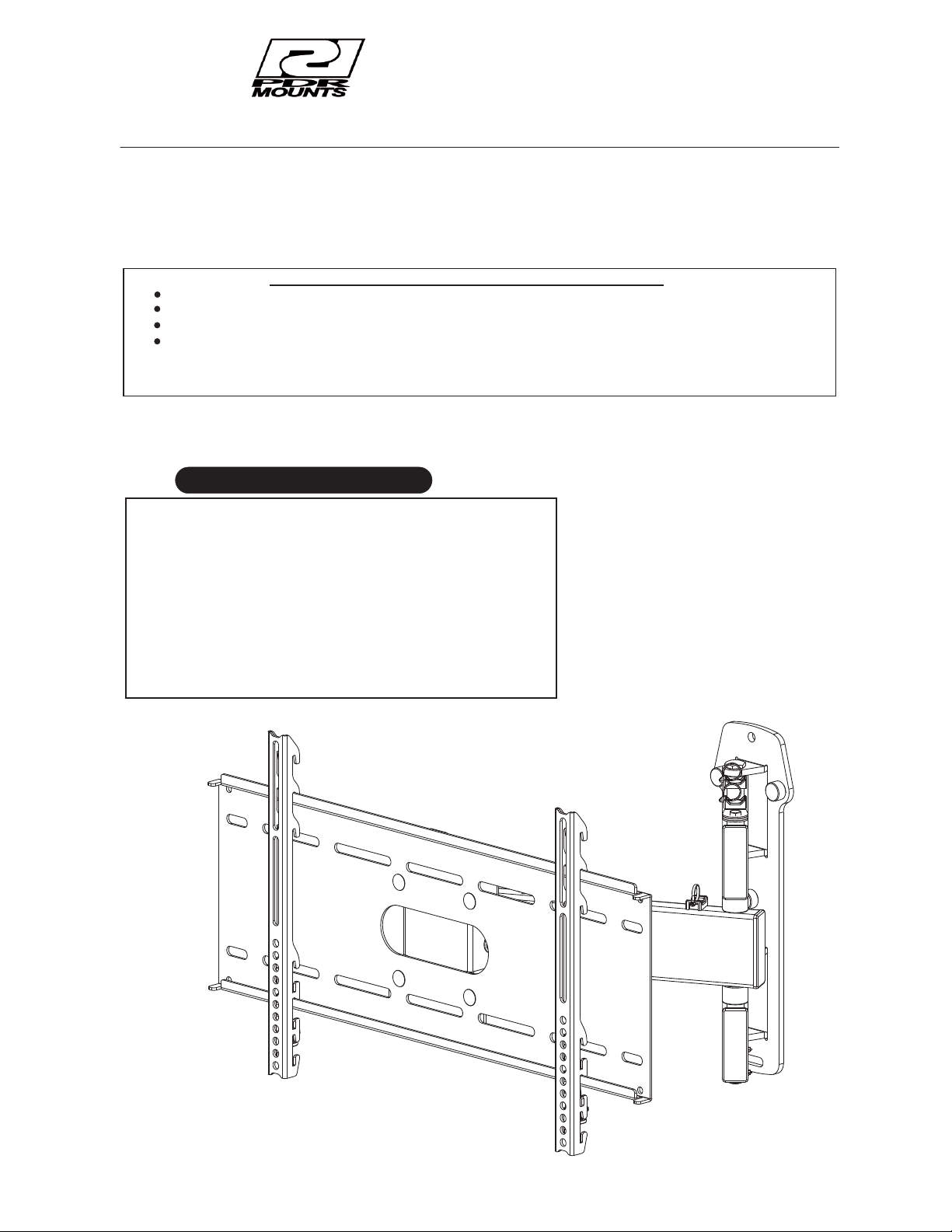
AWM125-120 ARTICULATING WALL MOUNT INSTRUCTIONS
Thank you for purchasing the PDR mount.
To ensure the correct usage, please read and follow the instructions
All PDR mounts and adapters carry a limited lifetime warranty against defects in material and workmanship. We are not liable
for improper installation that results in damage to mounts, adapters or presentation equipment.
To register visit our web site @ www.pdrmounts.com
Do not attempt to perform this work by yourself.
Request an installation specialist to install this unit.
Manufacturer assumes absolutely no responsibility for injuries and damages that may occur due to improper installation and handling.
Please remember that if you remove the panel display from the wall later, you will find the screw holes and anchor bolts for t
mounting unit left on the wall. Also note that long use of the panel display may discolor the wall around it due to its heat a
airflow.
Special techniques are necessary for installation of the panel display mount.
manual thoroughly. Please store the instructions in a safe place
for future reference.
nd
he
To ensure customer safety, be sure to decide the installation location so that the strength is sufficient to withstand the weight
display and the wall mount.
Always use at least two persons for all installations.
Fully tighten all of the mounting screws as specified in the installation instructions.
Simple to adjust
R
Adapter plate included
R
125 lb rated
R
AWM 125-120 FITS 22” TO 36” DISPLAYS
R
Rugged heavy gauge metal construction
R
Tough powder-coated finish
R
Extends 20.7” from the wall and closes to under 4.6”
R
Pivots left or right, tilts up 5 deg. and down 15 deg.
R
3 adjustable height positions
R
Includes cable management system
R
Tension bolts to adjust smooth action and eliminate creep
R
Features
Fig 1
of both the panel
1
INSTALLATION LOCATION
WARNING
The wall where the wall mount is to
the panel display and wall mount. Measures should al
withstand the force of earthquakes,
Note: Incorrect installation can cause the
be installed must be capable of long-term support of the total load of
vibration and other external forces.
panel display to fall and cause injury.
Total load ( panel display + mount )
MAXIMUM WEIGHT= 125 Lbs. ( 57 Kg.)
INSTALLATION ON A WOODEN WALL
Always install so that the load is supported by a wood stud. If
Do not install on decorative posts or plaster board.
the strength of the wood studs is not sufficient, add reinforcement.
Always confirm the center of the stud is used for the installation.
CAUTION
Avoid installing in locations where the temperature and humidity are excessively high, and where contact with any
water is possible. These can result in fire or electric shock.
Do not install close to an air conditioner intake or outlet. Do
oily smoke or tobacco smoke. Fire could result.
Do not block the ventilation holes. Leave sufficient clearance in regard to the surroundings to avoid blocking the ventilation..
The internal temperature could elevate and possibly result in fire. Install the panel (4") or more away from surroundings.
Install only on a vertical surface. Avoid
elevate and possibly result in fire. Injury or damage could also result from falling.
Do not install in locations where there is excessive vibration or impact. Injury and damage could result from the panel display
falling.
Do not install where there is direct sunlight or other strong
.
sloped surfaces. Also, do not install facing upward. The internal temperature could
so be taken to ensure sufficient strength to
not install in locations where there are excessive amounts of dust,
light. Strong light could result in eye fatigue during usage.
WARNING
Use the specified bolts and screws in the specified places and tighten firmly. Failure to do this could cause injury if the pan
display falls.
Do not alter any of the parts. Do not use broken parts. This
Always use at least two people to perform the installation work. Injury could result from dropping heavy objects.
could result with injury due to the panel display falling.
C a u t i o n : I n s t a l l a t i o n o f u n i t i s t o b e c a r r i e d o u t b y q u a l i f i e d t e c h n i c i a n s o n l y . I n s t a l l i n a n a p p r o p r i a t e
l o c a t i o n b y c h e c k i n g t h e w a l l s t r u c t u r e a n d d u r a b i l i t y f o r s a f e t y a n d a c c i d e n t p r e v e n t i o n .
Rev 100708
2
el

SUPPLIED HARDWARE
1
4
PHILLIPS MACHINE SCREW
7
PH-M-08-40-00
M8 X 40 PAN HEAD
PHILLIPS MACHINE SCREW
PHILLIPS MACHINE SCREW
4 REQUIRED
PH-M-06-40-00
M6 X 40 PAN HEAD
4 REQUIRED
PH-M-05-40-00
M5 X 40 PAN HEAD
4 REQUIRED
PH-M-08-16-00
2
M8 X 16 PAN HEAD
PHILLIPS MACHINE SCREW
4 REQUIRED
PH-M-06-16-00
5
M6 X 16 PAN HEAD
PHILLIPS MACHINE SCREW
8
PHILLIPS MACHINE SCREW
4 REQUIRED
PH-M-05-16-00
M5 X 16 PAN HEAD
4 REQUIRED
3
6
PHILLIPS MACHINE SCREW
9
SP-E-32-10-01
.32 ID X .75 OD X 1.00 LONG
PLASTIC SPACER
4 REQUIRED
PH-M-04-16-00
M4 X 16 PAN HEAD
4 REQUIRED
FW-M-04-09-00
M4 STEEL FLAT WASHER
4 REQUIRED
10
12
PH-E-25-15-00
1/4-20 X 1 1/2 PAN HEAD
PHILIPS MACHINE SCREW
2 REQUIRED
FW-E-31-06-00
5/16 X 7/8 USS STEEL
FLAT WASHER
3 REQUIRED
15
PDM-0044
11
13
16
LB-E-31-25-00
5/16 X 2 1/2 LAG BOLT
3 REQUIRED
PDM-0071
LOCKING PLATE
2 REQUIRED
PART NUMBER
CT-E-37-37-00
ZT-E-00-50-00
14
NYLON ZIP TIE
4 REQUIRED
PART NUMBER
17
PH-E-25-50-ST
LINEAR (RECTANGULAR)
MULTI WASHER
4 REQUIRED
1/4-20 X ½" SELF T APPING
PAN HEAD SCREW
4 REQUIRED
PLASTIC CABLE MANAGEMENT
CABLE T IE HOLDER
4 REQUIRED
3

Model AWM125-120
DRAWING SPECIFICATIONS
Single stud articulating wall mount
20.7
15 DEG
5 DEG
14.00
4.00
24.00
C
L
8.05
3.07
4°
4.67
5.39
4

1. FASTEN MOUNT TO THE WALL
Determine the exact mounting location of the wall mount prior to the installation, considering the swing of the articulating arm.
The AWM125-120 mount must be secured to the CENTER of the wall stud capable of at least (4) times the weight of the display and mount.
The height of the AWM125-120 should be mounted at the same horizontal center line as the desired display center line (viewing center line).
1:Position the AWM125-120 mount to the desired position. Mark and Pre drill the top and bottom holes with a 3/16” (5mm) hole . SEE FIG 2
2: Insert the lag bolt and washer (item 11 and 12) into the top hole and secure to the AWM125-120 mount.
3: Next insert the second lag bolt and washer into the slotted bottom hole. Position with a level tighten the bottom bolt.
4:Fully extend the arm and swing the mount from left to right . Check that the mount is level in both positions. If necessary loosen the bottom bolt and set to a level
position and re tighten the bolt.
5:Pre drill and Install the center lag bolt and tighten. SEE Fig 2
(item 11 and 12)
Fig 2
AWM125-120
DISPLAY CENTER LINE
WOOD STUDS
(std construction 2 x 4
studs and 1/2” wallboard)
lag bolts
VIEWING
HORIZONTAL
CENTER LINE
Adjustment for level
C
L
4°
FLOOR LINE
2. ATTACH THE DISPLAY BRACKET TO THE DISPLAY
1: Lay the display face down on a padded surface.
2: Using the hardware supplied ( see page 3) attach the display bracket to the display. SEE FIG 3
3: Check the depth of the mounting holes to assure you are using the proper length screws supplied .
4: Make note to attach the top of the display bracket to the top of the display.
5: Spacers supplied (1,3,4,7), may be necessary for use, to avoid obstructions on the back surface of the display.
6: Make sure to tighten all fasteners before mounting on the AWM125-120 arm. Care should be taken to not over tighten bolts into the display.
and longer screws
NOTE: Do not over tighten the bracket mounting screws as damage to the display internal mounting threads could occur.
Fig 3
SEE FIG 3
Mounting hardware 1,2,3,4,5,6,7,8,9
Linear multi washer (15)
Display bracket
Optional plastic spacers ( 3 )
Panel display bottom edge
5

1: With the display brackets attached to the display, lift and place the brackets on to the in either the top middle or bottom slots. SEE FIG 4
2: Center the display from left to right on the mounting plate.
3: Screw the 1/4-20 screw (10) into the locking plate (13)
4: Place the locking tab assembly into the slots on the display bracket, and tighten the 1/4-20 screw (10) on each locking tab assembly. SEE FIG 5
3. Mounting the display onto the AWM125-120 Articulating arm
mounting plate
Fig 4
DISPLAY BRACKETS
Fig 5
TRI KNOB
MOUNTING PLATE
large view
LOCKING TAB ASSEMBLY 1/4-20 screw
Adjust by tightening the tension bolts to suit the desired freedom of movement See fig 6
1: Lift the tie holder(16) on the lock tab to allow access the bolt to adjust the tension on the arm center. Replace the tie holder (16) after adjustment.
3: Two other tension bolts can be tightened or loosened to suit. SEE FIG 6
2: Adjust the tilt by loosening the Tri knob on the side of the AWM125-120 and adjust back or forward for best viewing angle. See fig 6
3: Place the plastic tie holders (16) in the desired holes, and using zip ties (14) attach the cables.
4: Make sure you articulate the mount from side to side looking for any pinching of the cables.
Fig 6
3. Final adjustment and cable management
NYLON ZIP TIE
TENSION BOLTS
CABLE
SCREW LOCK TAB
TENSION ADJUSTMENT BOLT
6
 Loading...