

PDQ Yachts 36 Capella Owner's Manual
PDQ 36 Capella
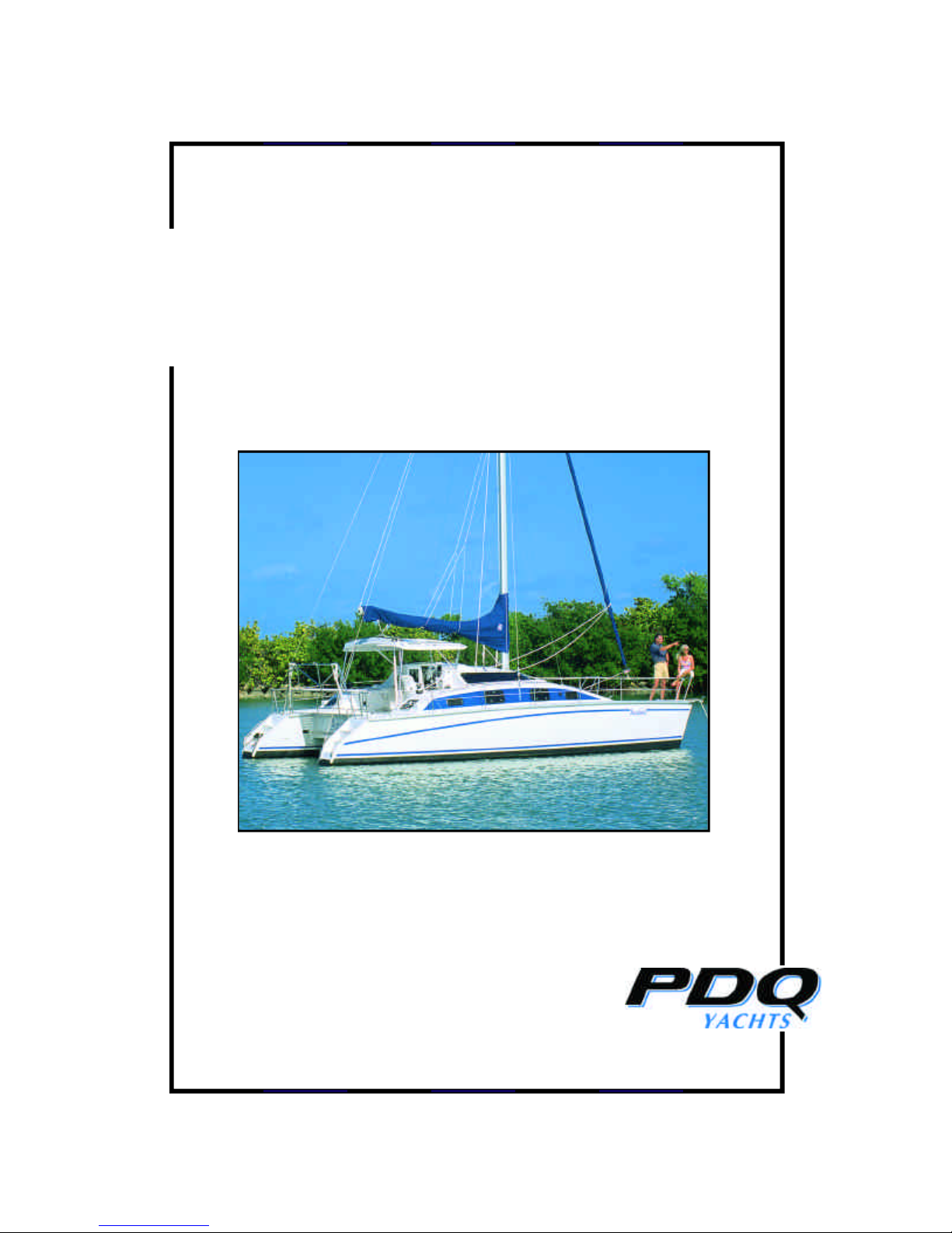
PDQ 36 Capella
Owner’s Manual

OWNER’S MANUAL CONTENTS
INTRODUCTION ii
GENERAL ............................................. 1
General Description 1-1
Your Warranty 1-2
Weights and Measures 1-3
SAFETY ................................................. 2
Locations of Safety Equipment 2-1
Your Responsibilities 2-2
Statutory Requirements 2-3
Navigation Lights 2-4
Safety Equipment 2-5
PROPULSION AND STEERING ....... 3
Auxiliary Engines 3-1
Fuel Systems 3-2
Steering 3-3
Rigging and Sails 3-4
SHIP’S SYSTEMS................................. 4
AC Electrical System 4-1
DC Electrical System 4-2
Bilge Pumps 4-3
Propane System 4-4
Galley Stove 4-5
Fresh Water System 4-6
Water Heater 4-7
Refrigeration 4-8
Head 4-9
Holding Tank 4-10
Seacocks 4-11
OPTIONAL & SPECIAL
EQUIPMENT ............................ 5
Anchor Options 5-1
Sail Options 5-2
Galley Options 5-3
Electronics 5-4
Inverter/Charger 5-5
Generator 5-6
Air Conditioning 5-7
OPERATION .........................................6
Preparing for Departure - Checklist 6-1
Returning to Harbour – Checklist 6-2
Cruising - Sail 6-3
- Power 6-4
Anchoring 6-5
Docking 6-6
Handling, Storage & Transport
On Shore 6-7
MAINTENANCE & REPAIR ..............7
The Importance of Preventative
Maintenance 7-1
Suggested Schedules 7-2
Rigging & Sails 7-3
Engines 7-4
Steering 7-5
Service Systems 7-6
Hull & Deck 7-7
Interior 7-8
Winterize 7-9
Recommended Spare Parts 7-10
Recommended Tools 7-11
Troubleshooting 7-12
APPENDIX
List of Major Equipment A-1
Data & Contacts
Maint. & Repair Record A-2
Drawings & Data Sheets A-3
PDQ 36 Capella - Owner’s Manual

Introduction ii
This manual is the product of building more than 170 PDQs. It reflects our experience
of working with the boats and their owners, and includes a great variety of ideas,
improvements and, inevitably, solutions that we have shared. We hope that as you
settle in to your new PDQ Capella, you will share your ideas and experiences with us
so they may serve to benefit others as the experiences of others have benefited you.
We update this manual to reflect our policy of continual improvement. We are
confident that it covers your vessel accurately when used in conjunction with the
equipment manuals supplied. With the many possibilities of options and layouts,
however, we have never built two boats that are exactly alike, so there may be points of
difference in equipment and options. The equipment manufacturers also continually
change their products.
PDQ Yachts Inc.
202 South Blair St. 1-6
Whitby, ON. Canada
L1N 8X9
Toll free: (888) 297-2287
Tel: (905) 430-2582
Fax: (905) 430-8306
E-Mail: info@pdqyachts,com
Web Site: www.pdqyachts.com
Disclaimer
Although PDQ Yachts Inc. has prepared this manual carefully, the company makes no
warranty or representation, either express or implied, with respect to the accuracy of
the contents of this manual. In no event will the company be liable for direct, indirect,
special or consequential damages resulting from any defects or inaccuracy in this
manual. No employee or agent of the company is authorized to make any modifications
or additions to this policy.
PDQ 36 Capella - Owner’s Manual

GENERAL 1
General Description 1-1
Your 36 Capella cruising catamaran combines comfortable accommodation, good
performance and pleasing appearance. It is intended primarily for coastal cruising and
island hopping, and is capable of offshore passages.
This is a strong, safe boat, built by experienced boat builders with best-quality
materials, to the design of a professional engineer who is an experienced multihull
cruiser. There are six watertight compartments: 4 forward and 2 aft. The fin keels
have a sacrificial section to allow the boat to stand up to grounding at relative high
speed.
The layout of the boat gives two double berths forward. A large open-p lan saloon
places the galley on the port side and navigation station on the starboard side. The
large head is located in the starboard aft cabin. The port aft cabin is normally custom
fit to individual requirements.
The “Classic” version is the original concept, providing lightweight, economical and
reliable auxiliary power with two Yamaha outboard motors, specially designed for this
purpose. The “LRC” or Long Range Cruiser version is equipped with Yanmar Diesel
Sail drive inboard engines, for the dedicated sailors who want the additional power and
security of twin Diesel engines and skeg protected rudders.
Your Warranty 1-2
The terms of your Warranty are included in your purchase contract,
which should be referred to for details.
PDQ 36 Capella - Owner’s Manual

Weights and Measures 1-3
Measurements
Basic Dimensions Standard Metric
LOA
LWL
BOA
36' 5" 11.1 m
34' 4" 10.5 m
18' 3" 5.6 m
Beam (hull centres) 13' 0" 4.0 m
Beam (waterline) 3' 0" 0.9 m *
Draft - Classic 2' 10" 0.9 m *
- LRC 2' 11" 0.9 m *
Weight - Classic 10,000 lbs Kg *
- LRC 10,700 lbs Kg *
Height with mast
above water
47' 0" 14.3 m
* Note: Weight and draft are dependent on equipment, fluids and stores on board
Sail Area
Main 640 sq. ft 25.5 m²
Jib 224 sq. ft 30.2 m²
Genoa 455 sq. ft 17.6 m²
Capacities
Diesel fuel 55 US gal. 208 l.
Fresh water 85 Us gal. 321 l.
Holding Tank
Electrical
AC – 115 volts. 60 cycle, 30-amps.
DC – 12 volts. 450 amp hour service batteries: Classic- one start battery,
PDQ 36 Capella - Owner’s Manual
35 US gal. 132 l.
LRC- two start batteries.

SAFETY 2
Location of Safety Equipment 2-1
Please complete this section as a quick reference for others on board this vessel.
Canadian and US Coast Guard requirements are listed in section 2-5.
• Distress signals and fire extinguisher charges expire and must be replaced or
recharged,
• A strong bucket does double duty as a fire extinguisher and emergency bilge
pump.
• Life jackets should be kept clean and dry; try them periodically.
• From time to time, try your skill at throwing your life ring or other
throwable device to someone in the water.
• Develop simple instructions for reacting to emergencies such as fire, man-
overboard, etc.
Fire Extinguishers:
Life Jackets:
Throw able Devices:
Visual Distress Signals:
Sound Signaling Devices:
Seacock Locations:
Propane Shut-Off Valve:
PDQ 36 Capella - Owner’s Manual

Your Responsibilities 2-2
The yachts we build are a product of our experience, and the thoughts and suggestions
offered by people who have chosen and used our yachts. We believe that they are
among the best multihulls built in the world. Our policy of continual improvement
ensures that each is better than the last.
Caution: Marine law requires that the owner must keep his vessel in a
seaworthy condition, properly equipped and properly
manned, and must only allow his vessel to be operated by
competent persons with the ordinary requisite skill.
In the end, therefore, enjoyment of your PDQ power yacht and your success in its
operation depends on the care and quality of effort you devote to knowledge of vessel
operation and the care of the yacht itself.
Knowledge
Instruction in the safe operation of a large vessel cannot be taught in the confines of this
manual. Parts can be taught in classrooms, but the conscientious sailor must actively
seek much knowledge on the water. Courses in navigation and seamanship are taught
by:
Canadian Power and Sail Squadrons US Power Squadrons
26 Golden gate Court (800) 336-2628
Scarborough, ON. Canada in VA., (800) 245-2628
M1P 3A5
(416) 293-2438
Advertisements with local contact addresses are frequently posted in yacht clubs,
marine supply stores and marina bulletin boards. Boat owners in your area may ha ve
other suggestions.
These courses lay a firm foundation of knowledge in:
• Seamanship and boat handling, basic to advanced
• Regulations for prevention of collision, international and inland
• Navigation – basic to advanced
• Radio communication
• Safety at sea
• First aid
• Dealing with serious storms
• Distress communication
• Weather prediction
• Pollution control
• Respect for others on the water
PDQ 36 Capella - Owner’s Manual

Your Responsibilities 2-2
(Continued)
Please note the US Coast Guard boating information line
(800) 368-5647 or (202) 267-0780
Also,
www.vscgboating.org
The Red Cross, St John’s Ambulance Corps and others offer courses in first aid and
cardio-pulmonary resuscitation (CPR), which is reassuring to know when sailing far
away from home.
Statutory Requirements 2-3
Depending on where you document or register your boat and where it is operated, you
and the boat will be the subject to a number of legal requirements.
These requirements include, but are not limited to:
• Complete and current documentation or registration certificates
• Required safety equipment, in good condition. (See section 2-5)
• Operating, understanding and license for VHF radio.
• Charts for the boats operating area.
• Knowledge of federal, state or provincial and local regulations respecting
- Safety;
- Discharge of wastes (gray water or sewage);
- Speed and wake;
- Noise;
• Knowledge of accident reporting requirements.
• Understanding of the obligation to render assistance to persons in distress.
PDQ 36 Capella - Owner’s Manual

Navigation Lights 2-4
Your PDQ Antares is shipped with navigation lights as required by the government of
Canada, The United States and by international law.
• Masthead anchor and running light; 360 degree – white
• Mast steaming light; white
• Mast deck light; flood white
• Port running light; port forward - red
• Starboard running light; starboard/forward – green
• Stern running light; white
This conforms to the international regulations for a sailing boat under 20 meters (65'
7½") at the time of delivery. However, please note the following points.
• You are responsible for ensuring that the vessel complies with regulations
currently in force
• If the navigation light regulations change, you must make the unless the
current arrangement is grandfathered,
• If you cruise outside the United States or Canadian waters, you may
encounter different requirements. You are responsible for meeting those
requirements.
• This information is accurate at the time of publication of this manual, but not
that the owner must accept responsibility for meeting legal requirements.
For safety information in the United States, contact
US Department of Transportation
US Coast Guard Information Line
(800) 368-5647
Alternatively, contact your local Coast Guard District or state boating agency and ask
for the booklet, Federal Requirements for Recreational Boating Guide. In Canada, ask
for the Canadian Coast Guard’s Safe Boating Guide. Keep an up-to-date copy on
board. Remember that regulations may change from year to year, so a regular check is
highly recommended.
PDQ 36 Capella - Owner’s Manual

Safety Equipment 2-5
You are responsible for providing and maintaining safety equipment appropriate for the
jurisdictions in which you are cruising. If you sail outside United States or Canadian
waters, you may encounter different safety requirements. You are responsible for
identifying and meeting those requirements. To assist you in managing your safety
equipment, we have provided a section for you to complete Location of Safety Items, in
section 2-1.
US Regulations
Required safety equipment includes:
• Fire extinguishers: two US Coast Guard approved B-I portable, or one US
Coast Guard approved B-II portable. Check once a month to ensure they are
fully charged.
• Life jackets: one type I, II, III, or V for each person aboard and one type IV
throwable device.
• Visual distress signals: minimum three pyrotechnical devices for day and
night use, or three pyrotechnical day devices and three pyrotechnical night
devices. These should be stowed in a watertight container prominently
marked Distress Signals. They should be tested regularly.
• Sound signaling devices: power whistle or power horn and bell.
For more information see the information booklet titled, Federal Requirements for
Recreational Boats. Bear in mind that:
Safety equipment is your responsibility.
Canadian Regulations
• Fire extinguishers: Two Canadian Coast Guard approved. Check once a
month to ensure that these are fully charged.
• Life Jackets or PFDs: One Canadian Coast Guard approved for each person
aboard. One Canadian Coast Guard approved throwable device.
PDQ 36 Capella - Owner’s Manual

• Visual distress signals: Minimum three pyrotechnical devices for day or
night use, or three pyrotechnical day devices as well as three pyrotechnical
night devices. These should be stowed in a watertight compartment
prominently marked Distress Signals. They must be replaced frequently in
accordance with CCG regulations.
• Sound signaling devices: power whistle or power horn and bell.
For more information contact the Canadian Coast Guard.
Safety Equipment 2-5
(Continued)
PDQ 36 Capella - Owner’s Manual

PROPULSION AND STEERING 3
Auxiliary Engines 3-1
“Classic” Outboards
The “Classic” auxiliary engines are Yamaha 9.9 HP outboards, specially developed for
auxiliary use. They are located under the cockpit lockers, and are raised and lowered by
ropes in the cockpit. All controls for starting, gear-shifting and motor speed are located
at the helm. Emergency stop is provided at the controls by a plastic key on a red
lanyard.
The engines are 4-cycle, and oil is not added to the gasoline. Oil is carried in the engine
sump, and the level should be checked, topped up and changed as recommended in the
motor manual.
A breaker for the starter circuit and a fuse for the charging circuit are located in each
outboard compartment.
Please read the manuals provided by the manufacturer before use of motors and prior to
carrying out any maintenance. The motors will work better and last longer.
Caution: Incorrect operation or failure to perform required
maintenance might jeopardize the manufacturer’s
warranty.
Before starting the motors, make sure that the mounts are tight, and that the mounting
screws are securely tied off. Check the electrical and fuel connections.
When inserting the starter keys, make sure that each key goes into the correct ignition
lock. (You may simplify this by colour-coding the port and starboard keys with red and
green tape or a key tag) Do not try to force the key, as this may damage the ignition
lock.
PDQ 36 Capella - Owner’s Manual

Auxiliary Engines 3-1
(Continued)
Ensure that the Yamaha outboards’ green oil pressure lights are on when they are
running. If the oil pressure light goes out, stop the motor as quickly as possible. A
small jet of water at the back of the engine shows correct operation of the cooling
system.
Disconnect the batteries before removing the motors or performing any major
maintenance.
“LRC” Inboard Diesels
Auxiliary power is provided by two Yanmar 18 HP Diesel Sail drives, located in the
stern of each hull, and operated from the helm. Seacocks for cooling water, fuel filters
and shut-off valves are located within the engine compartments.
The Diesel’s manual contains an excellent and concise summary entitled, Basic
Rules…Please read the two -page section as a guide to other information you may need
from the manual. The motors will work better and last longer if you understand their
needs.
If the engine has been idle for more than a month, follow the manual’s pre-start
procedure for spreading lubricant through it.
When inserting the starter keys, make sure that each key goes into the correct ignition
lock. (You may simplify this by colour-coding the port and starboard keys with red and
green tape or a key tag) Do not try to force the key, as this may damage the ignition
lock.
Caution: Incorrect operation or failure to perform required
maintenance might jeopardize the manufacturer’s
warranty.
Starting Batteries
These are described in section 4-2.
PDQ 36 Capella - Owner’s Manual

Fuel Systems 3-2
The fuel tank is located under the cockpit floor. The fuel gauge is energized when the
starboard outboard or diesel engine is running.
Fuel pumps are mounted on the outboard motors, and these are connected to the tank
via flexible lines. If the motors have not been run recently, fuel may drain form the
hose, back to the tank. Squeeze the primer pump to refill it.
The system is supplied with shut-off valves and in- line filters on all fuel supply lines,
located close to the engines. Check the condition of the filters regularly, changing
when required. Suggested change intervals are given in the manuals.
• The Yamaha outboards use unleaded gasoline. Note that yo u can use
gasohol containing up to 10% ethanol, but that you should not use gasohol
made with methanol. No oil should be added to the gas.
• The inboard engines use Diesel fuel. A minimum grade is specified in the
manual; this is not a concern in North America.
Steering 3-3
The steering consists of a stainless steel chain, pulling two stainless cables through
flexible conduits, connected to a quadrant in the starboard hull. A cross-tube with ball
joints connects to the port rudder. The rudders are balanced spade-type, with Schedule
40, 316 stainless steel stocks. (Maintenance recommendations are in section 7-5.)
For the LRC, the rudders are protected by skegs.
An emergency tiller is provided in case of steering failure. It can be used with either
rudder by removing the deck plate located on the centerline of the hull at the very aft
end of the deck. We recommend that you try fitting and using this tiller while under
sail and under power at the earliest opportunity.
PDQ 36 Capella - Owner’s Manual

Rigging and Sails 3-4
The PDQ 36 Capella is rigged as a masthead sloop with anodized aluminum mast and
boom.
The sails are of Dacron, with covers to protect the sailcloth from unnecessary
degradation by the sun. The mainsail is fully battened with lazy-jacks and two single-
line reefing points. (See appendix for large scale diagram of reefing gear.) Roller
furling is provided for the jib as an option.
The standing rigging is 1x19 stainless in appropriate gauges, with swaged terminals and
open turnbuckles. See section 6-3 for recommendations on preparations for offshore
passages.
All halyards are of rope. Two main halyards are provided. The spare is used as a
topping lift.
• Maintenance suggestions are given in section 7-3
• Running rigging specifications are given in the Appendix.
Rigging Set-up
PDQ sets up the rigging for deliveries according to the following procedure.
• Take up most of the adjustment in the furling gear or forestay, so the mast is
vertical or raked slightly aft.
• Take up the upper shrouds until an average man leaning hard on the can
deflect them 4 to 6 inches.
• Take up the backstays until they deflect 6 to 9 inches.
• Take up the lower stays until they are snug and the mast is straight. They
should have the lowest tension of all stays.
• The tautness of the baby stay should lie about midway between the uppers
and lower stays.
• Install locking pins all around
• Check rigging tensions and locking pins regularly.
PDQ 36 Capella - Owner’s Manual

SHIP’S SYSTEMS 4
AC Electrical System 4-1
Note: Reference to the electrical drawings in the Appendix will assist in
understanding the electrical features of the 36 Capella.
A 30-amp, 115-volt shore power connection is located at the helm. Outlets are
provided in the galley, head and navigation area. Ground Fault Interrupters protect all
outlets. GFIs are also provided for major appliances such as a microwave oven.
Circuit breakers on the main electrical panel control the system and its components. All
items have individual breakers for easy use without over-taxing the batteries or optional
inverter.
The shore power system includes galvanic isolators to prevent stray current corrosion of
underwater metal parts. The isolator is located in the locker under the helm.
Schematics of the electrical system and details of the equipment are provided in the
Appendix and the Owner’s kit.
DC Electrical System 4-2
The 12-volt DC system is controlled by circuit breakers on the main electrical panel and
navigational system. Most switches and protective breakers for individual circuits are
located here and clearly labeled.
The service battery installation consists of four 6- volt batteries located in the cockpit
battery locker. The helm locker holds battery switches, a 100-amp panel supply fuse,
20-amp isolator fuses and a 300-amp house battery fuse (optional) plus an emergency
switch to set the batteries in parallel in case of emergency. The motors through a
battery isolator charge the battery banks. The isolator, located in the locker under the
helm, permits charging from multiple sources while preventing a charged battery
PDQ 36 Capella - Owner’s Manual

DC Electrical System 4-2
(Continued)
switches. Either motor will charge the house batteries when they are switched on at the
battery switch.
Caution: If you impose a heavy demand on the battery bank for a long
time, you will exhaust the battery power. You should
therefore make a habit of using only one set of batteries at a
time, If one set is exhausted, the other may be available.
The electrical system uses a common ground. Schematics of the system and details of
the equipment are provided in the Appendix and the Owner’s kit.
Auxiliary Engine Start Batteries
In the Classic, the outboard motors share one starting battery located ahead of the port
outboard. A charge isolator is used to control the input to this battery.
In the LRC, the two start batteries are located in the port and starboard lockers. A
“combiner” provides automatic battery switching between multiple charging sources
and batteries, according to the availability of the sources, and the state of charge of the
batteries.
Caution: When servicing the engine start batteries, the local switches
will be turned “OFF”. The combiner must also be turned
“OFF” at the combiner, in order to de-energize the wiring
to the battery switch. Safety precautions must be observed
when working around batteries, because of the presence of
acid and hydrogen.
Meters
Voltage and current meters are provided, which can be used to monitor the
status of the circuits, especially when troubleshooting. Generally, a fully
charged battery will indicate approximately 12.8 volts with no load connected.
While charging, the voltage will be in the range 13.8 to 14.2 volts.
PDQ 36 Capella - Owner’s Manual

Bilge Pumps 4-3
The 36 Capella is supplied with two high-capacity manual bilge pumps located under
the forward hatches with removable handles.
Propane Systems 4-4
The propane tanks are located in the aft locker on the port side. In addition to its
manual valve, the tank in use is provided with an electronically operated solenoid valve.
Supply lines feed the stove in the galley and the water heater in the starboard lazarette
when propane powered.
Before any propane appliance can be used, the manual valve at the tank must be opened
fully. The solenoid may then be switched to on at the panel
Note that the solenoid is an electrical device and will open only when there is DC
electrical power available from the batteries and both the main switch and the solenoid
switches are on. The solenoid draws a small but significant amount of power when the
valve is open. To minimize the draw on the battery and for safety, the propane should
be off unless propane devices are in use.
The manual valve on the tank should be closed when the boat is unoccupied for any
length of time.
Check connections to the propane system when tanks are changed, and at least quarterly
to ensure they do not leak. You can do this easily by turning off all the appliances, then
turning on the tank and solenoid valve. Mix water and dish soap half-and-half, whip it
up and apply a little to each connection. If the connection is leaking, bubbles will form.
Galley Stove 4-5
The standard cooking appliance is a two-burner counter-top propane unit. The propane
supply must be turned on before the burners will light (see Propane System above). If
you have just changed a tank and there is air in the propane line, the burners may take a
moment to light.
PDQ 36 Capella - Owner’s Manual

Galley Stove 4-5
(Continued)
The burners, are provided with flame-failure thermocouples to shut off gas if a burner
goes out when the gas is flowing.
Caution: Propane build-up in the boat can be extremely dangerous, so ensure
that the unit is correctly lit and do not leave it unattended. Check
all connections regularly to ensure that they are tight
Fresh Water Systems 4-6
Hot and cold fresh water is supplied under pressure in the galley, the head, and the
transom shower. The pump starts automatically when any tap is opened providing that
the appropriate circuit breaker is on at the Main Panel.
The water tank and water filter are located under the saloon center seat. The pump is
located under the starboard seat.
The shower is drained by a diaphragm pump controlled by a breaker on the main panel
and a switch located in the shower enclosure, in the storage locker for the shower hose.
Water Heater 4-7
Hot water is provided in the galley and in the head. The method of heating the water
varies according to the specifications of the equipment in each individual boat.
Classic
The heater may be either propane or 120 volt AC. The propane unit provides hot water
on demand, with relatively low DC load, but does not store hot water. The electrical
unit is specified when there is an on-board generator, or when shore-power is available
when hot water is needed. This unit stores 6 gallons of hot water.
PDQ 36 Capella - Owner’s Manual

Water Heater 4-7
(Continued)
The propane heater requires the appropriate breaker switches to be on at the main panel,
including the propane system, the heater, and the water pump. The DC ventilation
blower will run automatically. If hot water is not available quickly, shut down the
system and check that the propane and electrical settings are correct.
Caution: Never put salt water through the heater. Observe the propane
safety precautions in section 4-4.
The propane heater is located in the starboard aft locker, and the electric heater is
located in the aft locker in the cockpit.
LRC
The water is heated primarily by the cooling system of the starboard engine. It can also
be heated by AC electrical power from shore power or from a generator if installed.
The heater stores 6 gallons of hot water. It is located in the starboard cockpit locker.
Caution: Never put salt water through the heater
For details of operation and maintenance of these heating options, refer to the
manufacturer’s data in the Owner’s kit.
Caution: Care should be taken to ensure that the service batteries are
not drained through the inverter when fitted. If the inverter is
needed for other AC uses, the AC power to the water heater
may be switched off, to minimize the load on the batteries.
Refrigeration 4-8
An icebox located in the galley provides the stand and cold food storage. To prolong
the life of the icebox, it is recommended that the door should not be opened more
frequently or longer than is necessary.
PDQ 36 Capella - Owner’s Manual
 Loading...