

Operating Voltage 12VDC,24VDC,12/24VDC
Voltage Tolerance ±15%
1
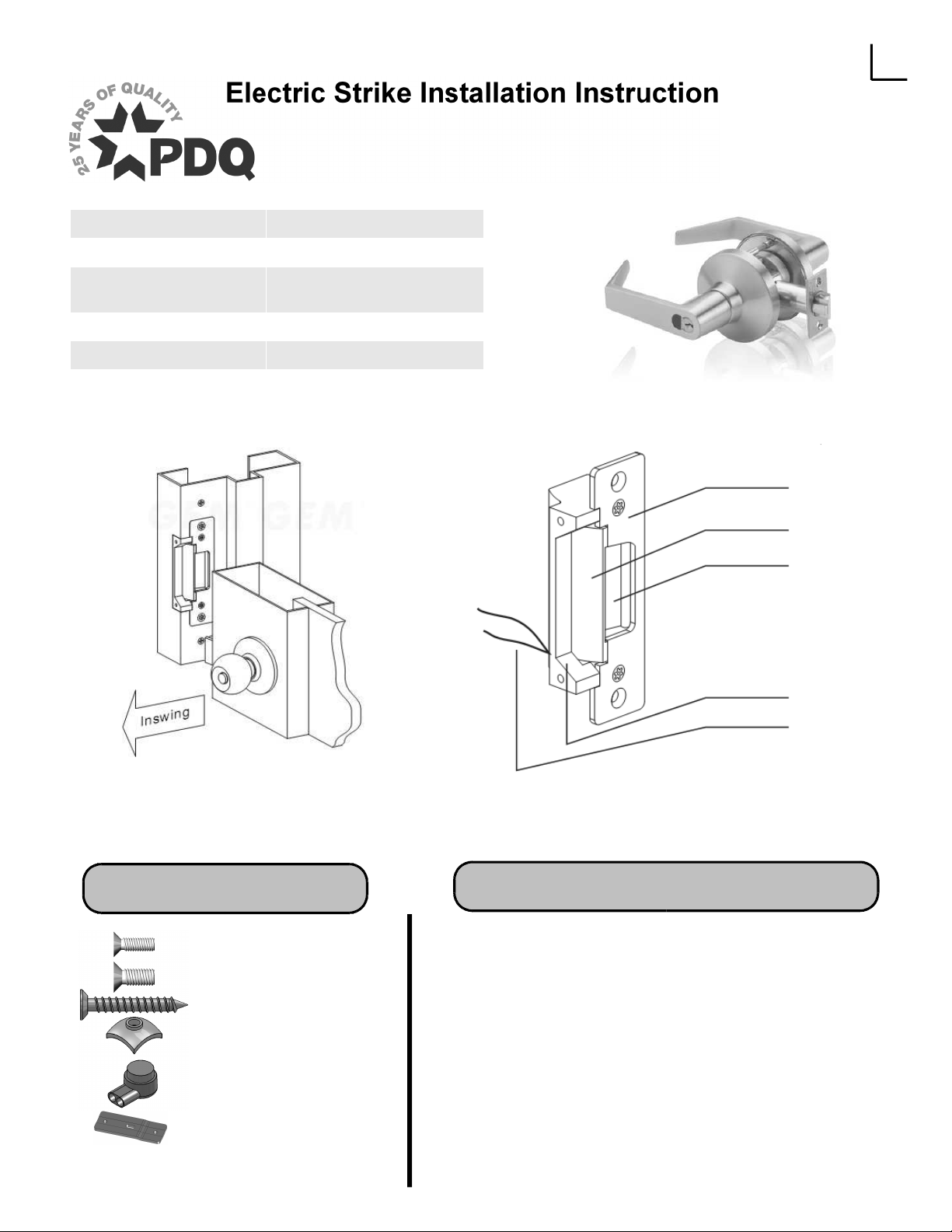
For PDQ GR1 and GR2 Cylindrical
Locks
Current Draw
Operating Temperature 14 – 110 degrees F
Humidity 0-95%
0.25A/12VDC
0.15A/24VDC
Faceplate
Door Stop
Latch Opening
Base
85101
REV 0
6/30/11
Included Hardware
2 x M4x0.7 Screw(s)
4 x M5x0.8 Screw(s)
2 x 1-1/4 Wood Screw(s)
2 x M4x0.7 Nut(s)
2 x Butt Splice
Connector(s)
2 x Support Bracket(s)
Cable
Installation Instructions
1. Verify that the strike is in the proper mode of operation
(Fail Secure/ Fail Safe). Refer to page 3
2. Prepare frame using the appropriate template for your
frame type. Refer to page 2
3. Connect the strike to power source. Refer to page 3
4. Install the strike unit in jamb cutout using the hardware
provided. Refer to page 2
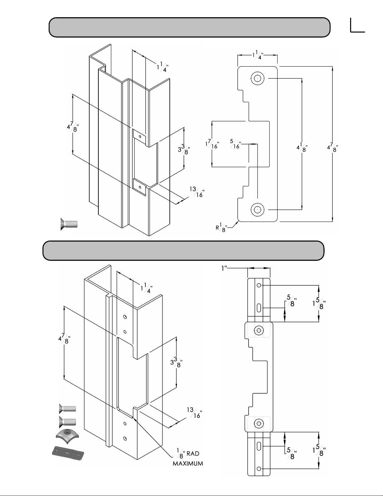
ANSI Metal Jamb Installations
2
(4) M5x0.8
Aluminum Jamb Installations
(2) M4x0.7
(4) M5x0.8
(2) M4x0.7 Nut
(2) Support
85101
REV 0
6/30/11

Changing Fail-Safe / Fail-Secure
3
Fail Secure
Apply Power to Open
Strike is shipped from factory in fail-secure configuration. If fail-safe configuration is desired, remove
screw from hole #1 as shown in above diagram and loosen screw #2. Slide screw #2 to opposite end of
the slot and tighten. Install screw #1 into hole labeled fail safe.
Fail Safe
Apply Power to Lock
Wiring Diagram
Single Voltage (12v or 24v)
Power
Supply
Control Device
(e.g. Reader)
12vDC/24vDC
85101
REV 0
6/30/11
N.C. Contact or Access Relay for “Fail-safe” setting
N.O. Contact of Access Relay for “Fail-secure” setting
Dual Voltage (12v or 24v)
Connect wires in Parallel for the 12vDC operation.
Black Black
Red
Black
Red Red
Connect wires in Series for the 24vDC operation.
Black Black
Red
Black
Red Red
12vDC
24vDC
 Loading...