

Page 1
WALL/CEILING
EXHAUST FANS
Models 6402, 6502, 6602
OPERATING INSTRUCTIONS
WALLEXHAUST-PDL-0704-L
IN-LINE EXHAUST FANS
6401 4” IN-LINE EXHAUST FAN
6501 5” IN-LINE EXHAUST FAN
6601 6” IN-LINE EXHAUST FAN
WALL/CEILING EXHAUST FANS
6402 4” WALL/CEILING EXHAUST FAN
6502 5” WALL/CEILING EXHAUST FAN
6602 6” WALL/CEILING EXHAUST FAN
ACCESSORIES (not included)
6412 4” THROUGH WALL KIT
– Includes: Square grille surround, Angled fixed grille,
Gravity Louvres, Aluminium Ducting (115mm
compacted, 320mm extended).
6512 5” THROUGH WALL KIT
– Includes: Square grille surround, Angled fixed grille,
Gravity Louvres, Aluminium Ducting (115mm
compacted, 320mm extended).
6612 6” THROUGH WALL KIT
– Includes: Square grille surround, Angled fixed grille,
Gravity Louvres, Aluminium Ducting (115mm
compacted, 320mm extended).
6312 ELECTRONIC TIMER (FOR IN-LINE EXHAUST
FANS ONLY)
– Adjustable time : 3 to 20 minutes, Max Load : 150W
6322 ELECTRONIC TIMER (FOR WALL/CEILING
EXHAUST
FANS ONLY)
– Adjustable time : 3 to 20 minutes, Max Load : 150W
SPARES
GRILLES
6401G 4” IN-LINE ROUND GRILLE
6501G 5” IN-LINE ROUND GRILLE
6601G 6” IN-LINE ROUND GRILLE
DUCTING
6401D 4” IN-LINE DUCTING 3m
6501D 5” IN-LINE DUCTING 4m
6601D 6” IN-LINE DUCTING 6m
MOTORS
6401M 4” IN-LINE MOTOR
6501M 5” IN-LINE MOTOR
6601M 6” IN-LINE MOTOR
PDL EXHAUST FAN RANGE
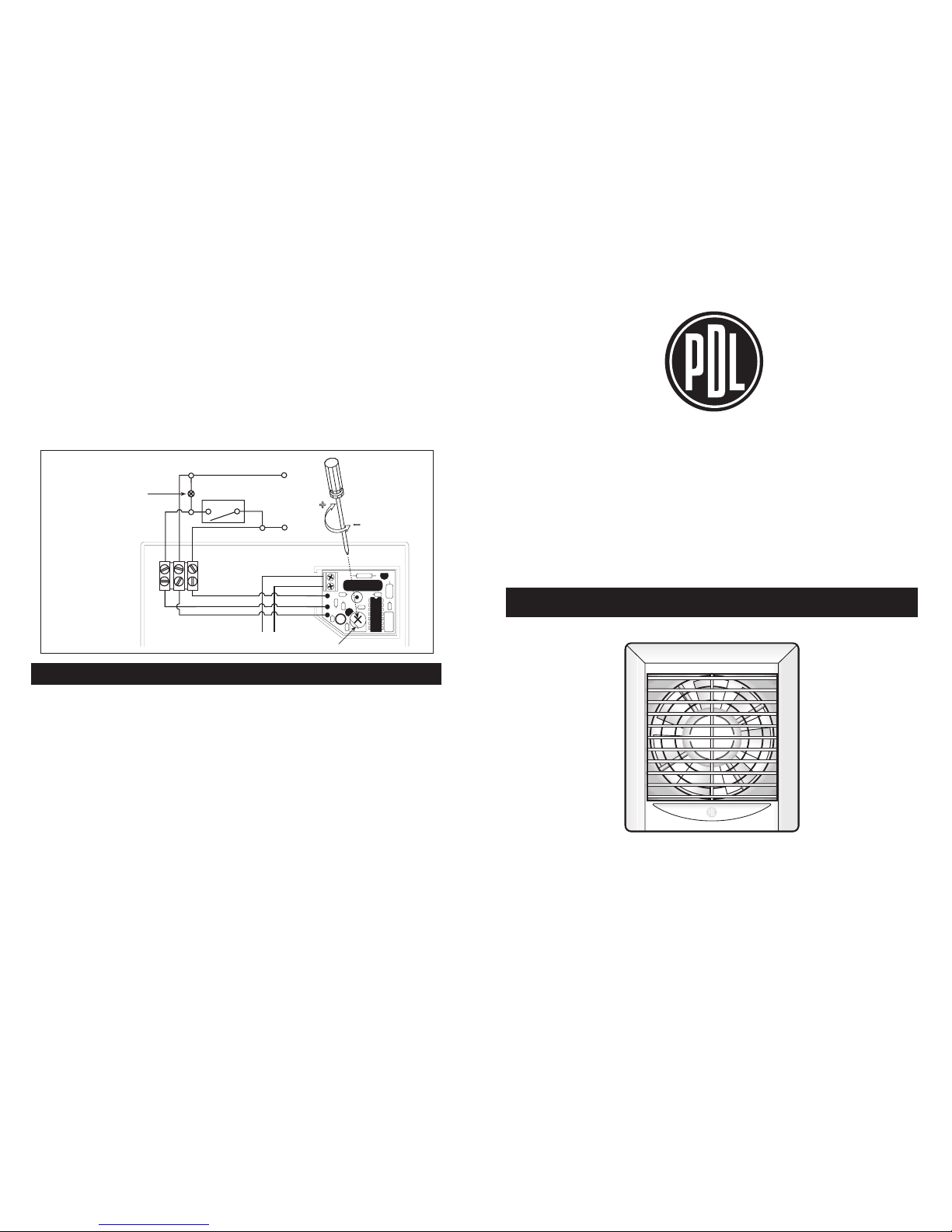
FITTING AND WIRING PDL 6322 TIMER ACCESSORY (Not included)
1. Remove screw cover and front grille from fan motor housing.
2. Remove 2 motor wires from terminal block and re-connect to electronic board as shown in Wiring Diagram 2.
3. Connect the remaining electronic board and mains supply wires to terminal block and trigger switch as shown
in Wiring Diagram 2. Ensure mains supply cable is fixed with the cable fastener.
4. Position electronic board into fan motor housing.
5. The timer can be pre-set from 3 to 20 minutes by adjusting the trimmer (only adjust with all supply circuits
switched off).
6. Screw on electronic board cover and replace front grille and screw cover.
NOTE: The fan will automatically start up 20 seconds after light or trigger switch is on and will continue to operate
for the time pre-set after the light or trigger switch is turned off. (Max. load of timer is 150W).
LIGHT CONNECTION
(optional)
WIRING DIAGRAM 2
TRIMMER
L
PHASE
(Brown)
SWITCHED PHASE
(Black)
NEUTRAL
(Blue)
PHASE
(Brown)
T N L
TRIGGER SWITCH
(Not included)
NEUTRAL
(Blue)
MOTOR
WIRES
Page 2
TEMPLATE
CENTRE POINT 6402 6502 6602
110mm 130mm 160mm (DIA. HOLES)
B
• Precautions must be taken to avoid the back-flow of gases into the room from the open flue of gas or
other open-fire appliances.
• This fan should not be used for the extraction of combustible gases or vapour.
• WARNING: Before obtaining access to terminals, all supply circuits must be disconnected.
• The appliance is not intended for use by young or infirm persons without supervision.
• Young children should be supervised to ensure that they do not play with the appliance.
• Ensure that a suitable disconnection switch is installed in the fixed wiring, in accordance with the local
wiring rules and regulations.
• Do not install within 120cm of a stove.
GENERAL INFORMATION
SPECIFICATIONS
MODEL
6402 6502 6602
Ducting Diameter(mm/inches) 100/4” 120/5” 150/6”
Duty At Free Discharge (m
3
/h) 85 130 230
Nominal Air Flow Pressure (mmH2O) 0.65 0.30 0.80
Voltage 230-240 Volts 230-240 Volts 230-240 Volts
Frequency 50Hz 50Hz 50Hz
Wattage 11 15 29
Sound Pressure Level At 1.5m db (A) 44 46 50
Insulation Class II II II
Protection IPX2 IPX2 IPX2
Max Running Temperature 40°C40°C40°C
INSTALLATION INSTRUCTIONS
INSTALLATION
IMPORTANT: This fan unit must be installed according to the latest Local Electrical Code of Practice.
1. Remove all parts from the packaging.
2. Locate an internal area (indoor wall or ceiling) to place the unit ensuring that the area is free from
obstruction and is between two studs or joists. NB: Do not mount fan unit directly over a shower cubicle.
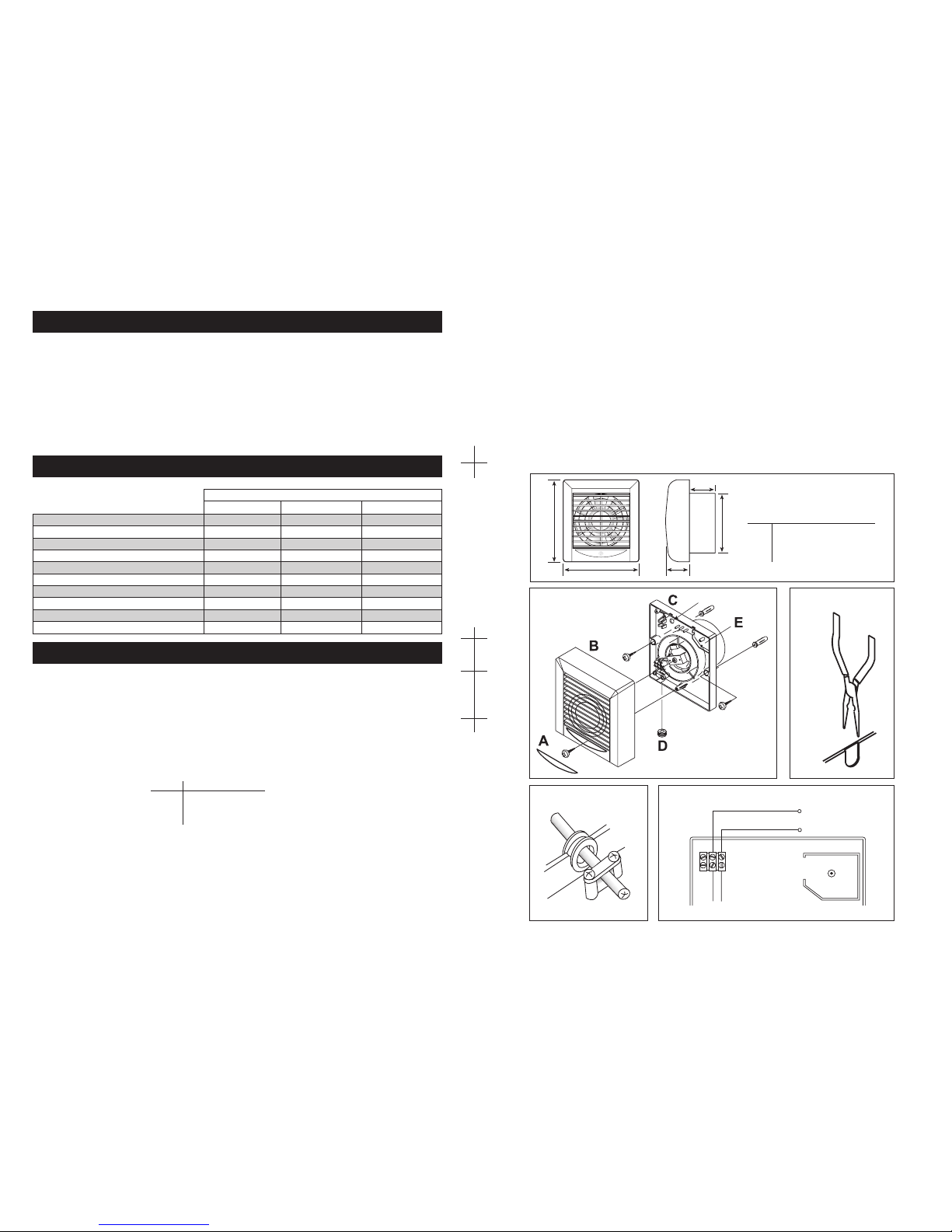
3. Dismantle the unit as shown in Figure 1.
4. Place motor housing ‘C’ on location chosen and draw an outline around the outlet (or aluminium ducting
if Through Wall kit to be fitted ie: extra 5mm to radius of circle).
Alternatively, use this card as a template for marking appropriate hole size.
Approx. dimensions are: Model Cut hole diameter
6402 110mm
6502 130mm
6602 160mm
5. Cut out the outline using a suitable tool.
6. Fix motor housing ‘C’ to the chosen location using the screws and wall plugs provided or by other suitable
means.
WIRING
Note: All wiring must be securely fixed and the supply cable must be a minimum of 1mm2 in section and
maximum cable outside diameter is to be 7mm. All wiring must comply with the current regulations.
IMPORTANT: Switch off mains supply before making any electrical connections.
Figure 1 Figure 2
SUPPLY CABLE ENTRY HOLE
Option 1: A. Cut a cable entry on the motor housing ‘C’ and front grille ‘B’ with a pair of long nose pliers
as shown in Figure 2 and insert cable seal ‘D’.
B. Pass supply cable through the cable seal ‘D’ and fix the cable with the cable fastener as shown
in Figure 3.
Option 2: A. Punch out a knockout hole on motor housing and trim edges with a file.
B. Drill a hole in wall or ceiling in line with knockout hole and pass supply cable through.
STANDARD MODELS (Wiring Diagram 1)
1. Ensure screw cover and front grille are removed from fan motor housing.
2. Connect the mains supply as shown in Wiring Diagram 1.
3. Fix the front grille ‘B’ on the fan motor housing ‘C’ with screw.
4. Fit screw cover ‘A’ on the front grille ‘B’.
PHASE
(Brown or Red)
NEUTRAL
(Blue or Black)
T N L
MOTOR WIRES
Wiring Diagram 1Figure 3
A
D
C
E
Dimensions (mm)
Cat No. A B C D E
6402 164 154 42 46 98
6502 184 174 42 46 118
6602 230 200 52 63 148
Option 2: Knock out hole
(Option 1)
(Option 1)
(NB: the fan motor unit must only be mounted indoors)
 Loading...