

PDL 4HS1200WH, 4HS1400WH, 4HS1200SS, 4HS1400SS, 4JH1200WH Installation Manual
...
Installation Guide
PDL Thermosafe Ceiling Sweep Fans
4HS1200WH, 4HS1400WH, 4HS1200SS, 4HS1400SS, 4JH1200WH,
4JH1400WH, 4JH1200SS, 4JH1400SS
IMPORTANT NOTES
1. To ensure proper balance, the blades are a matched set. Do
notmix-up the blades with those from another fan.
2. Transport and transit handling may loosen factory fitted cables.
Please check and secure terminal screws before installation.
PM-119PDLA Rev0
Thank you for purchasing this PDL Thermosafe Ceiling Sweep Fan. You can be assured of years of trouble free operation by
installing your ceiling fan carefully according to these instructions. Please read all the instructions before commencing, then
complete each step in order from one to eight.
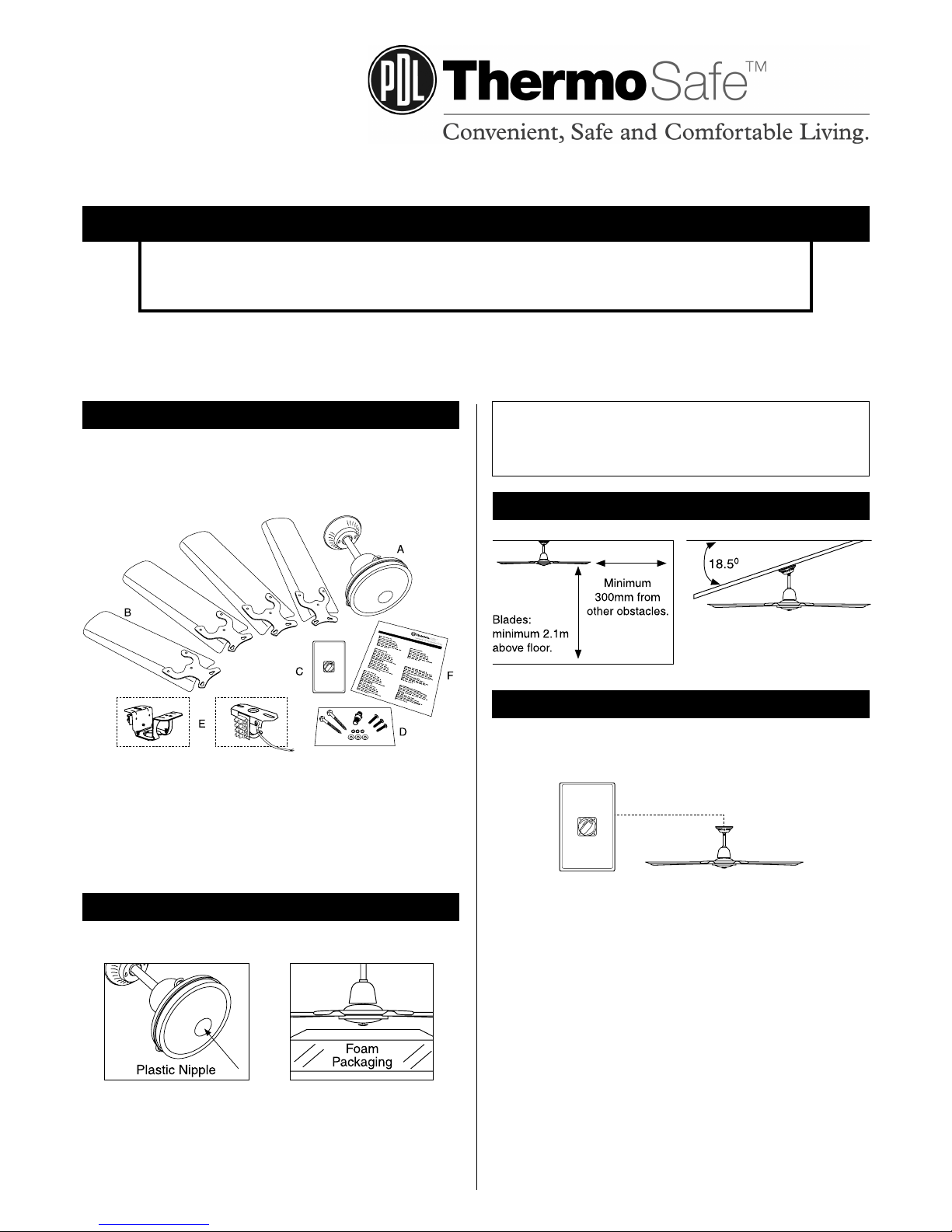
INCLUDED WITH YOUR FAN
A. Motor Assembly
B. 4 x Blades
C. 3-Speed Fan Controller
D. Screw Pack
E. Mounting Bracket
F. Instruction Sheet
Hangsure Bracket or J-Hook Bracket
PROTECTING THE FAN
Do not place the motor directly onto a flat surface.
The plastic nipple underneath the motor cannot support the weight
of the motor and may be easily damaged. When w orking on the
fan, place the motor on the foam packaging with the nipple located
in one of the recesses. This protects the nipple and the finish.
All electrical work must be carried
out by a qualified electrician.
CLEARANCES AND ANGLED CEILINGS
Hangsure Mounting
Suitable for pitched ceilings
with a maximum angle of 18.5˚.
CONTROLLING A SINGLE FAN
This fan has been supplied with a quality PDL 3 Speed Controller
that is designed to operate a single fan.
1
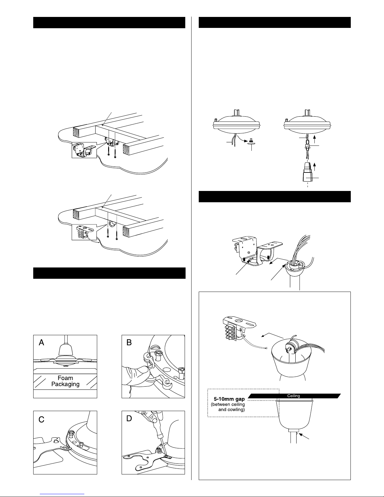
1. MOUNTING THE FAN SUPPORT BRACKET
Select a suitable location to mount the fan support bracket.
The mounting bracket must be fixed to a solid structural member
such as a ceiling joist or a securely fixed noggin and be capable of
supporting 15 Kg.
Additionally it must be located so as to provide the blade with a
minimum clearance from the floor of 2100mm, and from other
obstructions of at least 300mm.
Hangsure Mounting
J-Hook Mounting
Secure fixing to support 15kg
Secure fixing to support 15kg
2. FITTING THE BLADES
Discard the plastic spacer as illustrated in the diagram below.
Seat the key-slot holes of the blade on the screws of the fan motor.
Slide the blade to the right as illustrated until the blade engages in
the locking mechanism and secure the blade with screws.
Slide up top cowl but allow 5-10mm clearance. Secure with locking
screws.
Support the Motor Remove Plastic Spacer
Slide Blade over Screws Tighten Screws
2
3. CONNECTION OF THE LIGHT FITTING
If you are attaching a light fitting to the fan, do so prior to hanging
the fan. Note that Clipper Light (CL) and Oyster Light (OL) may be
installed in fans which are constructed for this purpose.
1. Unscrew the plastic nipple from the bottom of the motor housing.
2. Pull out the light wires from the motor housing for connection
with the lamp holder.
3. Insert the light wires through the adaptor, then screw the adaptor
into the motor shaft.
4. Connect the light wires to the lamp holder then screw the lamp
holder and the adaptor together firmly.
Light Wires
Plastic Nipple
Lamp Holder
Light Wires
Adaptor
4. HANGING THE FAN
Hangsure Bracket
Position the ball-joint in the bracket so that the guide pin on the
bracket engages in the slot in the ball-joint.
Guide Pin
Slot
J-Hook Bracket
Fit the rubber wheel assembly over mounting
Cowling
Screw
IMPORTANT NOTES
For J-Hook Brackets leave a 5-10mm gap between the ceiling
and cowling. It’s normal for the cowling to move slightly when
the fan is running. This gap prevents damaging the painted
ceiling and prevents ticking or clicking noises.
 Loading...