

Page 1
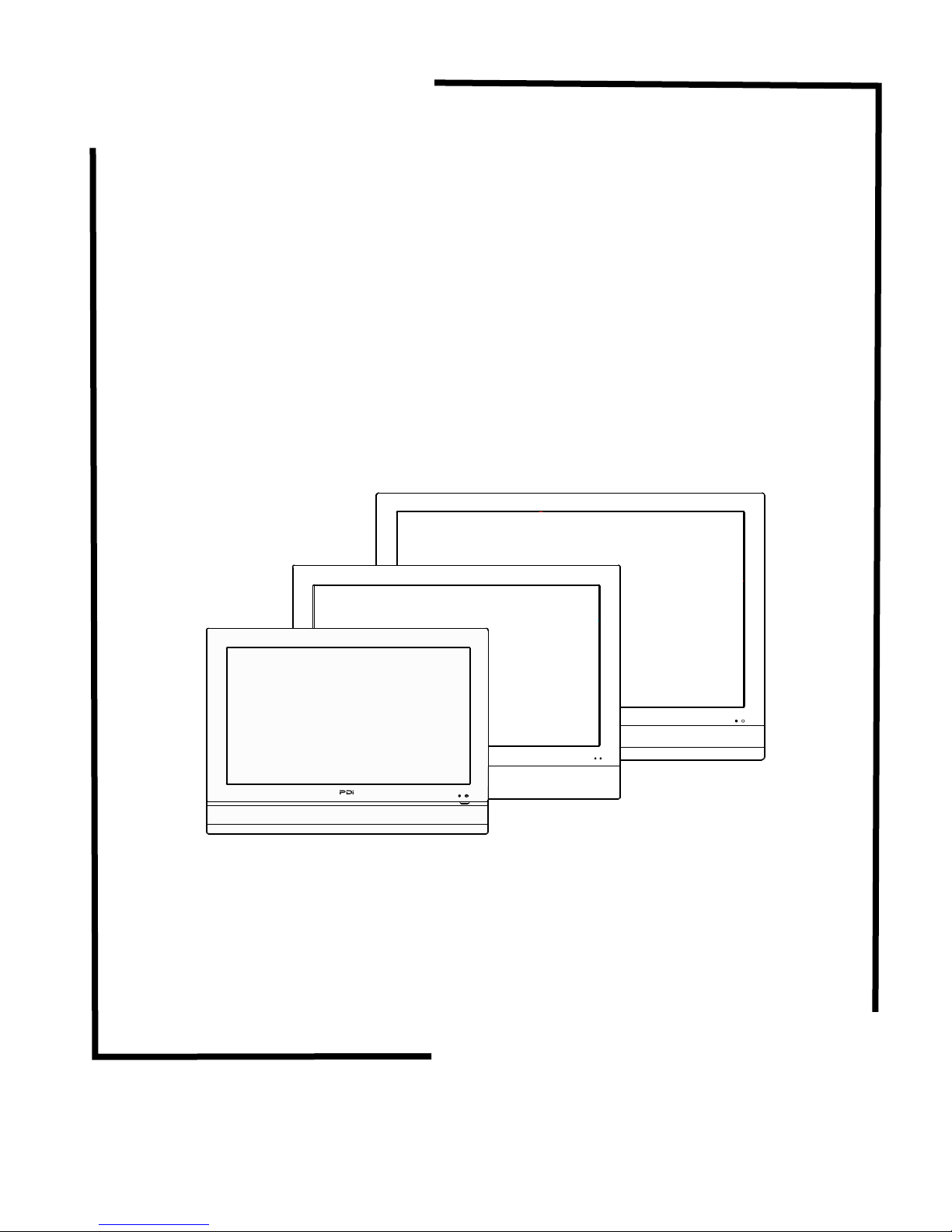
PDI-P26LCDC
PDI-P32LCDD
PDI-P40LCDC
Hospital Grade
Modular LCD Televisions
Quick Start Guide
Document Number: PD196-145R1
Page 2
Communication
Systems Inc.
CAUTION
RISK OF ELECTRIC
SHOCK
DO NOT OPEN !
MODEL NUMBER: PDI-P26LCDC, P32LCDD, P40LCDC DOCUMENT NUMBER: PD196-145R1
DESCRIPTION:
Modular TV Quick Start Guide
PAGE 2
Healthcare Grade Television
e PDI Healthcare series television is specically designed for installation
and use in a healthcare environment. e TV’s special design and safety
features have been investigated by the Underwriters Laboratory and
Listed for use in Hospitals, Nursing Facilities, Dialysis Clinics, and similar
healthcare services.
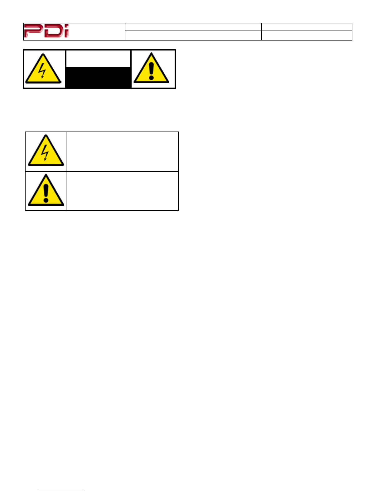
CAUTION: TO REDUCE THE RISK OF ELECTRIC SHOCK
DO NOT REMOVE COVER (OR BACK)
NO USER SERVICEABLE PARTS INSIDE
REFER SERVICING TO QUALIFIED SERVICE PERSONNEL
This lightning ash with arrowhead symbol
within an equilateral triangle is intended to
alert the user to the presence of uninsulated
dangerous voltage within the product’s
enclosure that may be of sufcient magnitude to
constitute a risk of electric shock to persons.
The exclamation point within an equilateral
triangle is intended to alert the user to
the presence of important operating and
maintenance (servicing) instructions in the
literature accompanying the product.
WARNING: To reduce the risk of re or electric shock, do
not expose this apparatus to rain or moisture.
WARNING: To prevent injury, this apparatus must be
securely attached to the oor/wall in accordance with the
installation instructions.
WARNING: Do not install this equipment in a conned
space such as a bookcase or similar unit.
CAUTION: Do not block ventilation openings. Install in
accordance with the manufacturer’s instructions.
REGULATORY INFORMATION
FCC Part 15
is equipment has been tested and found to comply with the limits for a
Class B digital device, pursuant to Part 15 of the FCC Rules.
ese limits are designed to provide reasonable protection against harmful
interference in a residential installation. is equipment generates, uses
and can radiate radio frequency energy and, if not installed and used in
accordance with the instructions, many cause harmful interference to radio
communications.
However, there is not guarantee that interference will not occur in a
particular installation. If this equipment does cause harmful interference
to radio or television reception, which can be determined by turning
the equipment o and on, the user is encouraged to try to correct the
interference by one or more of the following measures:
• Reorient or relocate the receiving antenna.
• Increase the separation between the equipment and receiver.
• Connect the equipment into an outlet on a circuit dierent from
that to which the receive is connected.
• Consult the dealer or an experienced radio/TV technician for help.
SERVICING
User Servicing
If your product is not operating correctly or exhibits a marked change in
performance and you are unable to restore normal operation by following the
detailed procedure in its operating instructions, do not attempt to service it
yourself as opening or removing covers may expose you to dangerous voltage
or other hazards. Refer all servicing to qualied service personnel.
Damage Requiring Service
Unplug this product from the wall outlet and refer servicing to qualied
service personnel under the following conditions:
• When the power supply cord or plug is damaged.
• If liquid has been spilled, or objects have fallen into the product.
• If the product has been exposed to rain or water.
• If the product does not operate normally by following the operating
instructions. Adjust only those controls that are covered by the
operating instructions as an improper adjustment of other controls
may result in damage and will oen require extensive work by a
qualied technician to restore the product to its normal operation.
• If the product has been dropped or damaged in any way.
• When the product exhibits a distinct change in performance which
indicates a need for service.
Replacement Parts
When replacement parts are required, be sure the service technician has
used replacement parts specied by the manufacturer or have the same
characteristics as the original part. Unauthorized substitutions may result in
re, electric shock, or other hazards.
Safety Check
Upon completion of any service or repairs to this product, ask the service
technician to perform safety checks to determine that the product is in safe
operating conditions.
Cleaning & Disinfecting
• Unplug the TV Before Cleaning.
• Use a so damp cloth to clean.
• Do not use harsh chemicals such as solvents.
• Wipe o water droplets from the cabinet and screen as soon as pos-
sible as they may leave spots.
Modications
Any changes or modications made to this device that are not expressly approved by PDI may void the user’s authority to operate the equipment.
Cables
Connections to this device must be made with shielded cables with metallic
RFI/EMI connector hoods to maintain compliance with FCC Rules and
Regulations.
Page 3
Communication
Systems Inc.
MODEL NUMBER: PDI-P26LCDC, P32LCDD, P40LCDC DOCUMENT NUMBER: PD196-145R1
DESCRIPTION:
Modular TV Quick Start Guide
PAGE 3
IMPORTANT SAFETY INSTRUCTIONS
1. Read these instructions.
2. Keep these instructions.
3. Heed all warnings.
4. Follow all instructions.
5. Do not use this apparatus near water.
6. Clean only with dry cloth.
7. Do not block any ventilation openings. Install in
accordance with the manufacturer’s instructions.
8. Do not install near any heat sources such as
radiators, heat registers, stoves, or other apparatus
(including ampliers) that produce heat.
9. Do not defeat the safety purpose of the polarized
or grounding-type plug. A polarized plug has two
blades with one wider than the other. A grounding
type plug has two blades and a third grounding
prong. e wide blade or the third prong are
provided for your safety. If the provided plug does
not t into your outlet, consult an electrician for
replacement of the obsolete outlet.
10. Protect the power cord from being walked
on or pinched particularly at plugs, convenience
receptacles, and the point where they exit from the
apparatus.
11. Only use attachments/accessories specied by the
manufacturer.
12. Use only with the cart, stand, tripod, bracket, or table specied by the
manufacturer, or sold with the apparatus. When a cart is used, use caution when moving the cart/apparatus
combination to avoid injury from tip-over.
13. Unplug this apparatus during lightning storms or
when unused for long periods of time.
14. Refer all servicing to qualied service personnel.
Servicing is required when the apparatus has been
damaged in any way, such as power-supply cord or
plug is damaged, liquid has been spilled or objects
have fallen into the apparatus, the apparatus has
been exposed to rain or moisture, does not operate
normally, or has been dropped.
15. is appliance should be mounted to a wall or
ceiling only as recommended by the manufacturer.
16. Care should be taken so that objects do no fall
and liquids are not spilled into the enclosure through
openings.
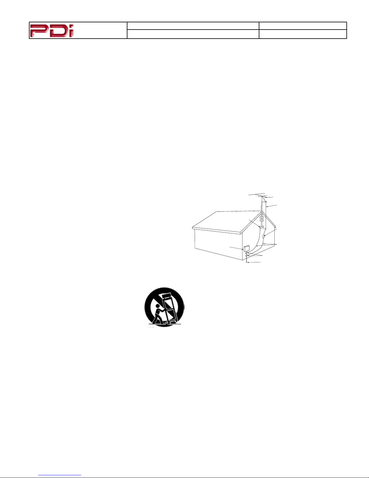
17. If an outside antenna or cable system is
connected to the video product, be sure the antenna
or cable system is grounded so as to provide some
protection against voltage surges and built-up static
charges. Section 810 of the National Electrical Code,
ANSI/NFPA 70, provides information with respect
to proper grounding of the mast and supporting
structure, grounding of the lead-in wire to an antenna
discharge unit, size of grounding conductors, location
of antenna-discharge unit, connection to grounding
electrodes, and requirements for the grounding
electrode. See Figure A.
NEC – NATIONAL ELECTRICAL CODE
ANTENNA
LEAD IN
WIRE
GROUND
ELECTRIC
SERVICE
EQUIPMENT
FIG . A
CLAMP
ANTENNA
DISCHARGE UNIT
(NEC SECTION 810 – 20)
GROUNDING CONDUCT ORS
(NEC SECTION 810 – 21)
GROUND CLAMPS
POWER SERVICE GROUNDING
ELECTRODE SYSTEM
(NEC ART 250, PART H)
NOTE: is reminder is provided to call the CATV
system installer’s attention to article 820-40 of the
NEC that provides guidelines for proper grounding
and, in particular, species that the cable ground
shall be connected to the grounding system of the
building, as close to the point of cable entry as
practical.
Page 4
Communication
Systems Inc.
MODEL NUMBER: PDI-P26LCDC, P32LCDD, P40LCDC DOCUMENT NUMBER: PD196-145R1
DESCRIPTION:
Modular TV Quick Start Guide
PAGE 4
INSTALLATION
LOCATION GUIDELINES
e model PDI-P26/P32/P40LCD Hospital Grade LCD TV is a specialized LCD TV. It is intended for
entertainment and educational purposes in a hospital, a nursing home, medical-care center, or similar
healthcare facility in which installation is limited to a non-hazardous area in accordance with the National
Electrical Code, ANSI/NFPA 70. e PDI-P26/P32/P40LCD is designed for mounting to PDI manufactured
mounts. Installation of the TV on any other brand of mount should follow the manufacturer’s mounting
specications.
TV MOUNT SELECTION
PDI Communication System Wall Mounts
PDI designed mounts are 100% compatible and available through your PDI distributor. Please refer to the
listings below for selection of a compatible mount. Detailed installation instructions are provided with each
mount.
TV MODEL WALL MOUNT DESCRIPTION
P26LCDC PD168-203
PD181-701
PD181-707
P32LCDD PD168-033
PD181-707
P40LCDC PD168-033
PD181-707
Standard Tilt Bracket
Articulating Wall Mount
Articulating Wall Mount
Standard Heavy Duty Tilt Bracket
Articulating Wall Mount
Standard Heavy Duty Tilt Bracket
Articulating Wall Mount
2nd Party Wall Mounts
PDI modular LCD televisions utilize the international VESA mounting standard used by other mount
manufacturers. It is important to select a mount designed to accommodate the TV’s weight, range of motion,
and VESA pattern. e listing below provides data to assist with selection. NOTE: PDI Communication
Systems strongly recommends contacting the mount manufacturer to verify compatibility.
TV MODEL WEIGHT VESA PATTERN MOUNTING HOLES
P26LCDC 33 lbs. 100 MM 4 MM read
P32LCDD 49 lbs. 200 MM 6 MM read
P40LCDC 61 lbs. 200 MM 6 MM read
WARNING: e TV’s VESA metric mounting holes are designed for metric M4
(P26LCDC) or M6 (P32LCDD, P40LCDC) metric screws only. Use of a nonPDI mount or SAE hardware could result in a condition where the TV could
unexpectedly fall and cause injury or death.
Page 5
Communication
Systems Inc.
MODEL NUMBER: PDI-P26LCDC, P32LCDD, P40LCDC DOCUMENT NUMBER: PD196-145R1
DESCRIPTION:
Modular TV Quick Start Guide
PAGE 5
WIRING
AC POWER & SIGNAL
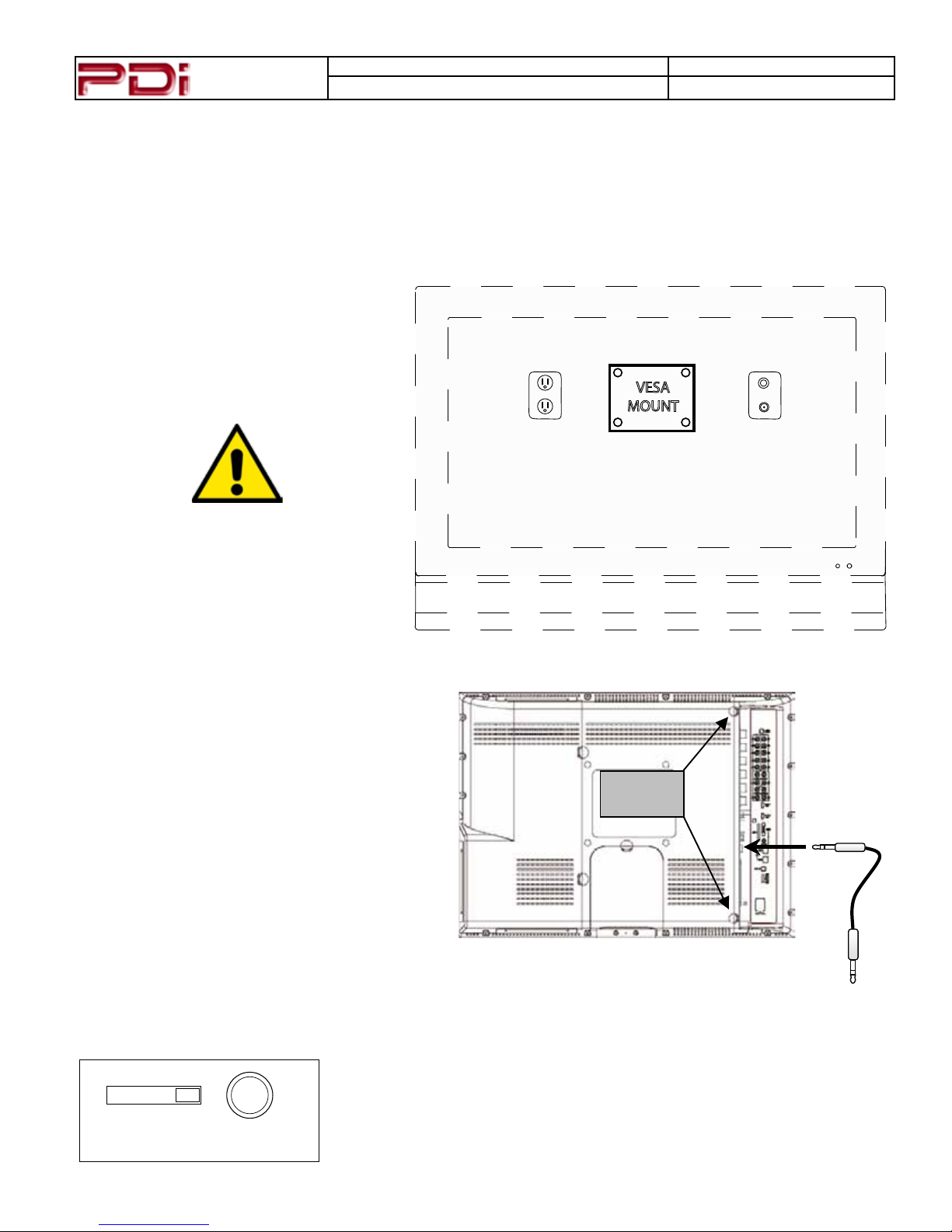
e PDI-P26/P32/P40LCD TV mounts on the wall at the foot of a patient’s bed. Select a location that is near
an AC wall outlet and that does not expose the TV to bright room lights or sunlight, if possible. e LCD TV
also requires connection of both CATV cable signal and across-room wiring for the pillow speaker.
NOTE: Do NOT locate the AC wall
outlet, CATV Signal Connector outlet, or
Pillow Speaker Jack wall outlet below the
VESA Mount wall location as it may cause
clearance issues and interfere with the TV’s
cabinet.
VESA
MOUNT
CAUTION: Some hospital cable systems
provide power voltage on the coaxial
cable. is TV is not designed to be powered via a coaxial cable. DO NOT connect to a powered coaxial cable. Damage
will result to the TV.
PILLOW SPEAKER
Depress the umb Tabs on the rear cabinet cover
and remove the cover. A ¼” stereo-style pillow
speaker (pendant control) jack is located on the
TV’s connector panel on the backside. is TV
is designed to work with either a digital pillow
speaker that generates digital-style control codes
or a single-button analog (switch-style) pillow
speaker. A rear panel mounted switch allows use
of dierent brands of pillow speakers and supports
the major brands: Zenith, Philips, and RCA.
THUMB
TABS
CR OFF CP CZ
PILLOW
TV CONNECTION
To Wall Plate
Pillow Speaker
Connection
e TV’s Pillow Speaker Selector switch should be congured for the type
of pillow speaker. ree dierent settings are available and listed below.
CR = RCA Pillow Speaker Codes
OFF = Disable Pillow Speaker Control
CP = Philips Pillow Speaker Codes
CZ = Zenith Pillow Speaker Code
Page 6

Communication
Systems Inc.
MODEL NUMBER: PDI-P26LCDC, P32LCDD, P40LCDC DOCUMENT NUMBER: PD196-145R1
DESCRIPTION:
Modular TV Quick Start Guide
PAGE 6
WIRING - Continued
Across-Room Wiring
e bed side pillow speaker control connects to the TV via a 3-wire interface cable (not supplied). A pin-out
of the signal connections is detailed on the optional jumper cables. PDI oers 2 dierent styles of jumper
cables as shown and must be ordered separately.
SPEAKER
DATA / SWITCH
COMMON
¼” to ¼” Jumper Cable
PD106-417
DATA / SWITCH
¼” to 6-Pin Jumper Cable
PD106-416
SPEAKER
COMMON
WARNING: DO NOT connect the pillow speaker common to earth ground.
Grounding of the common will defeat the isolation circuitry of the television
and possibly expose the patient to shock currents should a wiring fault occur.
Page 7
Communication
Systems Inc.
MODEL NUMBER: PDI-P26LCDC, P32LCDD, P40LCDC DOCUMENT NUMBER: PD196-145R1
DESCRIPTION:
Modular TV Quick Start Guide
WIRING - Continued
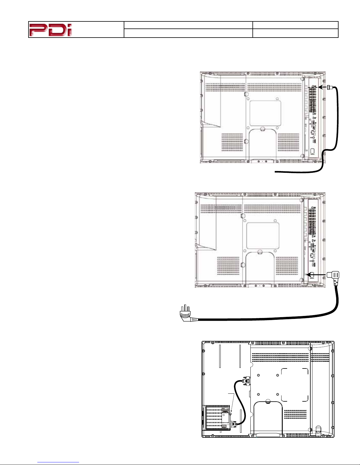
Coax Signal Cable
An F Style coax connection is provided on the TV’s side
panel for connection of the hospital cable TV signal coax.
AC Power Cord
A right angled AC power cord is supplied with each
T V.
PAGE 7
Hospital Cable TV Coax Cable
Connect the AC power cord into the TV’s AC jack
before connection the AC plug into a wall outlet.
Cable Routing
Route all cable through the access hole located in the
bottom corner.
en reinstall the back cover before operating the
T V.
Optional DVD Module
A DVD module is available as an option. e module
mounts inside the TV and is covered by a removable rear
access cover. Please see the instruction sheet packed with
the module for installation and setup instructions.
Attachment
Screw
Page 8
Communication
Systems Inc.
PROGRAMMING
Programming the TV involves accessing the internal setup menus, auto-programming
for channels, and setting up the TV’s sound.
A programming remote control (PD108-420) is required to perform all programming
setup operations. A programming remote control is not supplied with the TV and
MODEL NUMBER: PDI-P26LCDC, P32LCDD, P40LCDC DOCUMENT NUMBER: PD196-145R1
DESCRIPTION:
Modular TV Quick Start Guide
PAGE 8
POWER
SETUP
SLEEP
ARC
SUBPAGE
VOL
PSM
1
4
7
TEXT
HOLD
TV/FM
TV/AV
CH
OK
CH
SSM
2 3
5
8 9
SIZE
INDEX
MODE MIX UPDATE
MUTE
CH LIST
LAST
VOL
CC
SAP
*
6
0
REVEAL
must be order as an optional item.
PD108-420
Channel Setup
Programming Remote
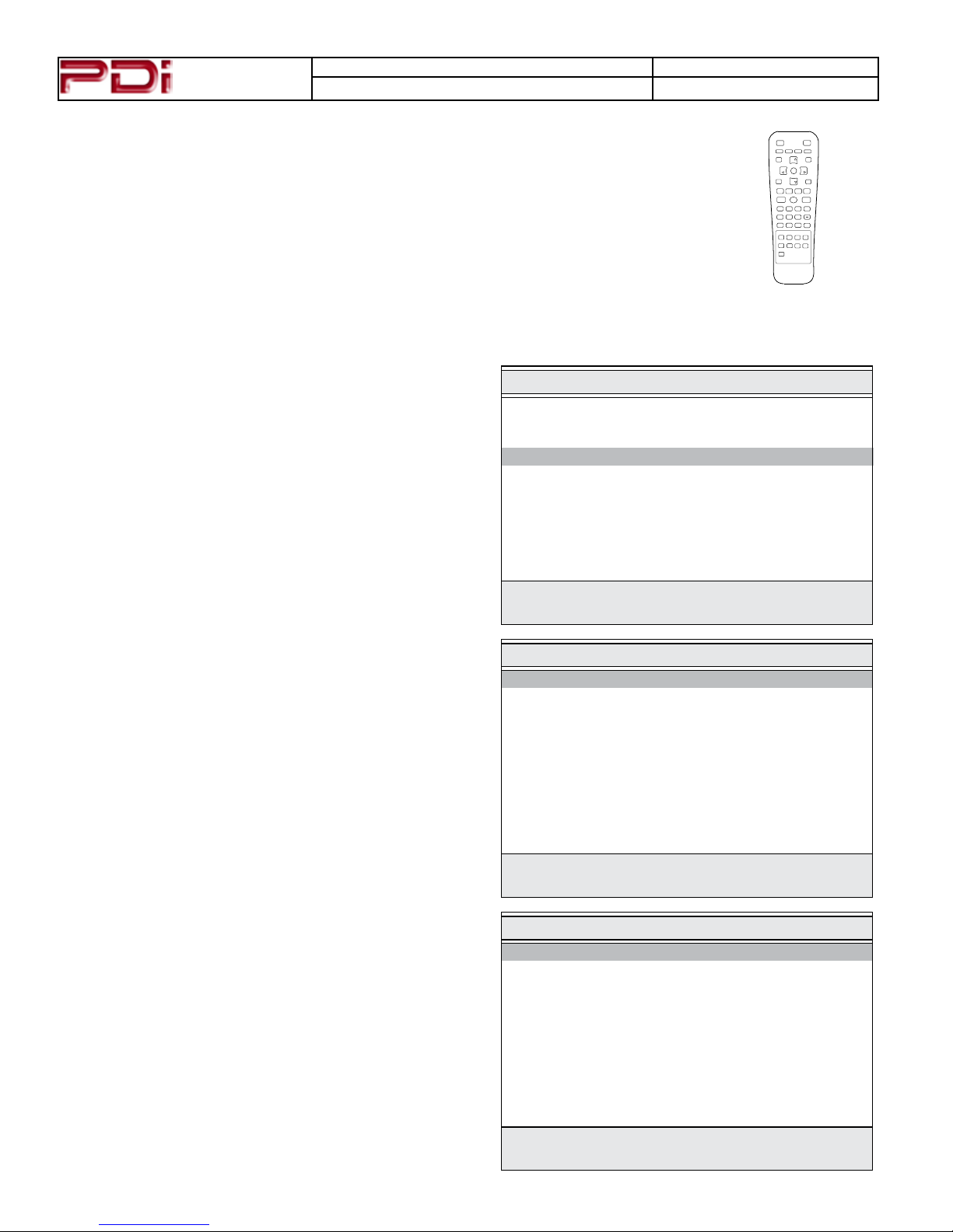
Connect the TV to a Cable TV signal before proceeding. Verify the handheld remote control operates the TV.
1. Press the setup button on the remote.
2. From the Setup menu, select Channels.
3. In the Channels menu, select Signal. Set the signal
to one appropriate to your healthcare facility. e possible choices are,
Cable STD Standard Cable TV
Cable IRC Incrementally Related Carrier
Cable HRC Harmonically Related Carrier
Air Air (Antenna)
4. In the Channels menu, select Auto Program.
5. In the Auto Program menu, select Mode. e TV
can be set to search and locate dierent styles of TV
signals; Analog Only, Digital Only, or both Analog
and Digital channels. Select the style of signal.
6. In the Auto Program menu, select Channel Se-
quence and select the manner in which channels are
viewed. e possible selections are:
Interleave A+D Analog and Digital appear grouped to-
gether
All A then D Analog appear rst, followed by Digital
7. e Additional Digital Signal selection allows for
auto programming of a second block of channels using
a dierent signal type. For example, rst Auto Program the TV for CATV STD signals, then use the Ad-
ditional Digital Signal set to AIR provides a second
auto programming of air type signals to be included
in addition to the channels found during normal Auto
Program searching into the same Service Level.
SETUP
■ Service Level Free
■ Picture ▶
■ Sound ▶
■ Channels ▶
■ Features ▶
■ OSD Language English
■ Sources ▶
■ FM Radio ▶
Position:
Exit: SETUP
Next:
Channel Setup
■ Signal Cable STD
■ Auto Program ▶
■ Add/Delete Channels ▶
■ Clear Service Level ▶
■ Copy Service Level ▶
■ Parental Control ▶
■ Power On Channel ▶
■ Channel Lock Disabled
■ Channel Memory Override Enabled
Position:
Exit: SETUP
Next:
Auto Program
■ Mode Analog Only
■ Channel Sequence Interleave A+D
■ Additional Digital Signal None
■ Free Programmed ▶
■ Basic Blank ▶
■ Premium Blank ▶
Position:
Exit: SETUP
Next:
Page 9
Communication
Conrm Auto Program
■ Conrmation ▶
Exit: SETUP
Yes
No
Systems Inc.
MODEL NUMBER: PDI-P26LCDC, P32LCDD, P40LCDC DOCUMENT NUMBER: PD196-145R1
DESCRIPTION:
Modular TV Quick Start Guide
PAGE 9
Channel Setup - continued
8. e TV oers 3 discrete groups of channels or
Service Levels. Free, Basic, or Premium can each
be programmed and used as needed. Select the desired
Service Level to program.
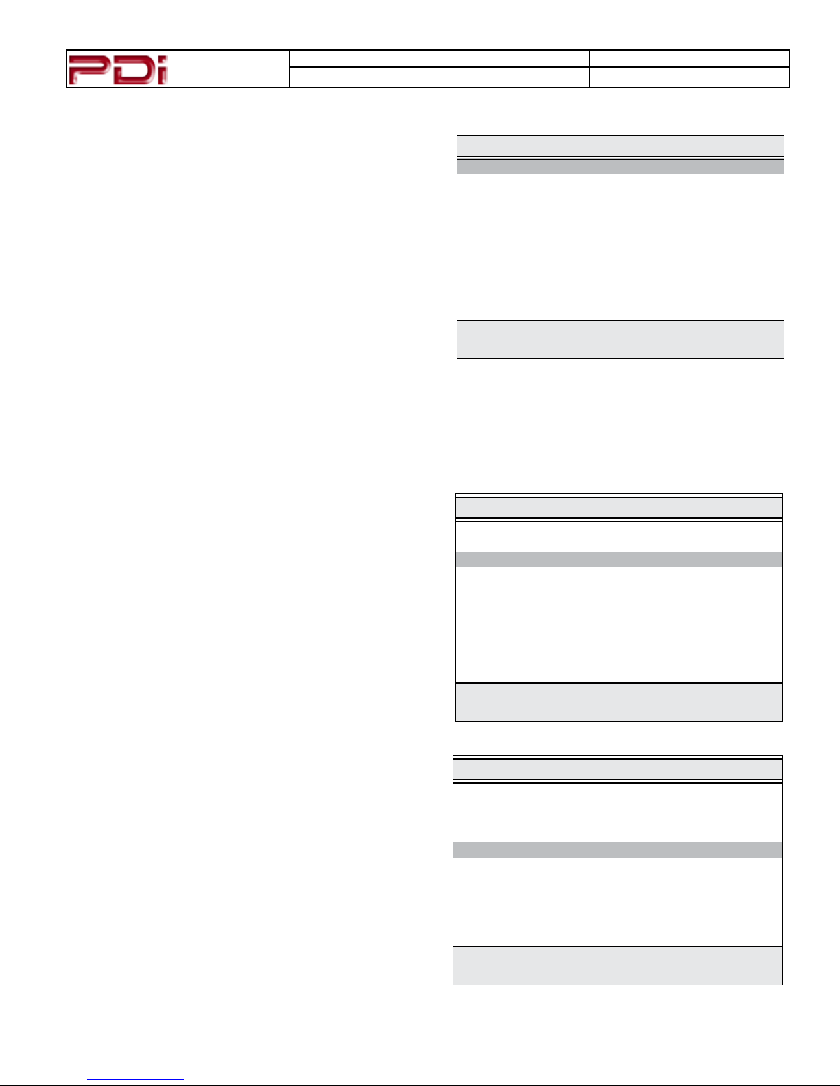
9. Press the Yes (Channel Up button) to begin Auto
Programing or No (Channel Down button) to exit.
Auto Programming takes approximately 2 to 12
minutes.
Pillow Speaker Sound Setup
Proper setup of the TV’s Sound is required for use with a wired Pillow Speaker. Setup involves disabling the
TV’s internal speakers and then setting the audio level to the pillow speaker.
1. Press the setup button on the handheld programming
remote control.
2. From the Setup menu, select Sound.
3. In the Sound menu, select Internal Speaker
Enable.
SETUP
■ Service Level Free
■ Picture ▶
■ Sound ▶
■ Channels ▶
■ Features ▶
■ OSD Language English
■ Sources ▶
■ FM Radio ▶
Position:
Exit: SETUP
Sound
■ Balance 0
■ Minimum Volume 0
■ Maximum Volume 100
■ Power On Volume Last
■ Internal Speaker Enable ▶
■ HDMI 1 Audio Port HDMI 1
■ HDMI 2 Audio Port HDMI 2
Next:
Position:
Exit: SETUP
Next:
Page 10
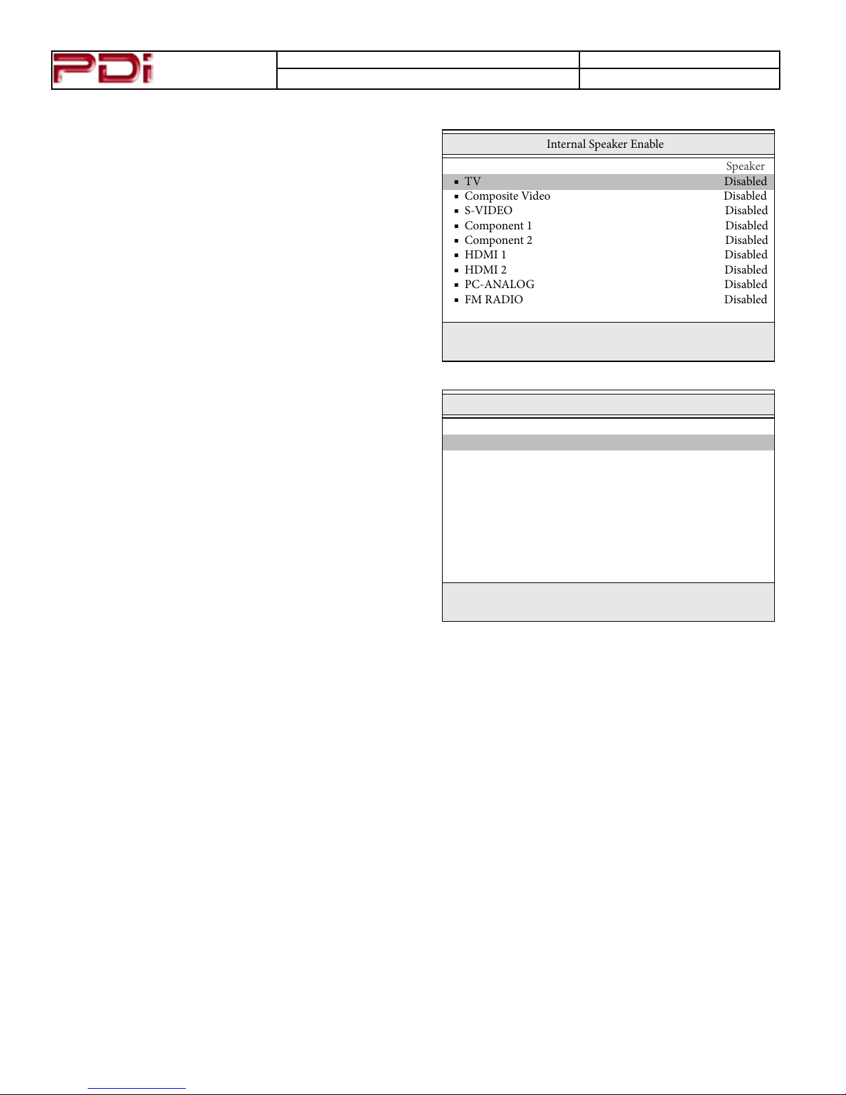
Communication
Internal Speaker Enable
Speaker
■ TV Disabled
■ Composite Video Disabled
■ S-VIDEO Disabled
■ Component 1 Disabled
■ Component 2 Disabled
■ HDMI 1 Disabled
■ HDMI 2 Disabled
■ PC-ANALOG Disabled
■ FM RADIO Disabled
Systems Inc.
MODEL NUMBER: PDI-P26LCDC, P32LCDD, P40LCDC DOCUMENT NUMBER: PD196-145R1
DESCRIPTION:
Modular TV Quick Start Guide
Pillow Speaker Sound Setup - continued
4. In the Internal Speaker Enable menu select the
source you wish to disable. For television select TV.
Position:
Exit: SETUP
PAGE 10
Next:
5. For Pillow Speakers with a thumb wheel volume con-
trol, in the Sound Menu, select Minimum Volume,
and set the level to approximately 50% to provide a
xed level of sound for the pillow speaker to adjust.
NOTE: Pillow Speakers with dedicated Volume Up
and Volume Down buttons do not require a Minimum
Volume adjustment.
■ Balance 0
■ Minimum Volume 50
■ Maximum Volume 100
■ Power On Volume Last
■ Internal Speaker Enable ▶
■ HDMI 1 Audio Port HDMI 1
■ HDMI 2 Audio Port HDMI 2
Position:
Exit: SETUP
Sound
Next:
ADDITIONAL USER INFORMATION
A full user manual is available on PDI Communication System’s Internet site. Please visit the document
library.
http://www.pdiarm.com
Page 11
Communication
Systems Inc.
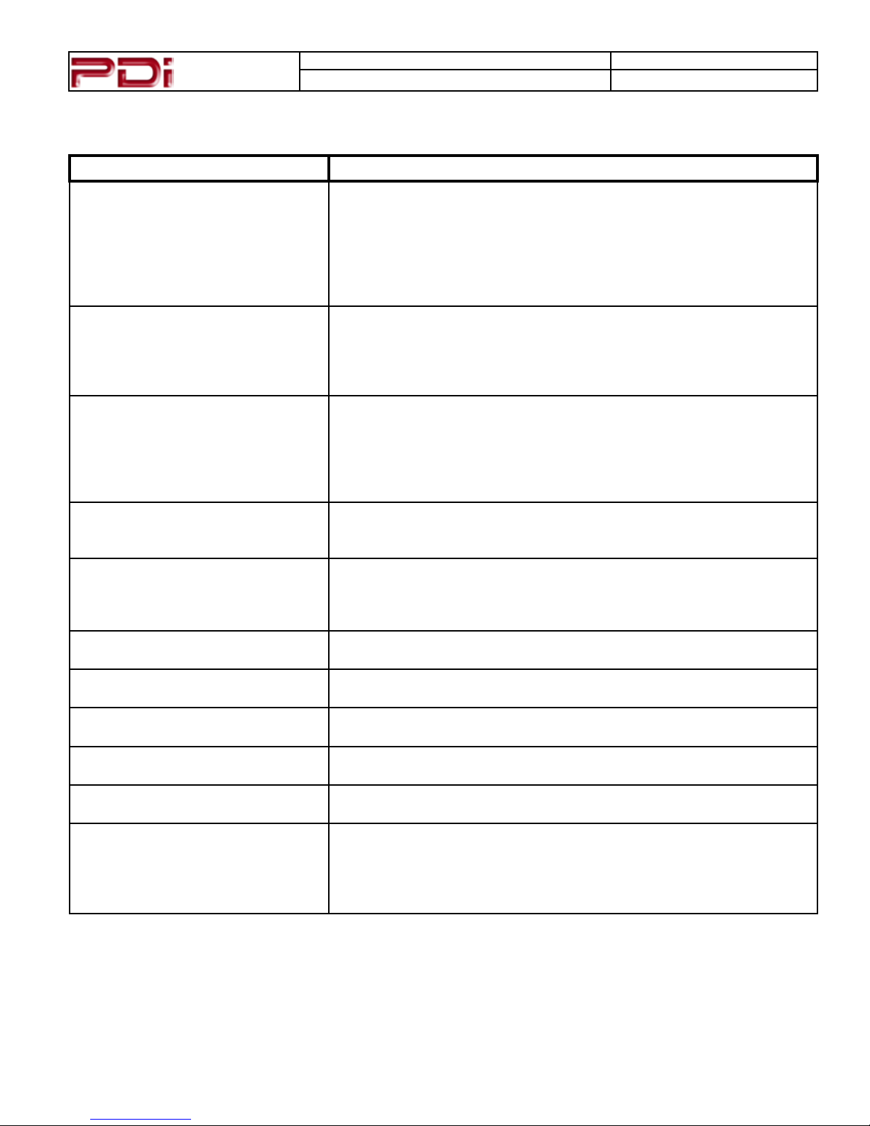
Troubleshooting
Problem CHECK
No Picture and No Sound
No Picture, Sound OK
Picture OK, No Sound
No Sound from Internal TV Speaker
Picture is too Light
Picture is too Dark
Picture Breaks-Up or Jitters
Picture has Ghost Images
Picture has Stripes or Dots
Pillow Speaker does not Control TV
Remote Control does not work
MODEL NUMBER: PDI-P26LCDC, P32LCDD, P40LCDC DOCUMENT NUMBER: PD196-145R1
DESCRIPTION:
Modular TV Quick Start Guide
PAGE 11
• Ensure the TV is connected to a powered AC outlet. The TV’s front
lamp will glow Red when correctly connected to power.
• Operate the TV directly by pressing the TV’s POWER button located on
the side of the cabinet.
• Try to cycle power to the TV by pulling the power cord from the AC
outlet, wait for 30 seconds, plug it back into the outlet, wait 15 seconds
or more and then try to turn On the TV again.
• Verify TV is set to an active Video Source or set directly to TV by pressing the TV/AV button on the side of the TV or the TV/AV button on the
remote control.
• If an Auxiliary Input Source is selected, verify the Video input signal
cable is connected and the video source is playing.
• Verify the Sound has not been muted.
• Check the Volume settings.
• Verify pillow speaker is connected and the volume control on the pillow
speaker is properly adjusted.
• If an Auxiliary Input Source is selected, verify the Audio input signal
cable is connected and the video source is playing.
• Verify the sound has not been muted.
• Verify the TV’s internal speakers have not been disabled in the “Internal
Speaker Enable” setup menu.
• Check that external light sources, such as windows or overhead lights
are not creating glare on the TV’s screen.
• Check the TV’s Brightness and Contrast settings in the TV’s Picture
menu.
• Check the TV’s Brightness and Contrast settings in the TV’s Picture
menu.
• Verify the coax cable is connected correctly.
• The cable TV signal may be too weak.
• The cable TV signal may be too weak.
• The coax cable connection may be loose.
• The cable TV signal may be too weak.
• The coax cable connection may be loose.
• Check the TV’s Pillow Speaker Selector switch is correctly set.
• Replace Pillow Speaker.
• Replace the remote’s batteries.
• VerifythatstronguorescentlightsarenotoodingtheTV’sIRwin-
dows
• For patient remote controls, verify remote is set to the correct Bed
Code.
Page 12
PDI Communication Systems, Inc.
40 Greenwood Lane
Springboro, Ohio 45066
 Loading...