

Page 1

PDI-P20LCDC
g
y
Hospital Grade
LCD Television
Rev 1
Please read this manual carefullybeforeoperatin
our set.
1 Document Number: PD196-103 Rev 1
User Manual
Page 2

Blank Page
2 Document Number: PD196-103 Rev 1
Page 3

A
WARNING
CAUTION :
user serviceable parts inside. Refer servicing to qualified service personnel.
To reduce the risk of electric shock do not remove cover (or back). No
This symbol is intended to alert the user of the presence of uninsulated ‘dangerous
voltage’
risk of electric shock to persons.
This symbol is intended to alert the userof the presence of importantoperating and
maintenance (servicing) instructions in the literature accompanying the appliance.
within the product’s enclosure that may be of sufficient magnitude to constitute a
NOTE TO CABLE TV INSTALLER
This reminder is provided to call the cable TV systems installer’s attention to Article 820-40 of
the National Electrical Code.
particular, specifies that the cable ground shall be connected to the grounding system of the
building, as close to the point of the cable entry as practical.
The code provides guidelines for proper grounding and, in
MAINTENANCE AND SERVICING
Never remove the back cover of the TV; this can expose you to high voltage and other hazards. If
the
TV does not operate properly, unplug it and call an authorized service center or PDI .
CLEANING AND DISINFECTION
Clean the exterior of this television by removing dust with a lint-free cloth.
CAUTION: To avoid damage to the surface of the television, do not use abrasive or chemical
cleaning agents.
RAIN AND MOISTURE
WARNING: To avoid the hazards of fire or electrical shock, DO NOT expose this
television to rain or moisture.
OXYGEN ENVIRONMENT
WARNING: Do not use in any oxygen tent or oxygen chamber. Such use may cause a
fire hazard.
WET LOCATION
pparatus shall not be exposed to dripping or splashing and no objects filled with liquids,
such as vases, shall be placed on the apparatus.
OVERHEAD FALLING HAZARD
TVs can pose a striking hazard when mounted at an elevated position.
mounting brackets and appropriate hardware to assure TV will not fall from the
mounted position. Failure to do so may cause injury or death.
Use only PDI
3 Document Number: PD196-103 Rev 1
Page 4

p
Warning
SERVICE INSTRUCTIONS
CAUTION: These servicing instructions are for use by qualified service personnel only.
To reduce the risk of electric shock, do not perform any servicing other than contained in the
o
erating instructions unless you are qualified to do so.
PRODUCT MODIFICATION
Do not attempt to modify this product in any way without written authorization. Unauthorized
modification could void the user’s authority to operate this product.
REGULATORY INFORMATION: FCC
This equipment has been tested and found to comply with the limits for a Class B digital device,
pursuant to part 15 of the FCC Rules.
against harmful interference when the equipment is operated in a residential or commercial installation.
If this equipment does cause harmful interference to radio or television reception, which can be
determined by turning the equipment off and on, the user is encouraged to try to correct the interference
by one of more of the following measures:
Reorient or relocate the receiving antenna.
•
Increase the separation between the equipment and receiver.
•
•
Connect the equipment into an outlet on a circuit different from that to which the receiver is
connected.
•
Consult the dealer or an experienced radio/TV technician for help.
These limits are designed to provide reasonable protection
UNDERWRITERS LABORATORIES
The model PDI-P20LCDC Hospital Grade LCD TV is a specialized LCD television. This TV is
intended for entertainment and educational purposes for use in a hospital, a nursing home, a
medical-care center, or a similar health care facility.
apparatus is to be grounded in accordance with the National Electrical Code,
This device is safety tested and listed by the Underwriters Laboratories as a
product suitable for use in health care facilities in both the United States and
Canada.
The antenna or cable system connected to an
ANSI/NFPA 70.
4 Document Number: PD196-103 Rev 1
Page 5

pyrig
A
Important Safety Instructions
Important safeguards for you and your new product
1. Read these instructions.
2. Keep these instructions.
3. Heed all warnings.
4. Follow all instructions.
5. Do not use this apparatus near water.
6. Clean only with dry cloth.
7. Do no block any ventilation openings. Install in
accordance with the manufacturer’s instructions.
8. Do not install near any heat source such as
radiators, heat registers, stove, or other apparatus
(including amplifiers) that produces heat.
9. Do not defeat the safety purpose of the hospital
grounding-type plug.
and a third grounding prong.
provided for your safety. If the provided plug does not
fit into your outlet, consult an electrician for
replacement of the obsolete outlet.
10.Protect the power cord from being walked on or
pinched particularly at plugs, convenience
receptacles, and the point where they exit from the
apparatus.
Co
A
hospital plug has two blades
The third prong is
ht, Disclaimer, & Trademarks
11. Only use attachments/accessories specified by the
manufacturer.
12. Use only with the cart, stand,
tripod, bracket or table
specified by the manufacturer,
or sold with the apparatus.
When a cart is used, use
caution when moving the
cart / apparatus combination to avoid injury from
tip-over.
13. Unplug this apparatus during lightning storms or
when unused for long period of time.
14. Refer all servicing to qualified service personnel.
Servicing is required when the apparatus has been
damaged in any way, such as power-supply cord or
plug is damaged, liquid has been spilled or objects
have fallen into the apparatus, the apparatus has
been exposed to rain or moisture, does not operate
normally, or has been dropped.
15. Use only PDI mounts and appropr iat e ha rd ware .
Failure to do so could cause the set to fall and
subsequent injury or death.
COPYRIGHT
PDI Communication Systems, Inc. claims proprietary right to the material disclosed in this user
manual.
anything shown herein. Copyright
This manual is issued for user information only and may not be used to manufacture
2007 by PDI Communication Systems, Inc. All rights reserved.
DISCLAIMER
The author and publisher have used their best efforts in preparing this manual. PDI
Communication Systems, Inc. make no representation or warranties with respect to the accuracy
or completeness of the contents of this manual and specifically disclaim any implied warranties or
merchantability or fitness for any particular purpose and shall in no event be liable for any loss of
profit or any other damages.
warranted, and is subject to change without notice or obligation.
The information contained herein is believed accurate, but is not
TRADEMARKS
ll brand names and product names used in this manual are trademarks, registered trademarks,
or trade names of their respective holder. PDI and Better Solutions
registered trademarks of PDI Communication Systems, Inc., Springboro, Ohio.
5 Document Number: PD196-103 Rev 1
Are Within Reach are
Page 6

Contents
WARNINGS
REGULATORY INFORMATION
Important Safety Instructions………………………………………………………………………………………………..…..5
Copyright …….……………………………………………………………………………………………………………...……5
Disclaimer………………………………………………………………………………………………………..………………..5
Trademarks …………….…………………………………………………………………………………………………...……5
Supplied Accessories…………………………………………………………………………………………………….……...8
Optional Accessories…………………………………………………………………………………………………………….8
Battery Installation ……………………………………………………………………………………………………………….8
CONTROLS
Front Panel……………………………………………………………………………………………………………9
Rear Panel………………………………………………………………………………………………………….. 10
Remote Control …….………………………………………………………………………………………………………11-12
INSTALLATION
Location Guidelines………………………………………………………………………………..……………….13
OSHPD (State of California Only)……………………………………………………………………..………….13
Cable System Grounding…………………………………………………………………………………..………13
Across-Room Wiring……………………………………………………………………………..…………………16
CONNECTIONS
Antenna “ANT” Connection………………………………………………………………………….…………….17
A/V IN………………………………………………………………………………………………….…….……….17
A/V OUT……………………………………………………………………………………………………………..18
S-Video Connection……………………………………………………………………………………………...…18
BASIC OPERATION
PICTURE
PC ANALOG PICTURE.
COMPONENT INPUT PICTURE
Temperature……………………………………………………………..………………………………………….28
ARC (Aspect Ratio Control)……………………………………………..………………………………………...28
H-Position (Horizontal Position)…………………………………………..……………………………………….28
V-Position (Vertical Position)………………………………………………..……………………………………..28
Note to Cable TV Installers………………………………………………………………………………………….3
Maintenance and Service……………………………………………………………………………………………3
Cleaning and Disinfection…………………………………………………………………………………………...3
Service Instructions………………………………………………………………………………………………..…4
Product Modification………………………………………………………………………………………………….4
FCC………………………………………………………………………………………………………………..…...4
Underwriters Laboratories………………………………………………………………………………………..….4
Wall Mounting on Wall Bracket……………………………………………………………….………….……14-15
Component 1 / Component 2 IN ………………………………………………………………………………….19
SPDIF ………………………………………………………………………………………………………………..20
Pillow Speaker …..…………………………………………………………………………………………………21
PC Connection ………………………………………………………………………………..……………………22
Turning the TV On and Off………………………………………………………………..……………………….23
Channel Selection ..………………………………………………………………………………………………..23
Volume Adjustment . ………………………………………………………………………………………………23
Last Channel ……..…………………………………………………………………………………………………23
Sound Mute Function ………….…………………………………………………………………………………..23
Sleep Timer ….……………………………………………………………………………………………………..23
On Screen Menu Language Selection …………………………………………………………..……………….24
Changing the Source Input ………………………………………………………………………..………………24
Service Level ..……………………………………………………………………………………..………………26
Color Temperature ……………………………………………………………………………..………………..…27
PC Analog Picture………………………………………………………………………………..…………………27
Temperature …..……………………..…….………………………………………………………………………27
Clock ……………………………………………..………………………………………………………………….27
Phase ……………………………………………..…………………………………………………………………27
Temperature ………………………………………..………………………………………………………………27
Clock ………………………………………………..……………………………………………………………….27
Phase ………………………………………………..………………………………………………………………27
ARC (Aspect Ratio Control) ………………………..……………………………………………………………..27
H-Position (Horizontal Position) …………………….…….………………………………………………………27
V-Position (Vertical Position) …..……………………………………..…………………………………………..27
6 Document Number: PD196-103 Rev 1
Page 7

Contents
SOUND CONTROL
Sound Status Memory…………………………………………………………………………………..……….…30
Balance………………………………………………………………………………………………..……………..30
AVL……………………………………………………………………………………………………..…………….30
Surround………………………………………………………………………………………………..……………30
Minimum Volume…………………………………………………………………………………………..………..31
Maximum Volume………………………………………………………………………………………….……….31
Power On Volume…………………………………………………………………………………….…………….31
Internal Speaker Enable………………………………………………………………………..…..……………...32
Composite / S-Video Sound Mode……………………………………………………………….……………….32
CHANNEL SETUP
Signal…………………………………………………………………………………………………………………33
Auto Program………………………………………………………………………………………………………..34
Add / Delete Channels……………………………………………………………………..….……………………35
Clear Service Level……………………………………………………………………………………………..…..37
Copy Service Level……………………………………………………………………………….…..…………….38
Parental Control……………………………………………………………………………………………………..39
PARENTAL CONTROL
TV Rating……………………………………………………………………………………………….…..………..40
MPAA Rating………………………………………………………………………………………..……………….41
Change Password………………………………………………………………………………….……………….42
Aux. Block Source………………………………………………………………………………….……………….42
Block Hour………………………………………………………………………………………….………………..42
Parental Lock ……………………………………………………………………………………………………….42
Motion Picture Association of USA (MPAA) Rating Chart………………………………….…………………..43
TV Parental Guideline Rating System………………………………………………………..…..………………43
SOURCE SETUP
Enabling / Disabling Sources………………………………………………………………………………………44
Power On Source ………………………………………………………………………………………………..…44
FEATURES
Power On Captions Mode …………………………………………………………………………………………45
Auto Power On………………………………………………………………………………………………………45
Power Management ………………………………………………………………………………………………..46
Bed A/B……………………………………………………………………………………………………….…..….46
Caption Text Modes…………………………………………………….…..………………………………………46
Digital Mode Time Setup ……………………………………………………..……………………………………47
Diagnostics…………………………………………………………………………..………………………………47
Channel Up Power Off………………………………………………………………..…….…..………………….48
Channel to Other Sources…………………………………………………………….…………………………...48
FM RADIO
FM Radio Setup…………………………………………………………………………………..…..….……...….49
Auto Program…………………………………………………………………………………………..……………49
Add / Delete Stations………………………………………………………………………………….……………49
SPECIFICATIONS………………………………………………………………………………………………….…………..50
TROUBLESHOOTING……………………………………………………………………………………………….………...51
LIMITED WARRANTY……………………………………………………………………………….………………………...52
Equalizer…………………………………………………………………………………………………..………....29
7 Document Number: PD196-103 Rev 1
Page 8
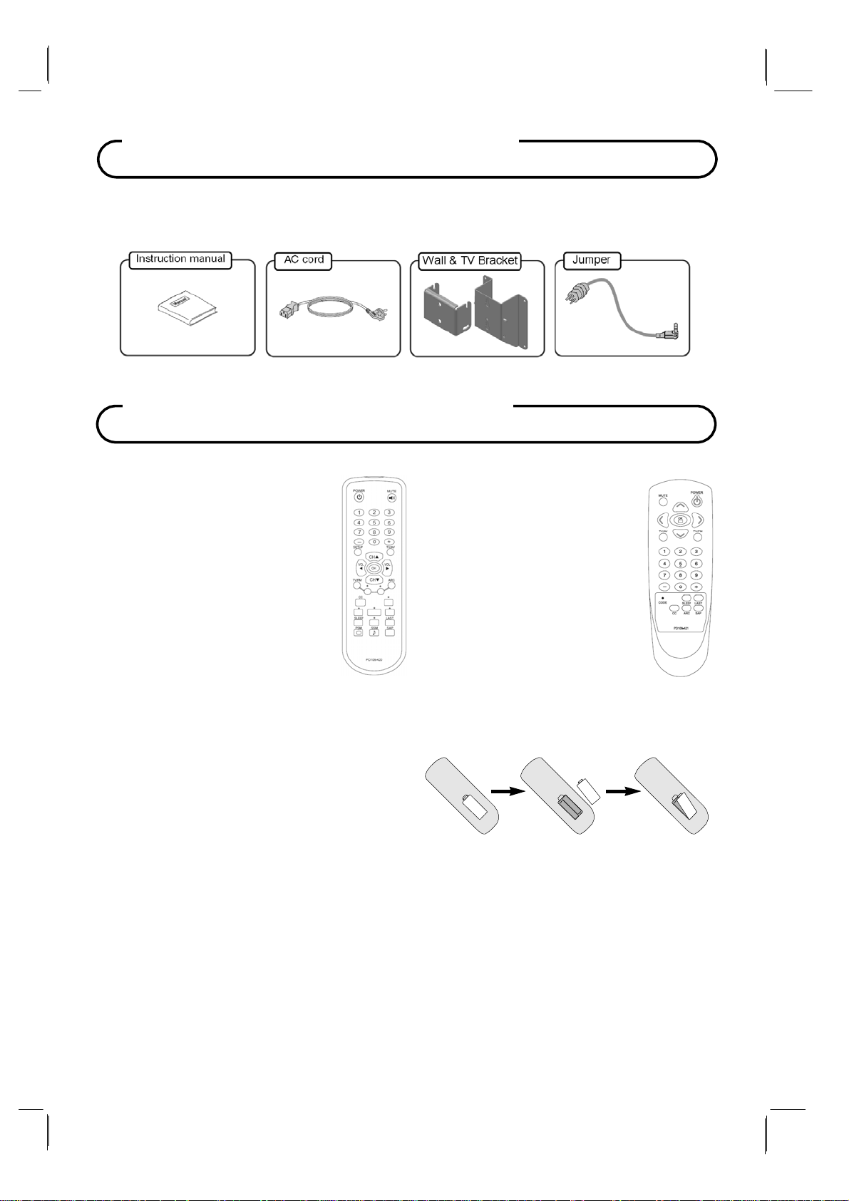
Supplied Accessories
Make sure the following accessories are provided with product.
Optional Accessories
Programming Remote
PD108-420
A programming remote control
is required to perform all TV
setup adjustments including
programming channels. The
remote is NOT included with the
TV and must be ordered
separately – one remote is
capable of programming an
entire hospital of televisions.
Please order programming
remote control part number
PD108-420.
PD108-420
Patient Remote
PD108-421
In addition to pillow speaker
control of the TV, a patient
remote control is also
available. The remote
offers independent Bed A
or Bed B selectable codes
and independent control of
a single television in a two
television room. Please
order patient remote control
part number PD108-421.
Battery Installation
Inserting batteries
1.
Remove the battery cover by pulling it
upward in the direction shown by the arrow.
Insert the batteries with correct polarity.
2.
3.
Replace the battery compartment cover.
Install two high-quality 1.5V "AAA" alkaline batteries. Don't mix old batteries with new
batteries.
Remove batteries when you won't use the remote controller for long time. Liquid leakage
from old batteries may cause operation failure.
PD108-421
Notes for using remote controller
Make sure there are no objects between the remote controller and its sensor.
Don't place the remote control near a heater or in damp place. Strong impact to the remote
control may cause operation failure.
Sunlight or other bright light may disturb the signal from the remote control. In this case,
darken the room or move the
8 Document Number: PD196-103 Rev 1
TV.
Page 9
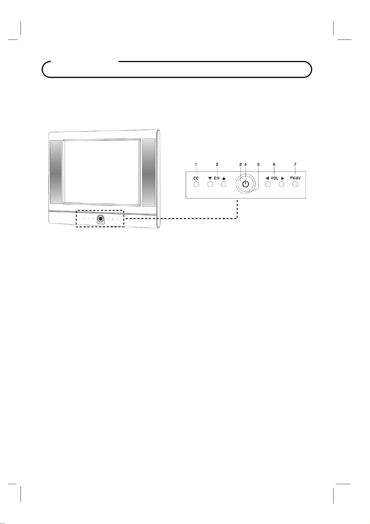
Controls
Front Panel
1.
CC
Sets the caption function.
▼
2.
3.
4.
5.
6. ◄
7.
CH ▲ (Channel Down / Up)
Selects a channel or a menu item.
Power Indicator
Illuminates in red when the TV is off.
Illuminates in green when the
ON / OFF
Switches TV set on or off.
Remote control sensor
Accepts the IR signal of remote controller.
VOL ► (Volume Down / Up)
Adjusts the volume. Adjusts menu settings.
TV / AV
Selects
the video
mode.
TV is switched on.
9 Document Number: PD196-103 Rev 1
Page 10
y
r
Control
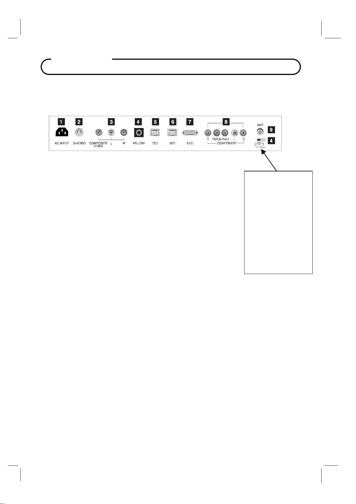
Rear Panel
1.
AC IN PU T
Power Cord connection jack.
S-VIDEO IN
2.
Connect the video output of an S -VIDEO VCR to the S-VIDEO input.
Connect the audio output to L and R jacks.
3. COMPOSITE VIDEO / AUDIO L, R IN
Connect the Audio / Video outputs of external equipment to these inputs.
4. PILLOW
Pillow speaker port.
Use the switch to select correct voltage.
CZ : Zenith Compatible (+14V)
CP : Philips Compatible (+5V)
CR : RCA
Compatible (-5V)
Off : Pillow port disable (0V)
5.
CCI
Communication port.
6.
MTI
Connection to MTI device.
7. SVC
Service port.
8.
COMPONENT IN
Connect the COMPONENT audio / video output sockets of the DVD to the
COMPONENT audio / video input sockets of the set.
9.
ANT
Connection to Cable TV Coax.
! CAUTION !
Moving this switch changes
the voltage supplied to the
pillow speaker.
Make sure it is set correctl
BEFORE plugging in the
pillow speaker jumpe
cable.
Failure to do so WILL
RESULT IN THE PILLOW
SPEAKER BEING
OVERDRIVEN AND
POSSIBLE DAMAGE TO
THE PILLOW SPEAKER.
10 Document Number: PD196-103 Rev 1
Page 11
R
T
/AV
Programming Remote Control
A programming remote control is required to perform all TV setup adjustments including
programming channels. The remote is NOT included with the TV and must be ordered
separately – one remote is capable of programming an entire hospital of televisions. Please
order programming remote control part number PD108-420.
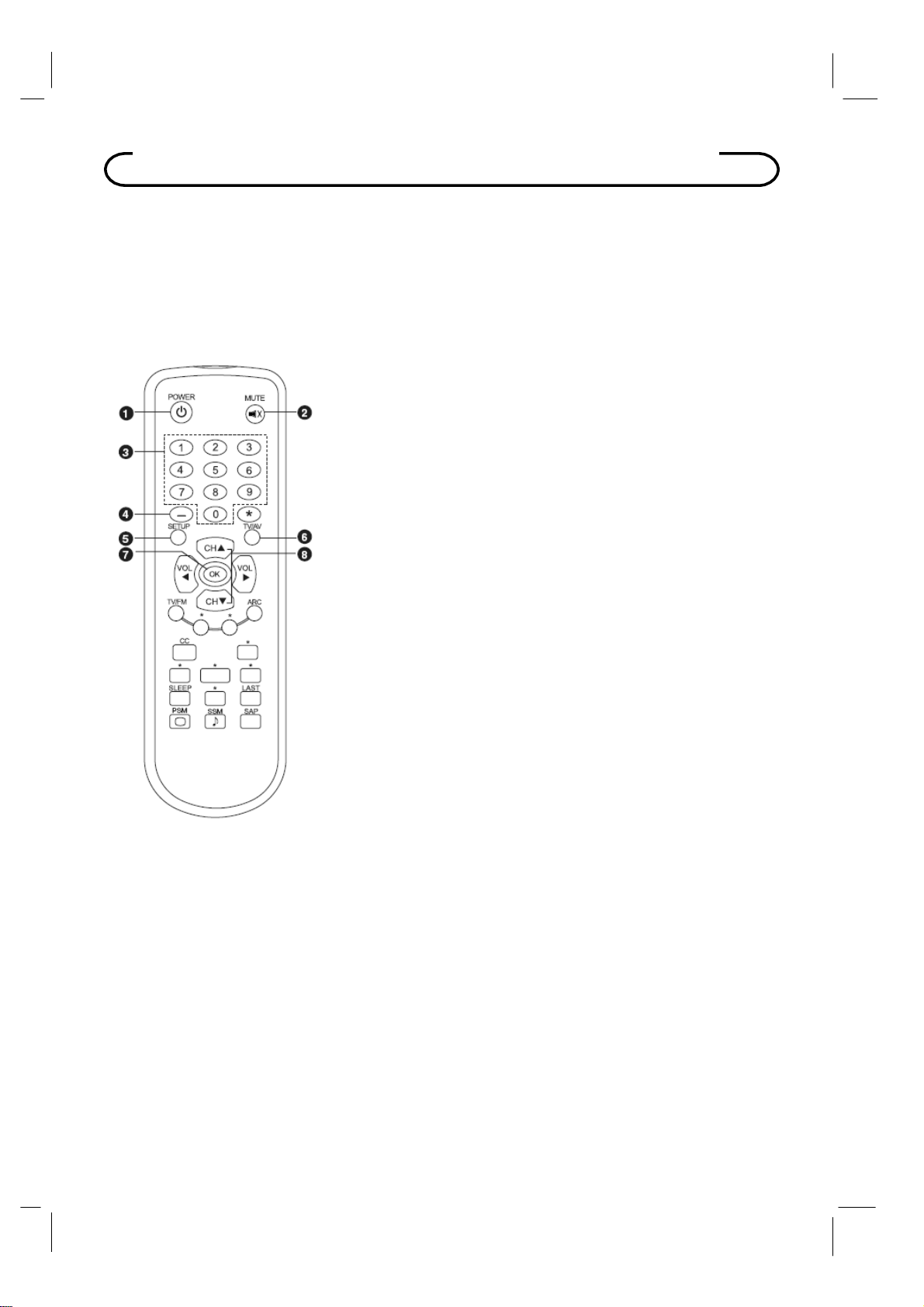
Remote Control
Before you use the remote controller,please install the batteries.
1
POWE
Turns the TV on or off.
2
MUTE
urns the sound on or off.
3
NUMBER buttons
Selects channel numbers.
4 Dash
Press to select DTV (Digital TV) channels.
For example, to select channel ‘54-3’, press ‘54’, then press ‘-’
and ‘3’.
5
SETUP
Displays the main menu.
Exit current OSD menu.
6
TV
Selects programmed external inputs.
7
OK
Accepts your channel selection. Displays digital channel
information.
8
CH ▲▼
Selects next channel or a menu item.
11 Document Number: PD196-103 Rev 1
(Channel Up / Down)
Page 12
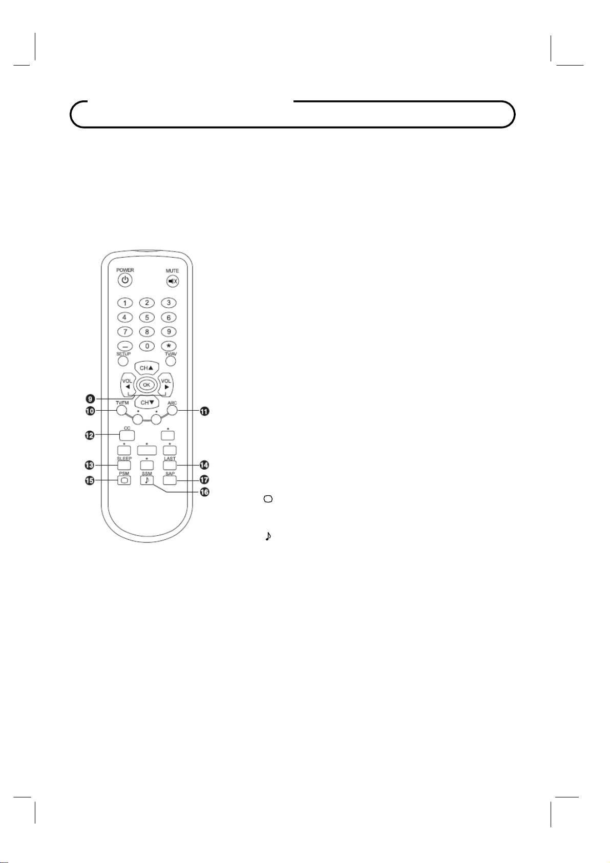
Remote Control
9
VOL
Adjusts the sound level.
Adjusts menu settings.
10 TV / FM
Selects the either TV or FM Radio mode directly.
11 ARC
Changes the aspect ratio.
Repeatedly press the ARC button to select your desired picture
format.
12 CC
Sets the caption function.
◄►
(Volume Up/Down)
13 SLEEP
Sets the sleeptimer.
14 LAST
Returns to thepreviouslyviewed channel.
15 PSM ( )
Recallsyourpreferredpicture setting.
16 SSM ( )
Recallsyourpreferred sound setting.
17 SAP
Adjusts the
audio mode for either
Stereo,Mono
, or SAP.
12 Document Number: PD196-103 Rev 1
Page 13

Installation
LOCATION GUIDELINES
The model PDI-P20LCDC Hospital Grade LCD TV is a specialized LCD television. This TV is
intended for entertainment and educational purposes for use in a hospital, a nursing home, a
medical-care center, or a similar health-care facility in which installation is limited to a nonhazardous area in accordance with the National Electrical Code, ANSI/NFPA 70. The PDIP20LCDC is designed for mounting to PDI manufactured mounts. Installation of the TV on any
other mount is not recommended.
The PDI-P20LCDC TV mounts at the foot of a patient’s bed. Select a location that is
near an AC wall outlet and that does not expose the TV to bright room lights or sunlight if
possible. The LCD TV also requires connection of both CATV cable signal and acrossroom wiring for the pillow speaker.
OSHPD (State of California Only)
The combined weight of the PDI-P20LCDC TV and PDI Standard Wall Mount totals less than
20 pounds. At the time of this writing, the involvement of a written, submitted, reviewed, and
approved plan by OSHPD is not required to install the PDI-P20LCDC TV in the state of
California.
CABLE SYSTEM GROUNDING
The coax cable system connected to the PDI-P20LCDC TV should be grounded in accordance
with the National Electrical Code, ANSI/NFPA 70. The code provides guidelines for proper
grounding and, in particular, specifies that the cable ground shall be connected to the
grounding system of the building, as close to the point of the cable entry as practical.
WARNING: The TV’s VESA mounting
holes are designed for M4 metric screws
only. Use of a non-PDI approved mount or
SAE hardware could result in a condition
where the TV could unexpectedly fall and
cause injury or death.
13 Document Number: PD196-103 Rev 1
Page 14
A
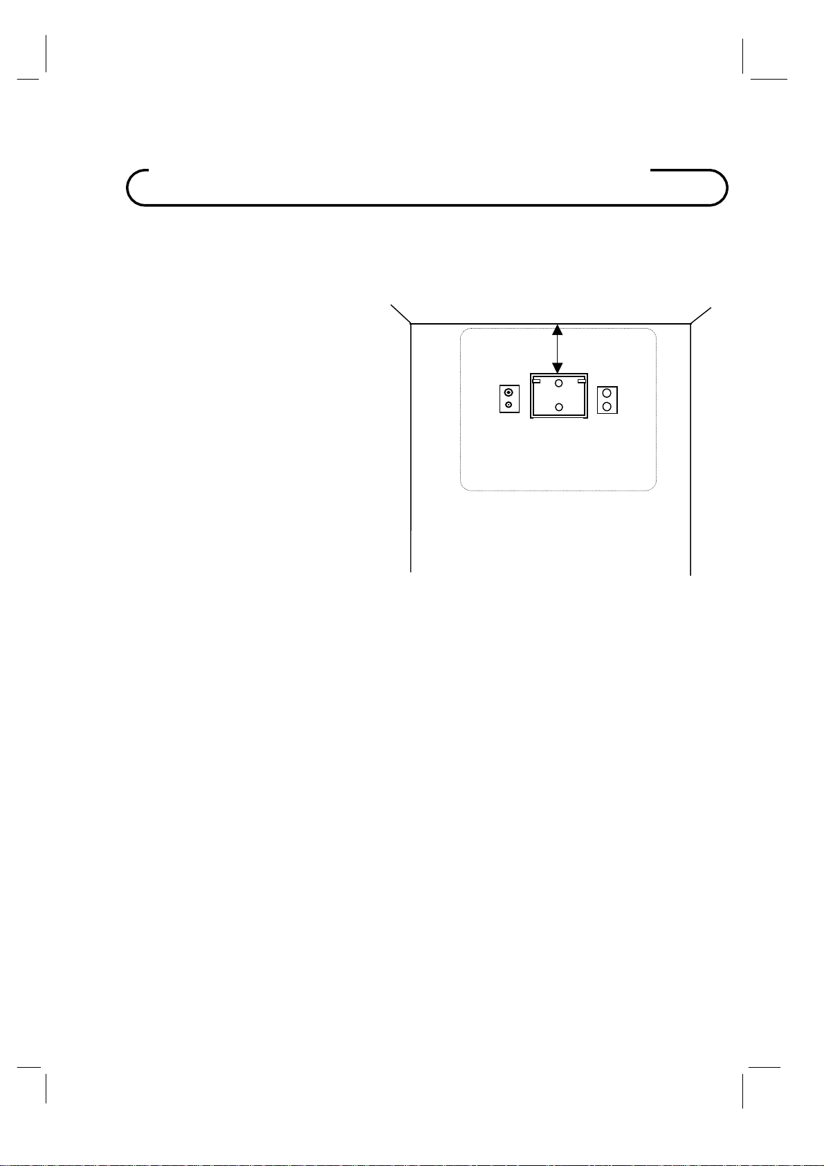
Wall Mounting on Wall Bracket
1. Refer to Figure 1. Select a location on the
wall approximately 9 inches below the
ceiling. Position the Wall Bracket and
locate two mounting holes. Secure the
bracket to the wall (mounting hardware is
not included).
NOTE: Do not locate AC, Across-Room
Wiring, and CATV Signal outlets below the
Wall Bracket’s location as it will cause
clearance issues and interfere with the
TV’s cabinet when mounted to the bracket.
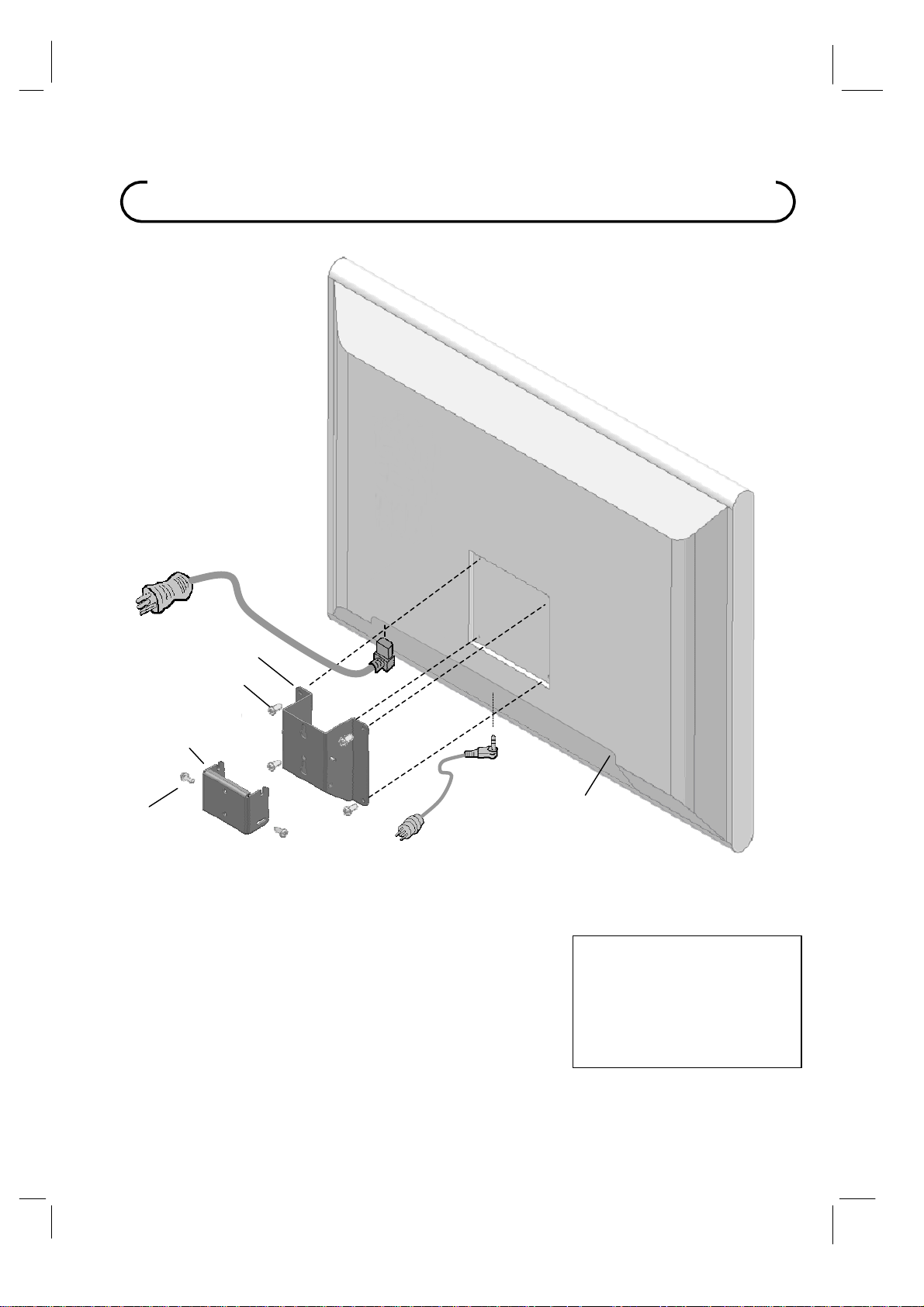
2. Refer to Figure 2. Position the Back Mount
on the LCD TV cabinet. Attach with four
M4 screws provided.
3. Mate the Back Mount to the Wall Bracket
making sure the pivot pins are retained in
the “U” shaped slot. Using the pilfer
security driver packed with the hardware,
secure with two 10x32 pilfer screws.
4. Connect the AC line cord, Pillow Speaker
Jumper Cable, and CATV Coax Cable.
5. The TV’s tilt can be adjusted by loosening
both Pilfer Screws, adjusting tilt, and then
tighten.
CROSS-ROOM
& CATV SIGNAL
WIRING
P20LCDC 20” Vert x 23” Horiz
9”
Wall Bracket
NOT TO SCALE
Figure 1
C
14 Document Number: PD196-103 Rev 1
Page 15
r
A
Wall Mounting on Su
pp
C Power Cord
lied Bracket
Pilfer Screws (2)
Wall
Mount
Back Mount
M4 x 6mm
Screws (4)
Pillow Speaker Jumpe
Figure 2
CATV Coax Connector
(Coax Not Shown)
Note: Make sure the pillow speaker
selection switch is set to the correct
setting before plugging in the jumper.
The switch changes the voltage
supplied to the pillow speaker, and
could overdrive the pillow speaker if
incorrectly set
15 Document Number: PD196-103 Rev 1
Page 16
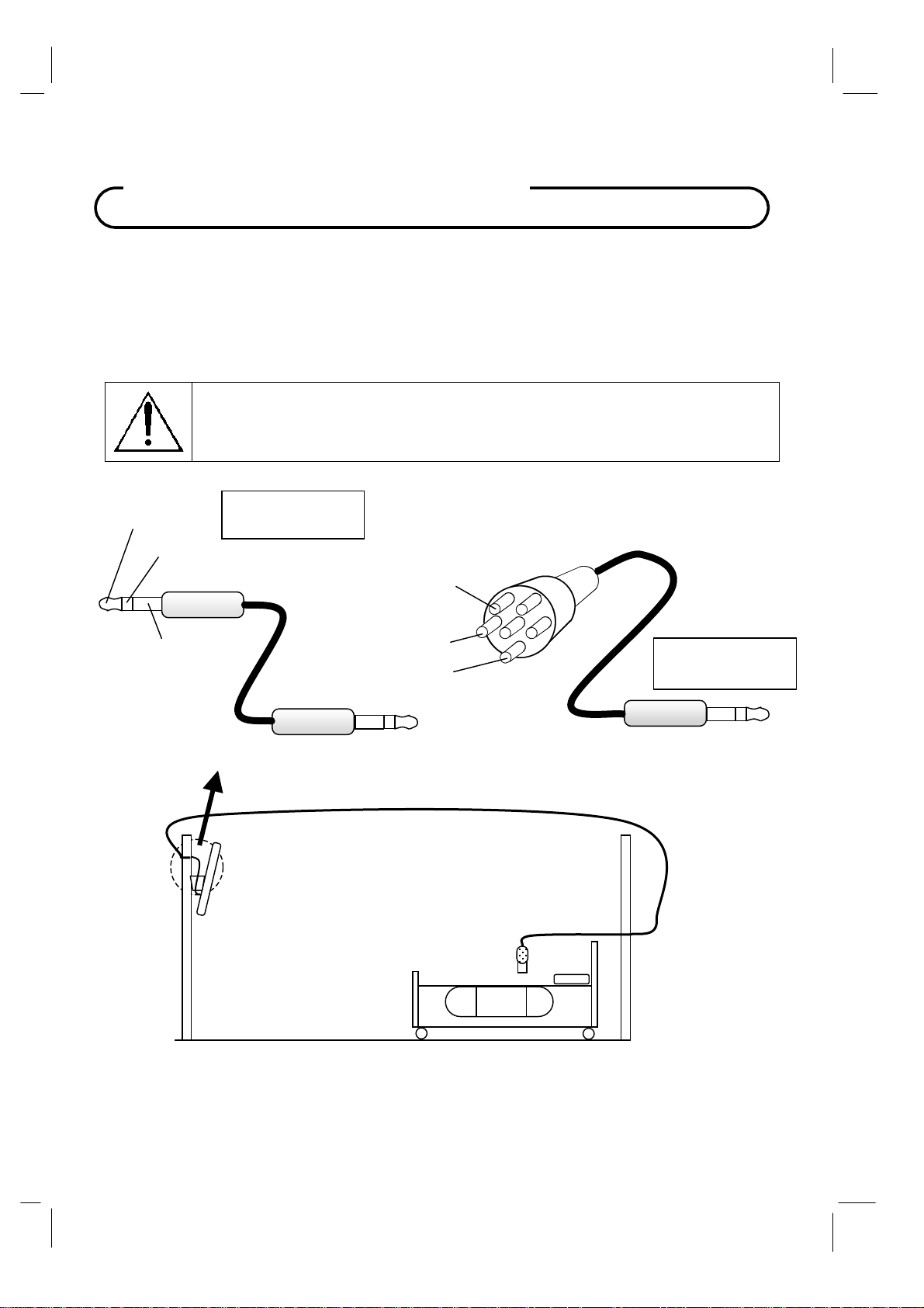
Across-Room Wiring
A ¼” stereo style pillow speaker (pendant control) jack is located on the TV’s connector panel on the
backside. This TV is designed to work with either a digital pillow speaker that generates digital style
control codes or a single-button analog (switch-style) pillow speaker. A rear panel mounted switch
allows use of different brands of pillow speakers and supports the major brands; Zenith, Philips, and
RCA pillow speakers. Please refer to the “Pillow Speaker” section elsewhere in this manual for
details.
WARNING: DO NOT connect the pillow speaker circuit Common to earth ground.
Grounding of the Common will defeat the isolation circuitry of the television and
possibly expose the patient to harmful shock currents should a wiring fault occur.
SPEAKER
DATA / SWITCH
COMMON
Optional Jumper
PD106-417
SPEAKER
COMMON
DATA / SWITCH
Jumper Supplied
with TV
16 Document Number: PD196-103 Rev 1
Page 17
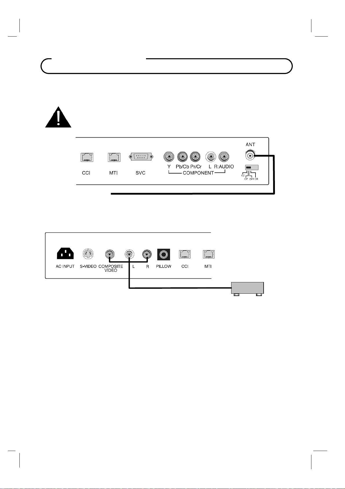
Connections
Antenna “ANT” Connection
CAUTION: Some hospital cable systems provide power voltage on the coaxial
cable. This TV is NOT designed to be powered via a coaxial cable. Do not
connect to a powered coaxial cable. Damage will result to the TV.
Hospital Coax Cable
COMPOSITE VIDEO/AUDIO IN
Connects composite video and stereo or mono audio from devices such as VCR’s,
DVD’s, and Game Boxes.
VCR
1. Connect the audio outputs from the device (L, R) to the L & R on the TV. Connections are
color code.
2. Connect the video output from the device to the COMPOSITE VIDEO jack on the TV.
Connection is color-coded.
3. Verify that the COMPOSITE VIDEO mode is enabled in the Source Setup menu. Please see
“Source Setup” instructions elsewhere in this manual for details.
4. Press the TV/AV button repeatedly until COMPOSITE VIDEO appears in the lower right corner
of the screen indicating selection of Composite Video.
5. Activate the device.
17 Document Number: PD196-103 Rev 1
Page 18
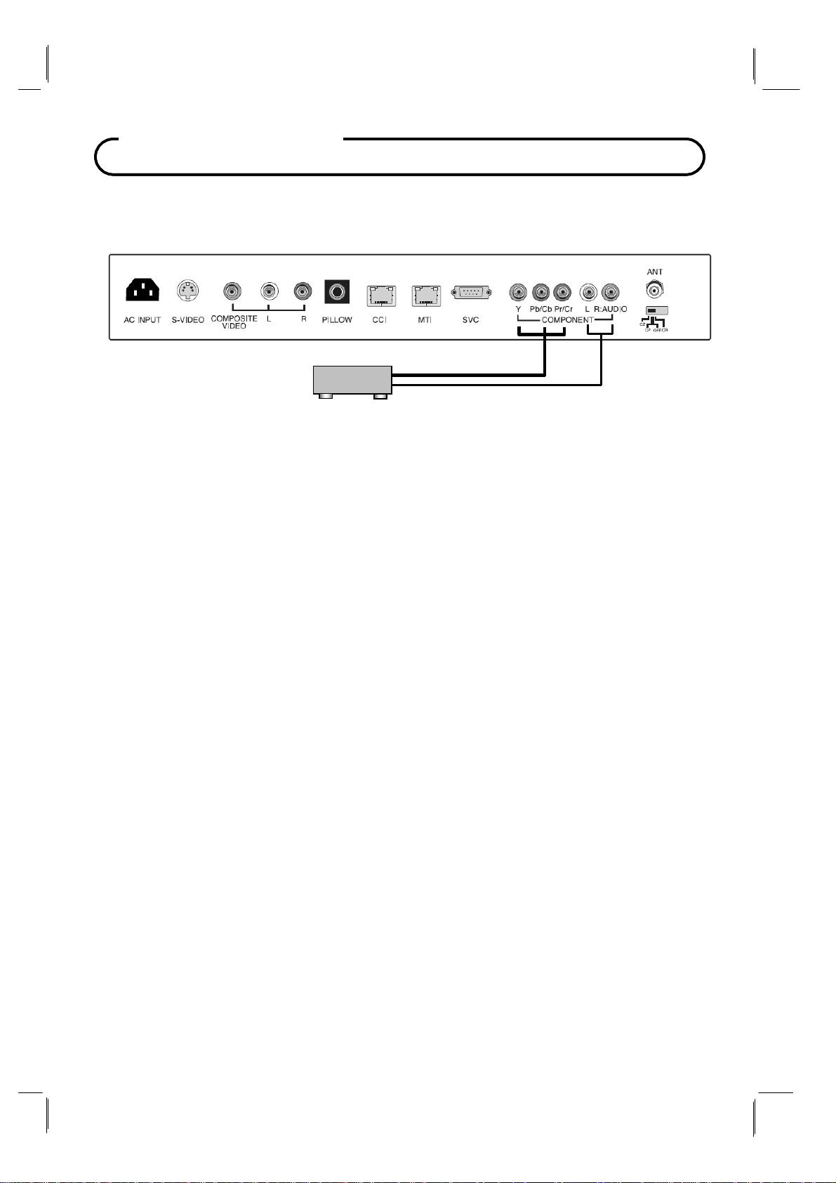
Connections
Component IN
The TV supports devices with component video signals such as a DVD.
DVD
1.
Use a component video cable to connect the DVD player’s Y/Pb/Pr jacks to the TV's
component Y/Pb(Cb)/Pr(Cr) jacks.
sometimes labeled
Use an audio cable to connect the DVD player’s Audio OUT jacks to the TV's Audio IN
2.
jacks. Be sure to use the appropriate audio inputs adjacent to the corresponding
Video input.
3. Verify that the appropriate Component source is enabled in the “Source Setup” menu.
Please see “Source Setup” instructions elsewhere in this manual for details.
4. Press the TV/AV button repeatedly until COMPONENT appears in the lower right corner
of the screen indicating selection of the component input.
Activate the DVD. The DVD playback picture appears on the screen.
5.
Y/Cb/Cr or Y/B-Y/R-Y. If so, connect the cables to like colors.
NOTE: The Y/Pb/Pr jacks on your DVD player are
18 Document Number: PD196-103 Rev 1
Page 19
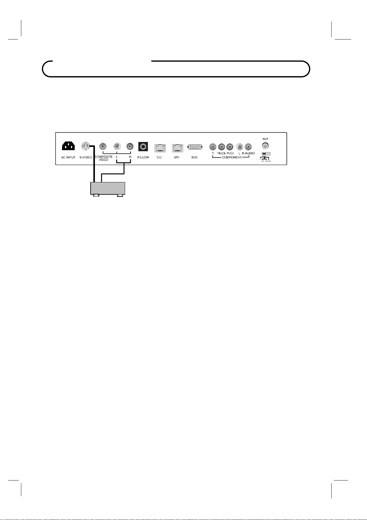
Connections
S-VIDEO Connection
If the external equipment you connect has an S-VIDEO jack, you can use an S-VIDEO cable
for improved picture quality (compared to an
1.
Connect the VCR’s S-Video output directly to the TV’s S-VIDEO connector.
2. Connect the VCR’s L & R audio to the TV’s L & R connector inputs.
3. Verify that the S-VIDEO mode is enabled in the Source Setup menu. Please see “Source
Setup” instructions elsewhere in this manual for details.
4. Press the TV/AV button repeatedly until S-VIDEO appears in the lower right corner of the
screen indicating selection of S-VIDEO.
Activate the VCR. The VCR playback picture appears on the screen.
5.
VCR
A / V cable).
19 Document Number: PD196-103 Rev 1
Page 20

Connections
Pillow Speaker
The pillow speaker (pendant control) jack is located on the TV’s connector panel. Control of
the TV using an externally wired pillow speaker is possible. Please see the “Installation”
section elsewhere in this manual for wiring details.
Pillow Speaker
1.
Select the appropriate brand of digital pillow speaker using the recess slide switch
next to the PILLOW jack.
CZ for Zenith
CP for Philips
CR for RCA
OFF to disable the pillow speaker
For analog style pillow speakers set the switch to either CZ, CP, or CR.
NOTE: The TV is shipped from the factory with the switch in the OFF position.
©
©
©
CAUTION: Confirm pillow speaker type and set the slide switch
appropriately BEFORE connection the pillow speaker to the TV.
Failure to follow this procedure could result in damage to the pillow
speaker and / or TV.
2.
Connect the pillow speaker to the PILLOW jack.
3. Operate the pillow speaker and verify correct control.
Zenith is a trademark of the Zenith Electronics Corporation, All Rights Reserved.
Philips is a trademark of Koninklijke Philips N.V. All rights Reserved.
RCA is a trademark of the RCA Corporation. All Rights Reserved.
20 Document Number: PD196-103 Rev 1
Page 21

Basic Operation
Turning the TV On and Off
1. Connect the AC power cord to the TV. A front mounted indicator light will illuminate Red
indicating the TV has power, but is currently off.
2.
Press the POWER button on the remote control, or the TV’s ON/OFF button, or the pillow
speaker’s TV power button. The TV’s indicator light will illuminate Green indicating the
TV is turned ON. The TV’s screen display requires approximately 3 seconds to warm
up and display a picture.
3.
Press the POWER button again to turn the TV off. A front mounted indicator light will
illuminate Red indicating the TV is off.
Channel Selection
You can select a channel number with the CH▲ / CH▼ or NUMBER buttons.
NOTE: Not all pillow speaker models support direct entry of channels.
Volume Adjustment
Press the VOL◄ / VOL► button to adjust the sound level.
NOTE: Some pillow speakers contain only a volume wheel that may also require adjustment.
Last Channel
Press the LAST button on the remote control to view the last program you were watching.
NOTE: Some pillow speakers do not support last channel viewing.
Sound Mute Function
Press the MUTE button. The sound is switched off and the mute display appears.
To cancel mute mode, press the MUTE button again,
NOTE: Some pillow speakers do not support the mute feature.
or press
VOL◄
or
VOL►.
Sleep Timer
The sleep timer turns the TV off after activation of a preset time limit.
Press the SLEEP button on the remote repeatedly to select the number of minutes. The time
limit can range from 10 up to 120 minutes in value.
21 Document Number: PD196-103 Rev 1
Page 22
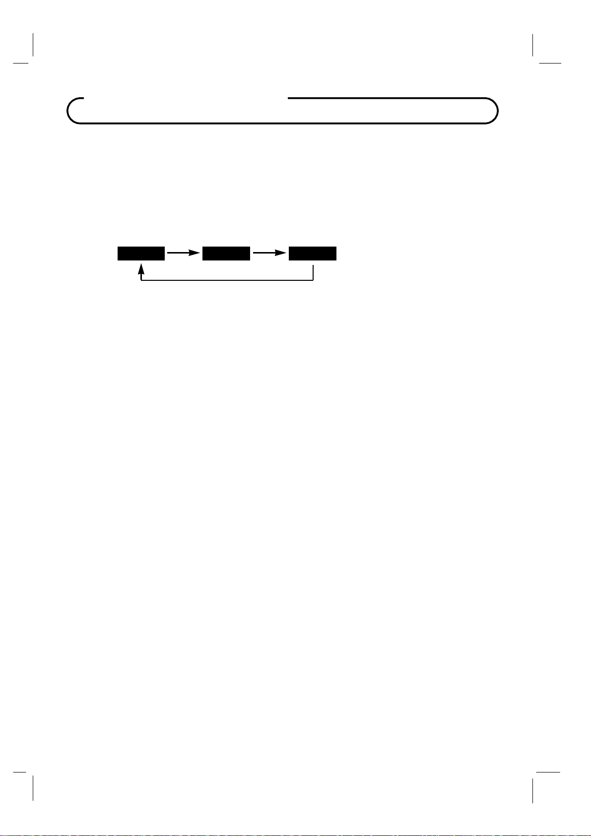
Basic Operation
On Screen Menu Language Selection
You can adjust the language used in displaying the (OSD) on screen display.
1.
Press the SETUP button on the remote control.
2.
Press the CH▲
3.
Press the
◄►
/ CH▼ button to select the OSD Language menu.
button to select your desired language.
English
4.
Press the SETUP button to exit the main menu.
Francais Espanol
Changing the Source Input
The TV can be switched to other display modes such as VCR, DVD, PC, or other externally
connected devices.
1.
Press the TV/AV button to change to another source input.
NOTE: The desired source input must be enabled in the Source Setup menu.
“Source Setup” instructions elsewhere in this manual for details.
2.
Alternatively, press CH▲ / CH▼ buttons until reaching the highest channel (or below to the
lowest channel). All activated sources will appear in the channel table above the highest
channel and is directly viewable.
NOTE: The “Channel to Other Sources” must be enabled in the FEATURES menu to allow
top of channel display of activated sources.
Please see
22 Document Number: PD196-103 Rev 1
Page 23
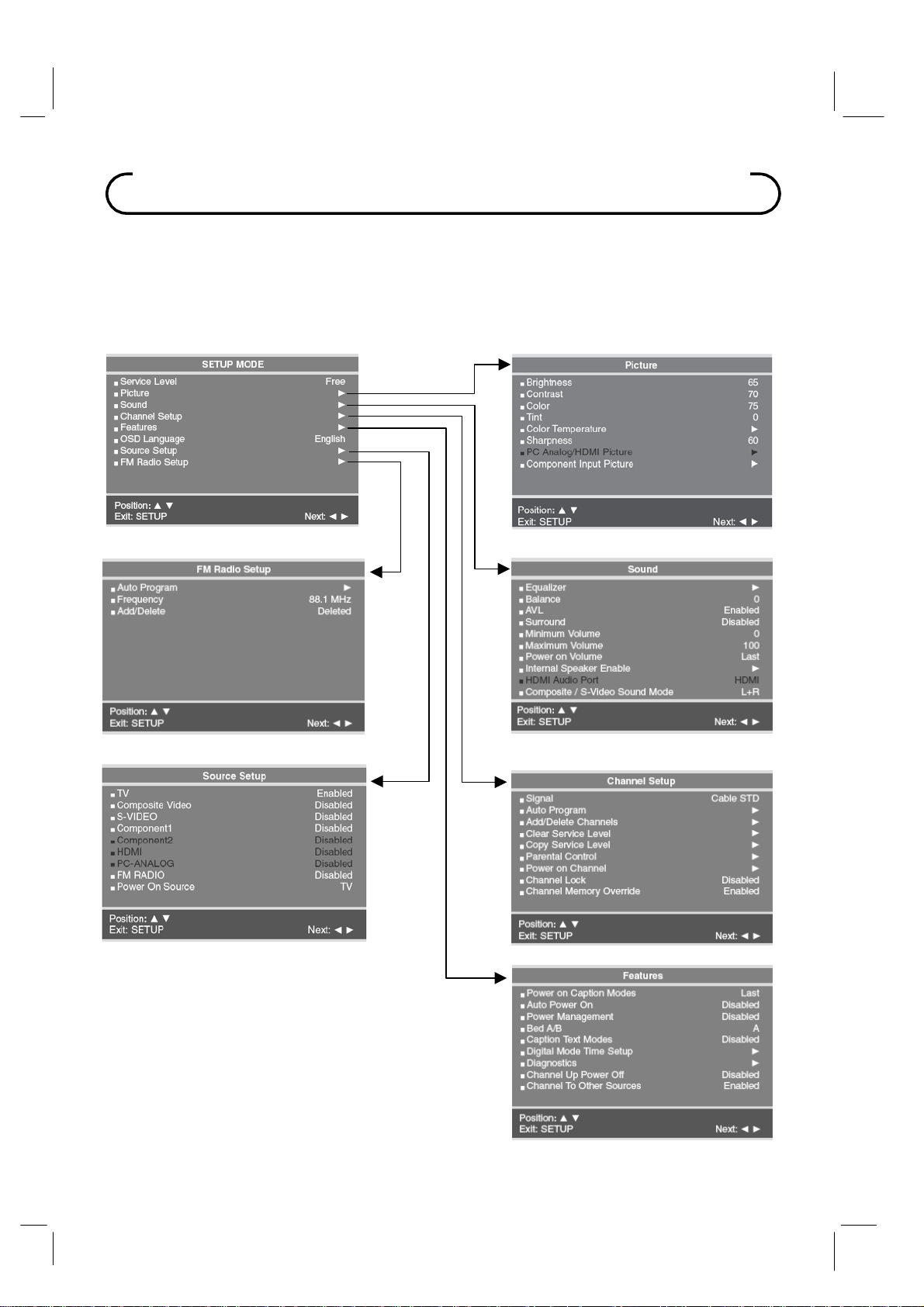
On Screen Menus and Displays
The TV is programmed using the Menus.
1. Press the SETUP button on the IR remote control to display the main SETUP menu.
2. Press the
3.
Adjust or enter the menu item using the
Press the SETUP button on the IR remote control to return to the preceding menu.
4.
CH▲ / CH▼ buttons to select a menu item.
VOL◄ / VOL► buttons.
23 Document Number: PD196-103 Rev 1
Page 24
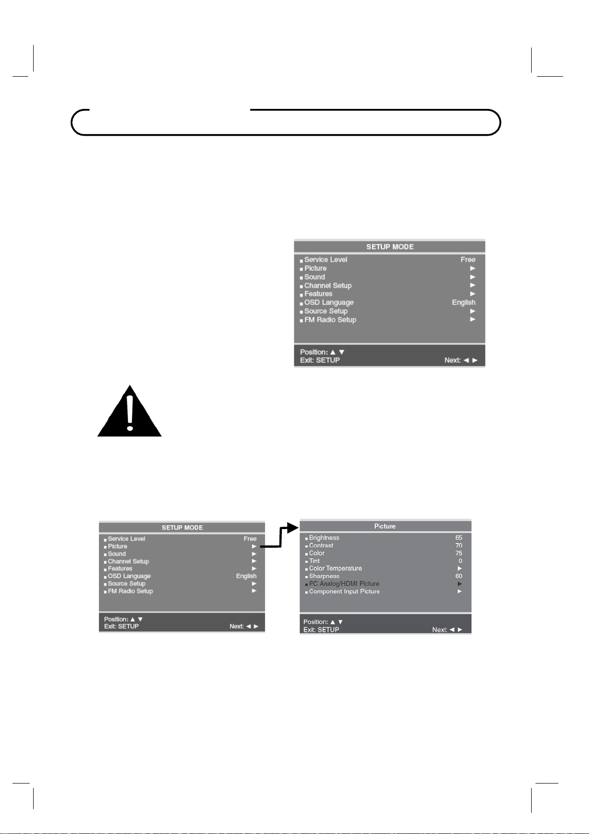
Service Level
A
A
Service Level
The TV can be configured with 3 different banks of channels called Service Levels. Each
Service Level can be programmed with any combination of channels. For example, a
hospital usually elects to dedicate one of the service levels for Pediatrics and another for
Maternity since additional or banned channels may be found in either location that would
not be normally shown to the general patient population. A DISABLED service level is also
available that does not display any channels but rather a disabled message on the TV’s
screen when the TV is turned on.
To change a Service Level.
1. Press the MENU button to display the
SETUP menu.
2. Press the
highlight the Service Level item.
3.
Press the VOL◄ / VOL► button to
select the desired service level.
4.
Press the MENU button or TV/AV
button to exit.
CH▲ / CH▼ buttons to
NOTE: If a service level is selected that is empty and has not been
programmed with channels, a warning message will be displayed on the
TV stating “No Channels Available, Please Contact a TV Representative.”
fter 15 seconds the TV will shut itself off to conserve power. To
eliminate this message switch the TV to a Service Level that has been
programmed with channels.
Picture
djustment of picture Brightness, Contrast, Color, Tint, Color Temperature and Sharpness is
available to customize the levels you prefer using the on-screen menus. Alternately, PDI factory
preset picture modes can be selected using the remote control.
1. Press the MENU button to display the SETUP menu.
2. Select the Picture menu item.
3. Press the
4.
Adjust the picture item using the
5.
Press the MENU button to store the picture values.
NOTE: A separate set of picture parameters are available for external devices such as
DVD’s (Component Input Picture).
CH▲ / CH▼ buttons to highlight the desired picture item.
VOL◄ / VOL► buttons to the desired level.
24 Document Number: PD196-103 Rev 1
Page 25
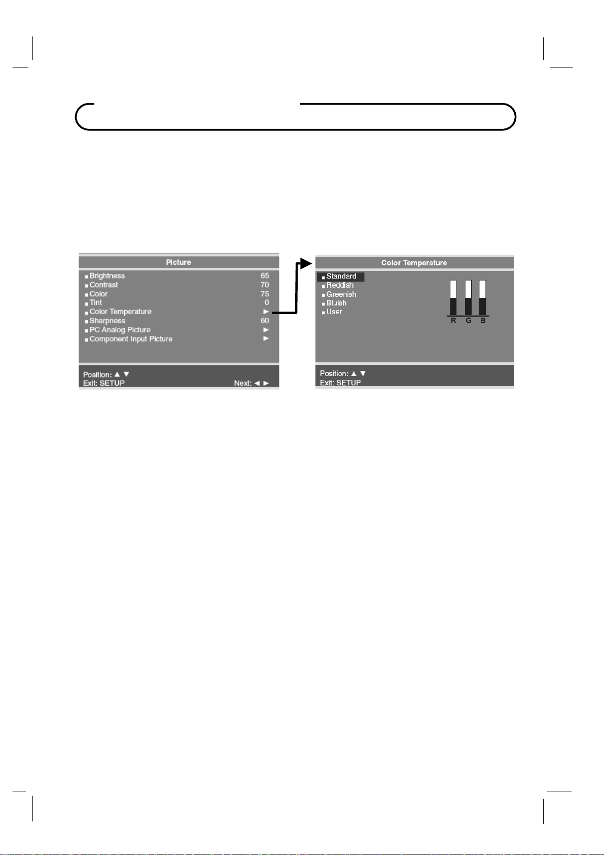
Picture Controls
Color Temperature
The color temperature menu appears only when the P20LCDC is in TV, Composite Video, or
S-Video modes. “Standard”, “Reddish”, “Greenish”, “Bluish” color temperatures are available
for selection, however the individual colors are not adjustable. The “USER” setting allows
individual adjustment of each of the TV’s primary colors. The color temperature setting is best
set using a calibrated signal source capable of generating a test signal containing both pure
white and pure black picture components.
25 Document Number: PD196-103 Rev 1
Page 26
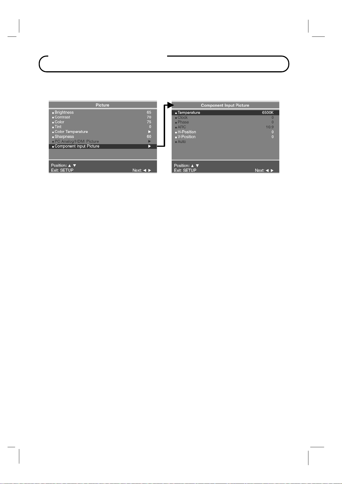
Picture Controls
Component Input Picture
When the TV’s source is set to Component Input additional picture adjustments are
available.
Temperature
Temperature is a measure of the warmth of an image. Two temperatures are available
6500K or 9300K.
H-Position (Horizontal Position)
The H-Position moves the picture left or right across the screen.
V-Position (Vertical Position)
The V-Position moves the picture up or down across the screen.
26 Document Number: PD196-103 Rev 1
Page 27
Sound Control
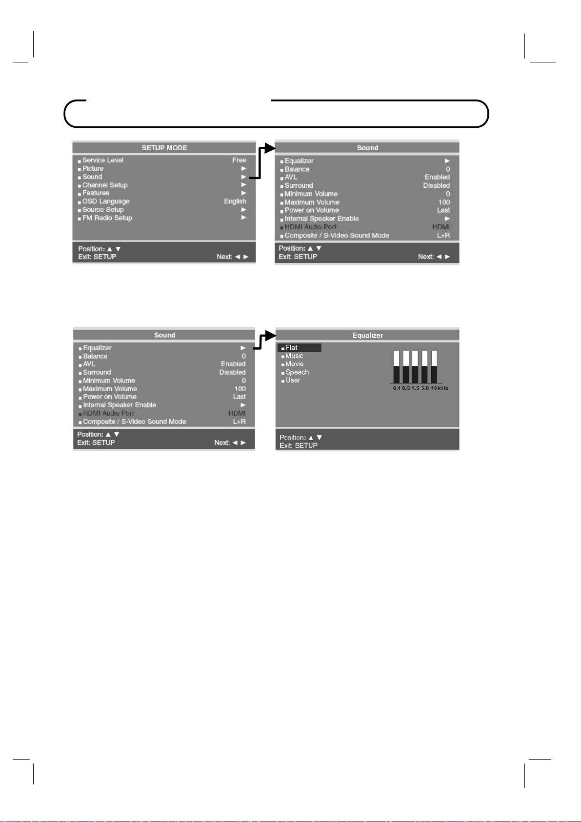
Sound
The Sound menu allows very precise adjustment of several sound parameters.
Equalizer
Four non-adjustable preset PDI factory sound modes are available: Flat, Music, Movie, or
Speech. An adjustable User mode allows custom adjustment of the sound’s tonal
frequency response.
1. Press the SETUP button on the remote.
2. Select the Sound menu item.
3. Press the CH▲ / CH▼ button and select Equalizer.
A listing of available frequency bands and current settings will be display.
The Flat, Music, Movie, and Speech settings are factory preset sound modes and
cannot be adjusted. Select User to adjust and customize the sound equalization.
4. Press the VOL◄ / VOL► button to select the desired sound band.
5. Press the CH▲ / CH▼ button to adjust the strength of sound for that particular sound
band. Press the VOL◄ / VOL► button to select another sound band and adjust the
strength with the CH▲ / CH▼ button.
6. Press the SETUP button to return to the preceding menu.
27 Document Number: PD196-103 Rev 1
Page 28
Sound Control
Sound Status Memory
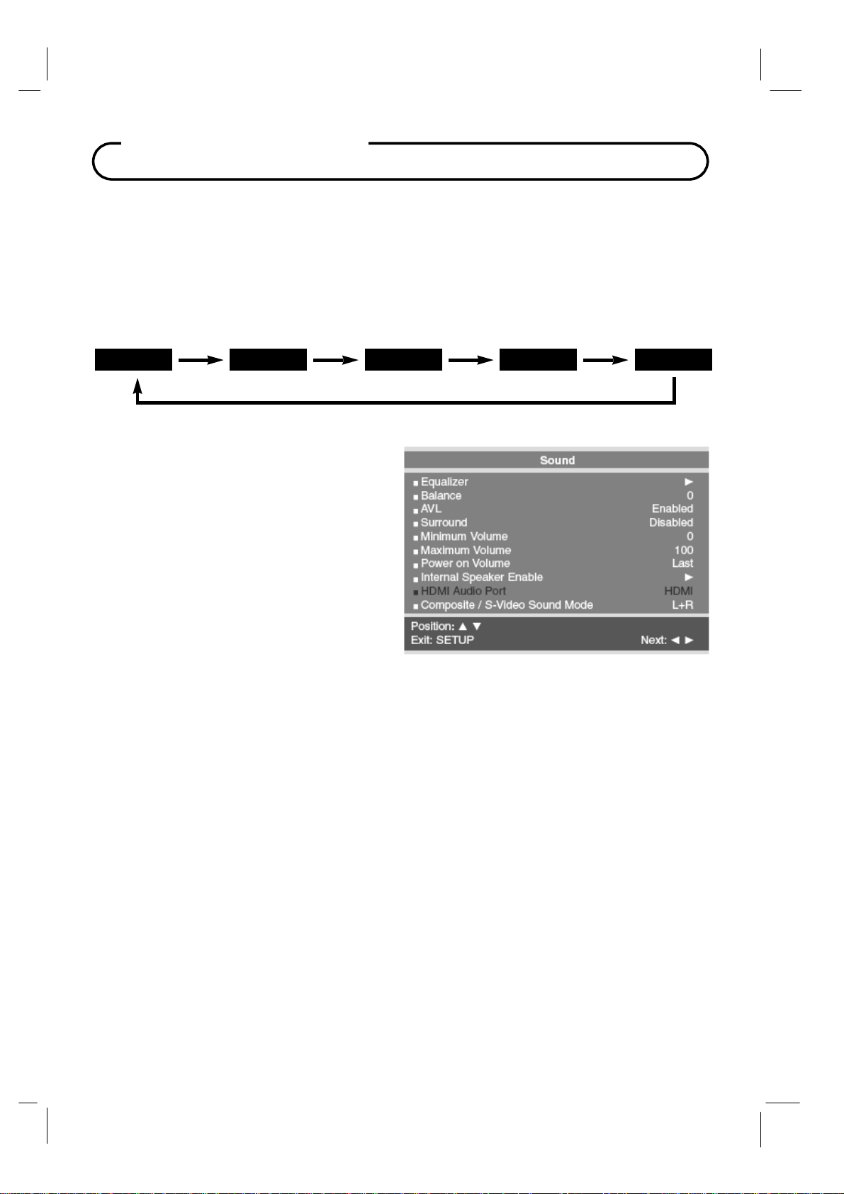
Selection of the factory preset equalized sound modes and user mode is also available directly
using the remote control.
1.
Press the SSM button on the remote control to display the current Sound Equalizer
setting.
Press the SSM button repeatedly to advance and select a different equalizer setting.
2.
Flat
Balance
Adjusts the sound balance from the left and
right speakers mounted in the
no effect on the pillow speaker.
1. In the
2.
3.
Sound menu, press the
button to select Balance.
Press
VOL◄ / VOL►
balance from the
Press the SETUP button to return to the
preceding menu.
Music
TV. Balance has
to adjust the sound
TV.
Movie Speech User
CH▲ / CH▼
AVL
Automatic Volume Level sound control is available through this setting. With the AVL set to
Enabled, the TV’s volume will be limited to two-thirds of maximum loudness. This feature
prevents sound blasting during commercials.
1. In
Sound menu, press the
Press
2.
3.
VOL◄ / VOL►
Press the SETUP button to return to theprecedingmenu.
CH▲ / CH▼
to select Disabled or Enabled.
button to select AVL.
Surround
Surround sound adds an extra dimension to the depth of to the sound.
1.
In Sound menu, press the
Press
2.
3.
VOL◄ / VOL►
Press the SETUP button to return to the preceding menu.
CH▲ / CH▼
to turn Surround Enabled or Disabled.
28 Document Number: PD196-103 Rev 1
button to select Surround.
Page 29
Sound Control
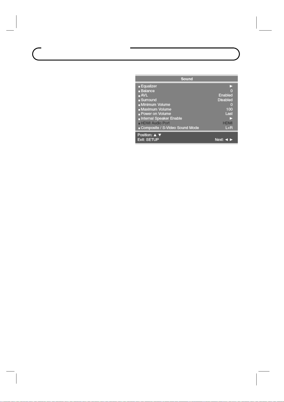
Minimum Volume
Sets the minimum volume level the TV
can reach. Setting this to any value other
than
0
guarantees that some level of
sound will always be heard when the
operating.
1.
2.
3.
In
the
Sound menu, press the
CH▼
button to select Minimum
Volume
Press the
select your preferred minimum volume
with the
Press the SETUP button to return to
the preceding menu.
.
VOL◄ / VOL►
TV turns on.
CH▲ /
button to
TV is
Maximum Volume
Sets the maximum volume level the TV can reach. This setting is useful for the hard-ofhearing patient who causes disturbance.
1. In
2.
3.
Sound menu, press the
Press the
Press the SETUP button to return to the preceding menu.
VOL◄ / VOL►
CH▲ / CH▼
button to determine your preferred maximum volume allowed.
button to select Maximum Volume.
Power On Volume
Sets the initial volume the TV starts at upon powering on. Once the TV is on, the volume can
be set to any allowable level.
1. In Sound menu, press the
2.
Press the
Setting the level to LAST
prior to turning off.
3.
Press the SETUP button to return to the preceding menu.
VOL◄ / VOL►
CH▲ / CH▼
button to determine your preferred volume when the TV turns on.
causes the TV to remember the last volume level used by the TV
button to select Power on Volume.
29 Document Number: PD196-103 Rev 1
Page 30
Sound Control
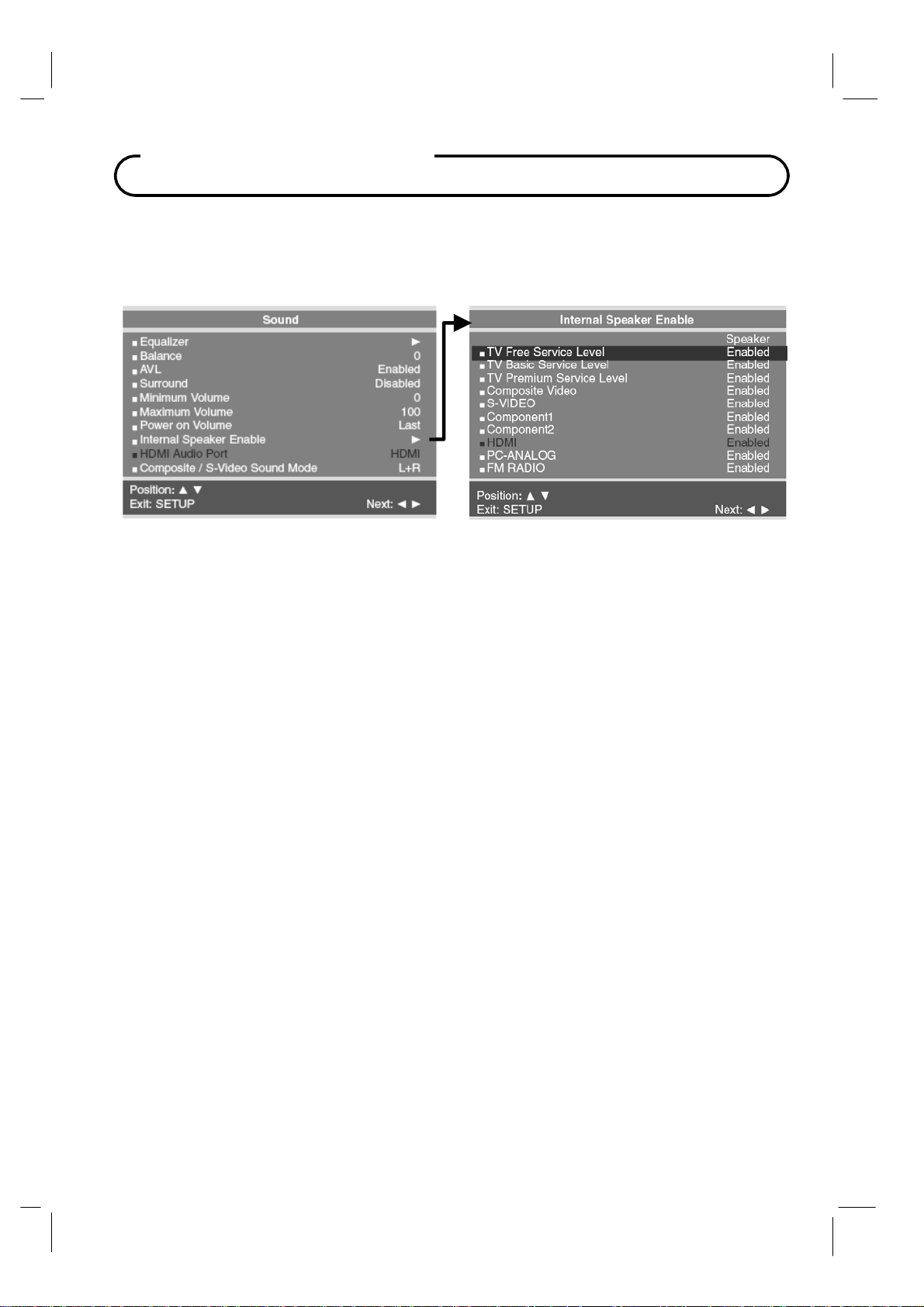
Internal Speaker Enable
The speaker’s inside the TV’s cabinet can be turned on or off for either different TV Service
Level or Source modes. Note: Sound to an attached pillow speaker remains on at all times.
1. In the Sound menu, press CH▲ / CH▼
menu item.
2.
Press the
3.
Press
4. Press the SETUP button to return to the preceding menu.
CH▲ / CH▼
VOL◄ / VOL► to select Disable or Enabled.
button to select the desired Service Level(s) or Sources.
button to select the Internal Speaker Enable
Composite / S-Video Sound Mode
The sound mode for the Component and S-Video sources can be set independently.
1. In Sound menu, press the CH▲ / CH▼ button to select Composite / S-Video Sound
Mode.
Press VOL◄ / VOL► to select L+R, L+L or R+R.
2.
L+R : Audio signal from audio L input is sent to left loudspeaker and audio signal from
audio R input is sent to right loudspeaker.
L+L : Audio signal from audio L input is sent to left and right loudspeakers.
R+R : Audio signal from audio R input is sent to left and right loudspeakers.
Press the SETUP button to return to the preceding menu.
3.
30 Document Number: PD196-103 Rev 1
Page 31
Channel Setup
Channel Setup
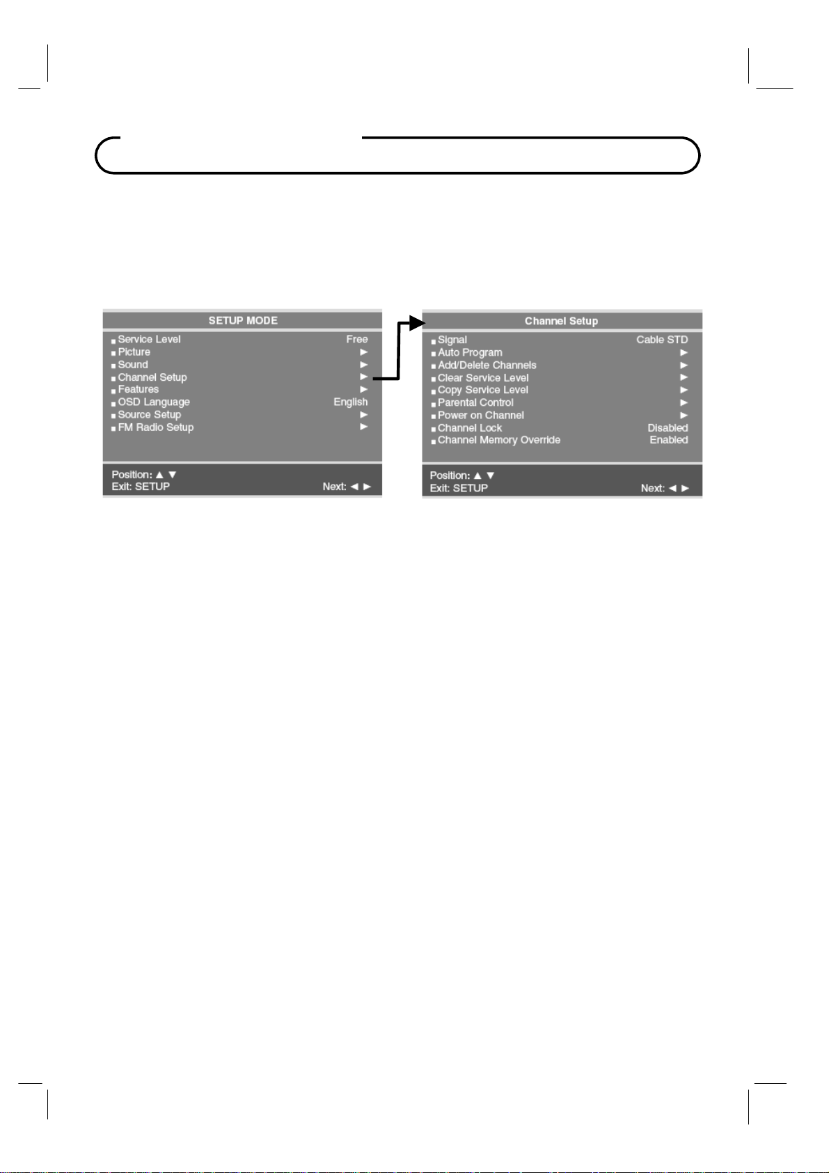
The TV offers three different programmable channel banks or Service Levels. A programming
remote control is required to perform all TV setup adjustments including programming
channels. The remote is NOT included with the TV and must be ordered separately – one
remote is capable of programming an entire hospital of televisions. Please order programming
remote control part number PD108-420.
Signal
Four different tuning types are available depending upon the healthcare facilities signal style.
Selection of the correct signal type is required for the TV to recognize all possible channels and
before any channel programming can begin.
1. Press the SETUP button to display the SETUP MODE menu.
2. Press the CH▲ / CH▼
3. Press VOL◄ / VOL►
hospitals use the Cable STD signal style.
button to select Signal.
to select Air, Cable STD, Cable IRC or Cable HRC. NOTE: Most
31 Document Number: PD196-103 Rev 1
Page 32
Channel Setup
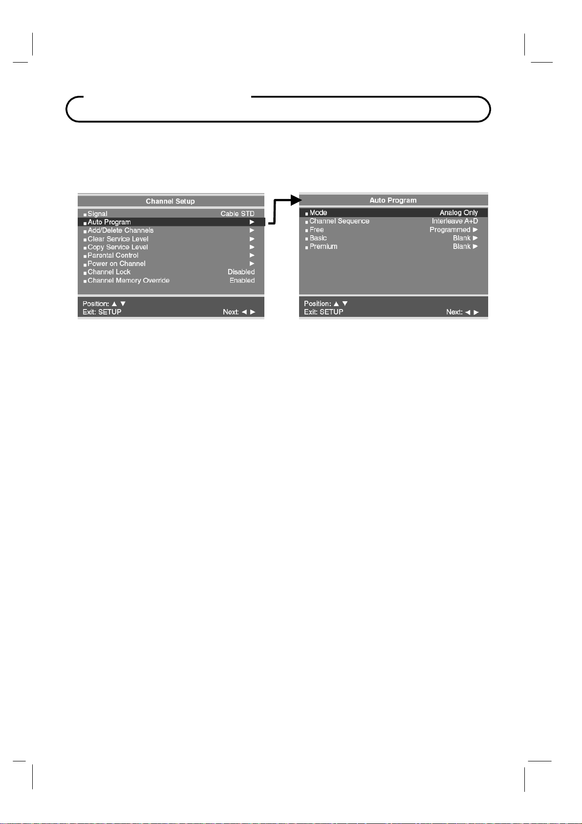
Auto Program
The TV automatically scans each available channel for activity. Channels that display
activity are memorized into the selected Service Level.
1. Press the SETUP button to display the SETUP MODE menu.
2. Press the CH▲ / CH▼
3. Press VOL◄ / VOL► to set the scope of channel scanning.
Digital Only: TV searched for digital channels only.
Analog and Digital: TV searches for both analog and digital channels.
4. Press the CH▲ / CH▼
5.
Press
VOL◄ / VOL►
searching.
Analog Only: Only Analog channels are searched.
Interleave A+D: In the order of channel number regardless of the system.
All A then D: Digital channels are displayed after all analog channels.
6.
Press the
displays the current programming status of each level as either Programmed or Blank.
NOTE: A Programmed service level can also be re-programmed if desired.
7.
Press the
8. A confirmation menu will appear before proceeding. Press either the CH▲ to start auto
programming. Press CH▼
available channels. Auto programming may require several minutes to complete.
9. Press the SETUP button to return to normal TV viewing.
CH▲ / CH▼
VOL►
button to select Mode.
button to select the Channel Sequence menu item.
to set the Channel Sequence in which the channels are displayed after
button to select the Service Level you wish to program. The menu
button
to start auto programming.
button to cancel the operation.
The TV will now search all
32 Document Number: PD196-103 Rev 1
Page 33
Channel Setup
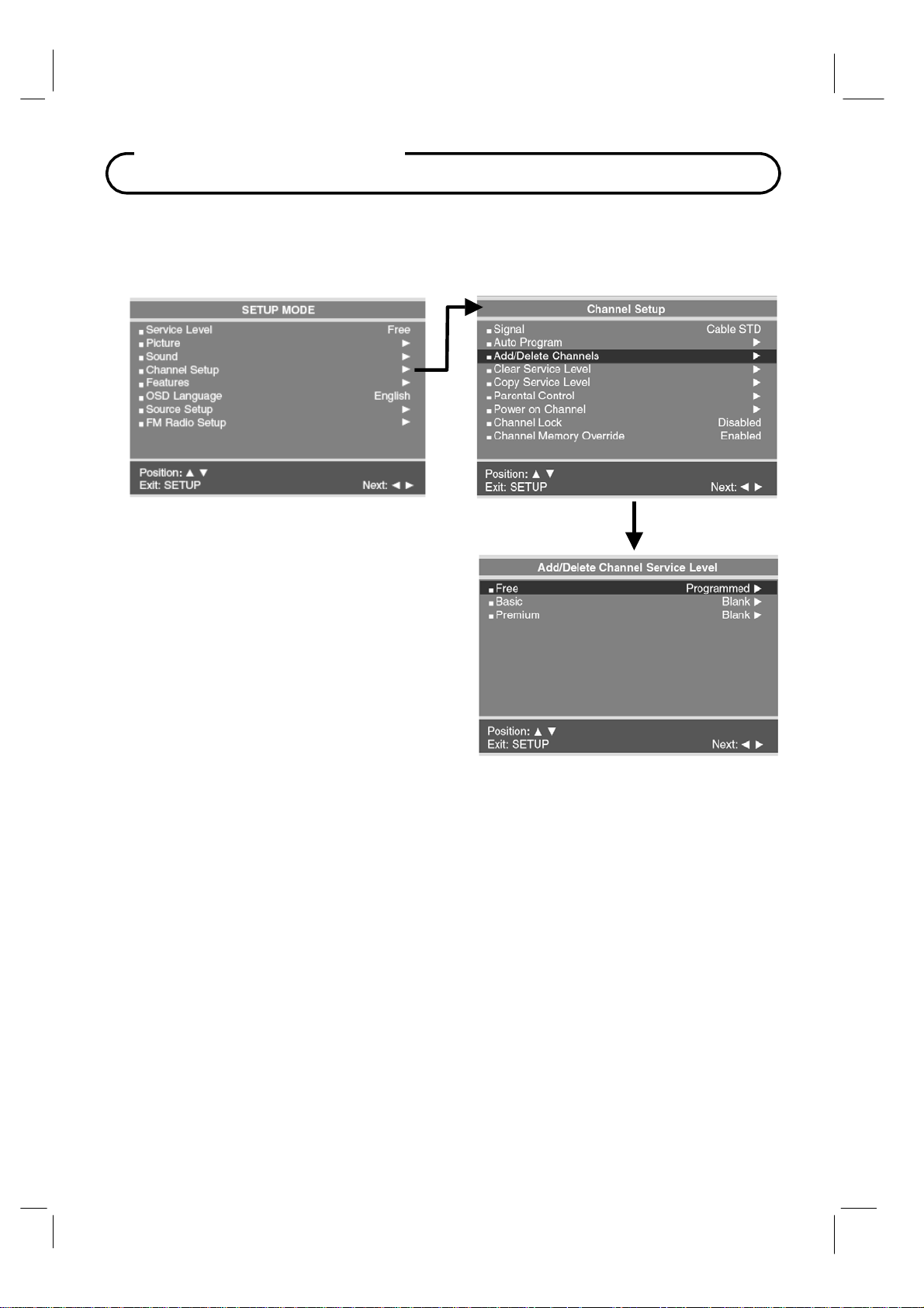
Add / Delete Channels
Individual analog TV channels that are missing can be added to a Service Level. Or, analog
TV channels that require deletion can be removed from a Service Level. Currently
registered Digital channels can be enabled or disabled in each service level.
1. Press the SETUP button to display the
SETUP MODE menu.
2. Press the CH▲ / CH▼
Channel Setup.
select.
3. Press the CH▲ / CH▼
Add/Delete Channels.
VOL► to select.
4. Press the CH▲ / CH▼ button to select the
Service Level you wish to add or delete
channels.
5. Press VOL◄ / VOL► to enter the
Add/Delete Channels menu for that Service
Level.
Press VOL◄ / VOL► to
button to select
button to select
Press VOL◄ /
33 Document Number: PD196-103 Rev 1
Page 34
Channel Setup
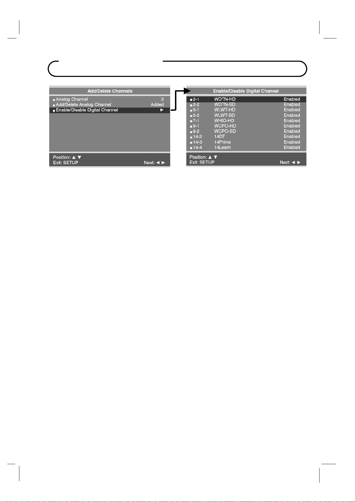
The Add/Delete Channels menu provides access to both Analog and Digital Channels.
6. Press VOL◄ / VOL► button to select the Analog Channel number. Then press the CH▲
/ CH▼ buttons to select Add/Delete Analog Channel. Use the VOL◄ / VOL► button to
select Added or Deleted.
7. Press CH▲ / CH▼ buttons to select Enabled/Disabled Digital Channels menu. Then
press the VOL◄ / VOL► button to enter. A status listing of the current memorized
channels is shown.
8. Select the channel to be changed using the CH▲ / CH▼ buttons. Use the VOL◄ / VOL►
button to change the status to Enabled or Disabled.
9. Press the SETUP button to return to the preceding menu.
34 Document Number: PD196-103 Rev 1
Page 35
Channel Setup
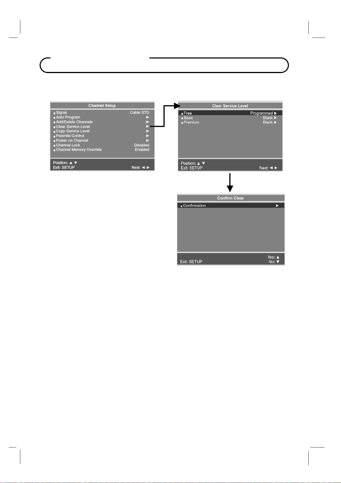
Clear Service Level
Empties a service level of all programmed channels leaving it blank.
1. From the Channel Setup menu, press
the CH▲ / CH▼ buttons to select
Clear Service Level menu.
2. A listing of service levels are shown
with the current programmed status.
Press the CH▲ / CH▼ button to select
the desired Service Level.
3. Press the VOL◄ / VOL► button once.
A Confirm Clear menu appears.
4. Press the CH▲ to confirm clearing of
the selected Service Level. Press the
CH▼ button to exit without making any
changes to the selected Service Level.
5. Press the SETUP button to return to
the preceding menu.
35 Document Number: PD196-103 Rev 1
Page 36

Channel Setup
Copy Service Level
Copies one service level of another.
1. From the Channel Setup menu, press the
CH▲ / CH▼ buttons to select Copy
Service Level menu. A Copy Service
Level menu appears and shows a source
(From) and destination (To) Service
Level.
2. Press the CH▲ button to adjust the From
Service Level.
3. Press the Press the CH▼ button to select
the To Service Level.
4. Press the VOL◄ / VOL► button once. A
Confirm Copy menu appears.
5. Press the CH▲ to confirm clearing of the
selected Service Level. Press the CH▼
button to exit without making any
changes to the selected Service Level.
6. Press the SETUP button to return to the
preceding menu.
36 Document Number: PD196-103 Rev 1
Page 37
Channel Setup
Parental Control
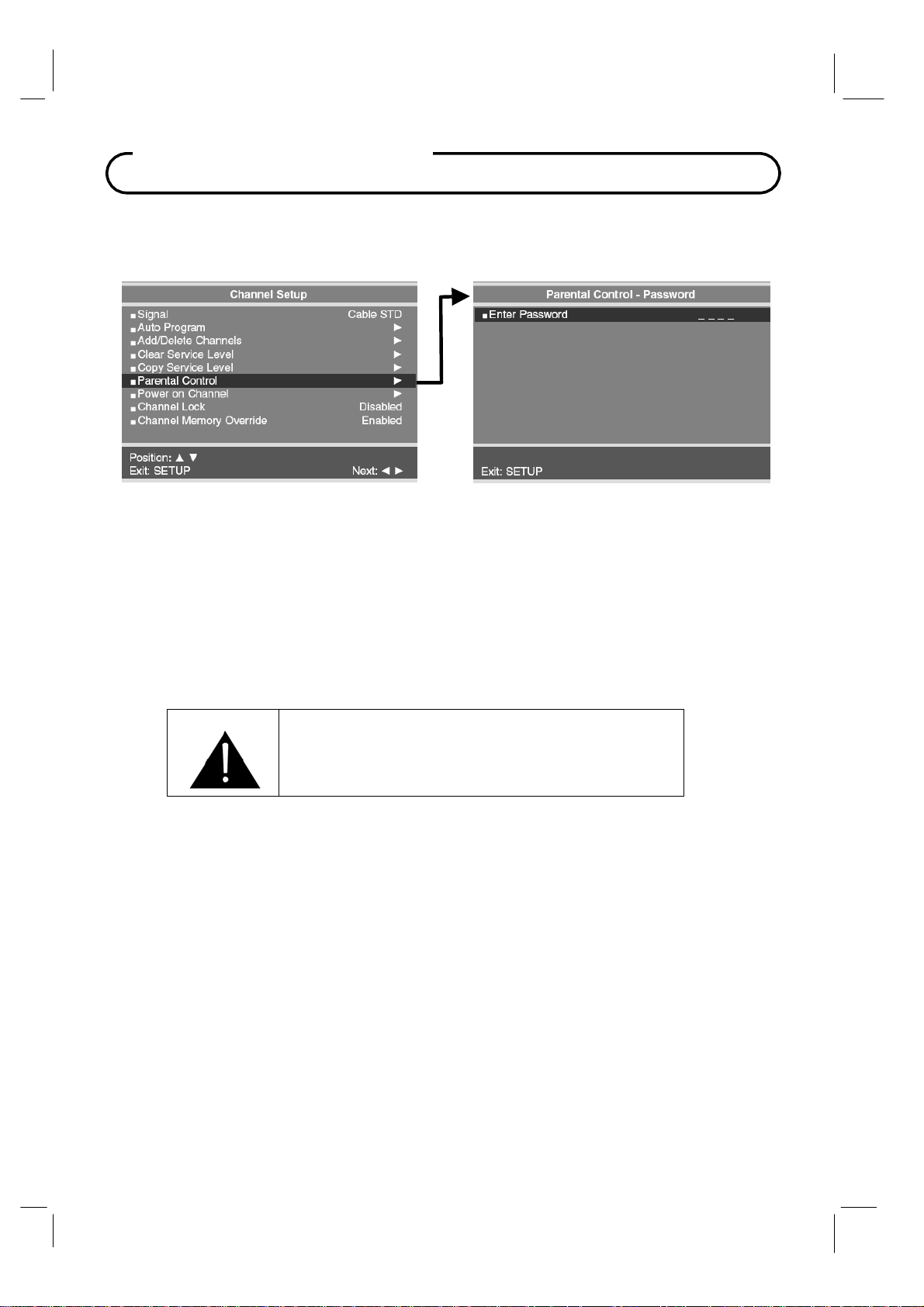
A parental control feature is available to restrict and block undesirable programs from appearing
on the
TV. This feature is of particular importance for televisions installed in pediatric wards.
If the Parental Lock is Disabled in Parental Control menu, an Enter Password screen will appear.
The default setting is Disabled.
1. In Channel Setup menu, press the
2.
Using an IR remote control, enter the four digit password. An "X" will be echoed as each
number is entered.
password is entered, return to
3.
You may exit at any time by pressing the SETUP button to return to the preceding menu.
The default input password for a new TV set is "
CH▲ / CH▼
the
Channel Setup menu and try again.
buttons to select Parental Control menu.
0000".
If the wrong
IMPORTANT: If the password is forgotten, it can
be reset to “0000” by pressing the front panel “CC”
button and the programmer remote “Setup” button
simultaneously and holding both for 5 seconds.
37 Document Number: PD196-103 Rev 1
Page 38
Parental Control
TV Rating
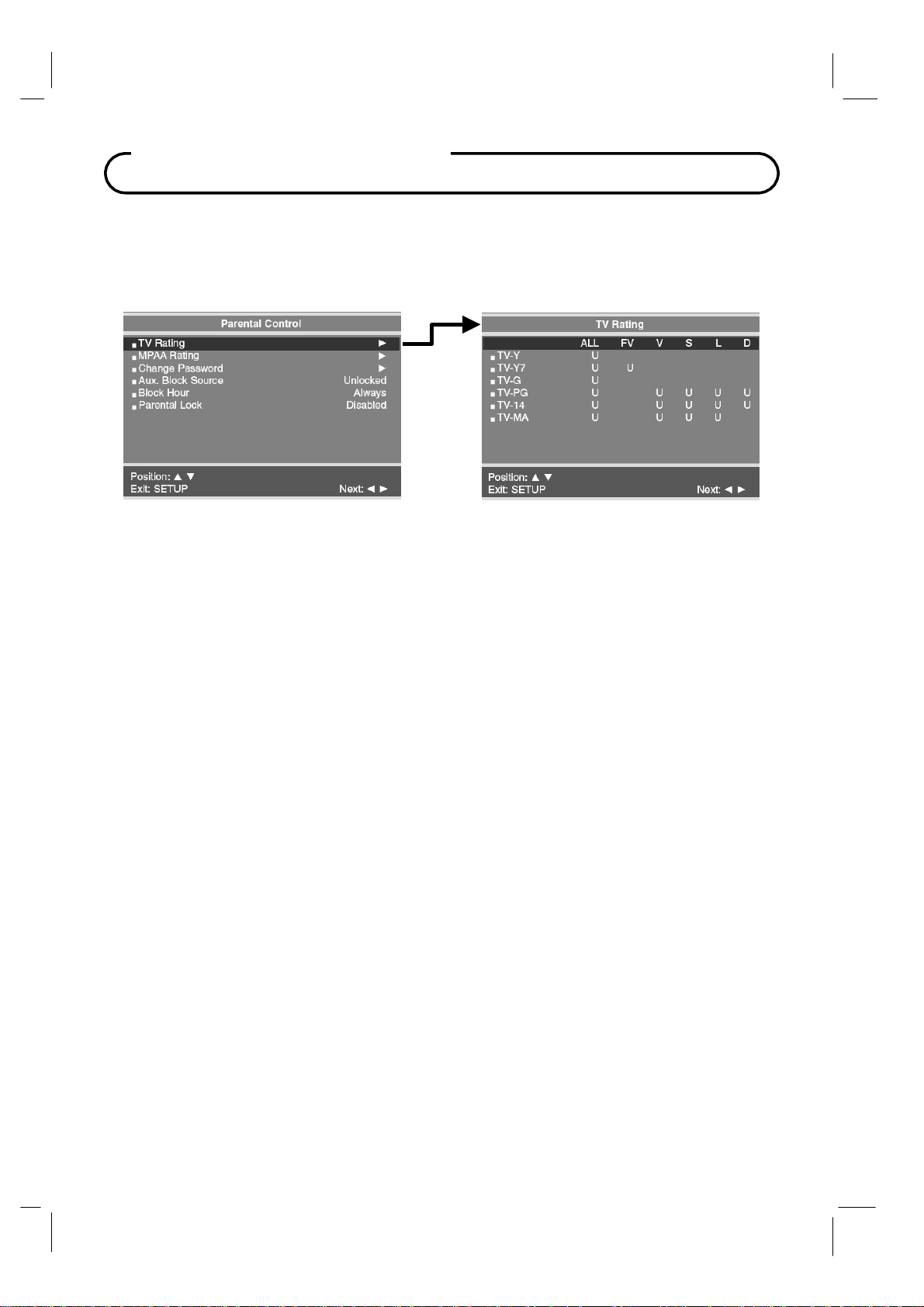
Most television programming are now rated. TV Rating allows the TV to selectively present
only programming content that is unblocked per its preset level.
displays a black screen only.
1.
In the Parental Control menu, press the
Then press the
Press the
2.
one of the
be highlighted. (U=Unblocked, B=Blocked).
While the "U" or "B' is highlighted, press the
3.
category.
Select one of these TV-Ratings: TV-Y, TV-Y7, TV-G, TV-PG, TV-14 or TV-MA
4.
the
TV-Rating is selected, repeatedly press the
through the available sub-ratings (ALL, FV, V, S, L
be displayed for each sub-rating. While the
CH▼
button to change the sub-rating. To select a different TV-Rating, press the
CH▼
buttons with cursor in the first column.
Press the SETUP button to return to the preceding menu.
5.
VOL◄ / VOL► button to enter.
CH▲ / CH▼
TV-Ratings is selected. Depending on your existing setup, a letter "U" or "B" will
CH▲ / CH▼
button to move to one of the six age-based categories. At this point,
CH▲ / CH▼
VOL◄ / VOL►
or D). A highlighted letter ("U" or "B") will
"U" or "B"
A
program that is blocked,
button to select the TV Rating menu.
buttons to block or unblock the
.
Then while
buttons. This will cycle
is highlighted, press the
CH▲ /
CH▲ /
38 Document Number: PD196-103 Rev 1
Page 39
Parental Control
MPAA Rating
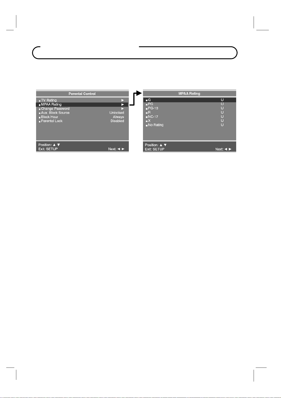
Most televised movies are now rated. MPAA Rating selectively allows the TV to only present
movie content that is unblocked per its preset level.
1. I
n Parental Control menu, press the
then press the
2.
Press the
3.
While a particular category is selected, press the
highlighted letter (‘U’ or ‘B’) will be displayed. Press the
the
‘U’ or ‘B’.
4.
Press the SETUP button to return to the previous menu.
NOTE: Parental Control
For example, if you block the "PG-13" category, then "R", "NC-17" and "X" will automatically be
blocked also.
VOL◄ / VOL►
CH▲ / CH▼
The TV displays a black screen for a blocked movie.
button to select a particular MPAA Rating.
will automatically block any category that is "more restrictive"
CH▲ / CH▼
button to enter.
button to select the MPAA Rating menu. And
VOL◄ / VOL►
CH▲ / CH▼
buttons to active it. A
button to change
39 Document Number: PD196-103 Rev 1
Page 40
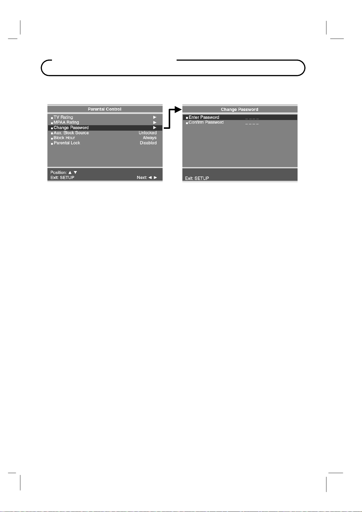
Parental Control
Change Password
The Parental Control access password can be changed using this menu.
1.
From the Parental Control menu, press the
Password. Then press the
Enter a new Password. Confirm the Password a second time by entering the same digits.
2.
3. Press SETUP to return to the previous menu.
VOL◄ / VOL►
CH▲ / CH▼
button to enter.
button to select the Change
Aux. Block Source
In addition to blocking the TV’s programming, the auxiliary sources can be blocked. When the
TV encounters a external signal source that is not appropriate per its settings, a black screen
appears with muted sound.
1. From the Parental Control menu, press the CH▲ / CH▼
source. Then press the
Press the buttons to change the “Unblocked” or “Blocked” status.
2.
3.
Press the SETUP button to return to the previous menu.
VOL◄ / VOL►
button to enter.
button to select AUX. Block
Block Hour
Block Hours sets the amount of time in hours you want Parental Control Active.
Parental Lock
With Parental Lock On, the Parental Function is active. Turn off to disable Parental Control.
40 Document Number: PD196-103 Rev 1
Page 41
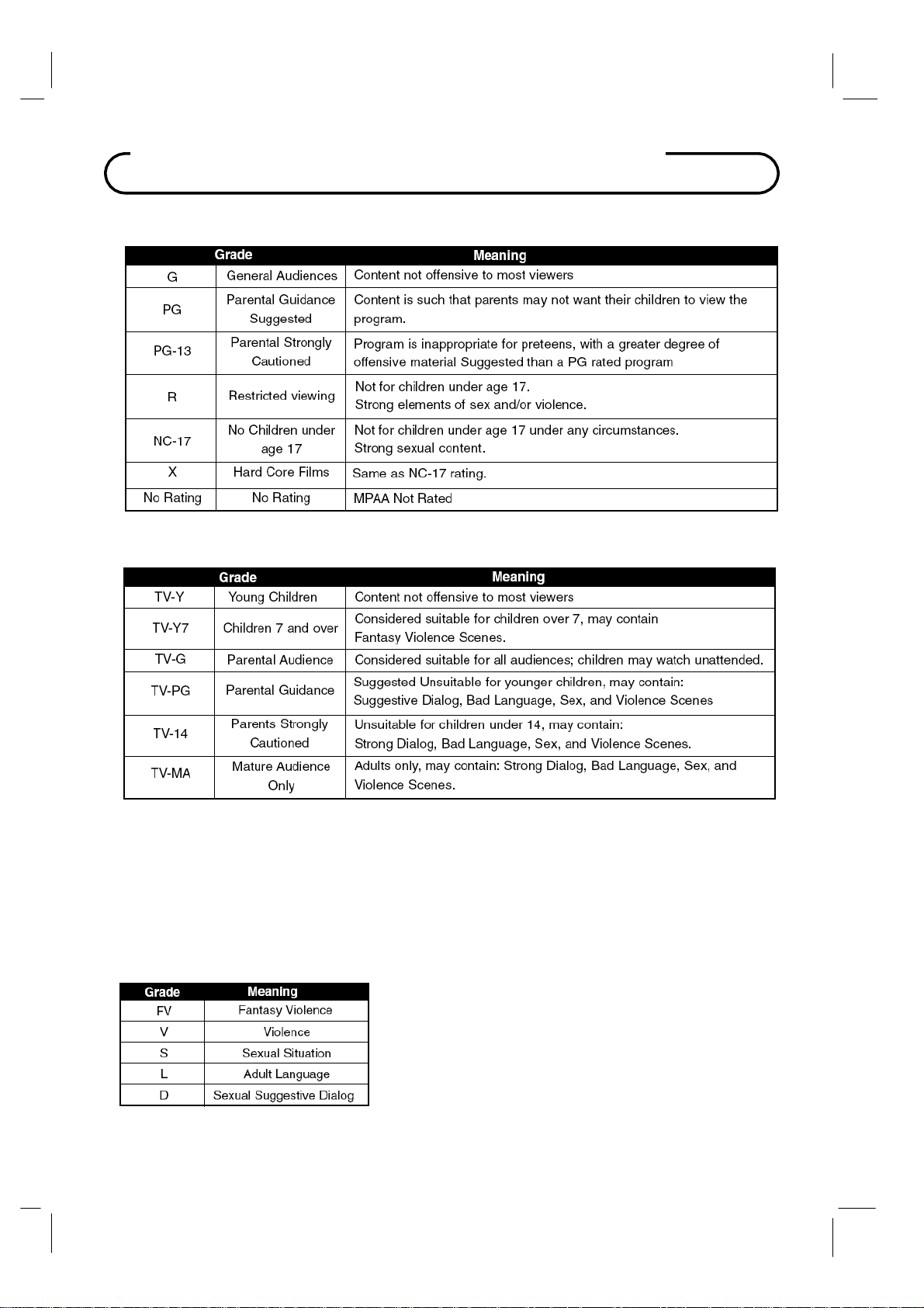
Movie & TV Rating Systems
MOTION PICTURE ASSOCIATION OF USA (MPAA) RATING SYSTEM
TV PARENTAL GUIDELINE RATING SYSTEM
NOTE
The V-Chip will automatically block certain categories that are ‘more restrictive’. If
you block
block
(TV-G, TV-PG, TV-14 and TV-MA).
The sub-rating of TV rating
TV-Y category, then TV-Y7 will be automatically blocked. Similarly, if you
TV-G category, then all the categories in the ‘young adult’ will be blocked;
41 Document Number: PD196-103 Rev 1
Page 42
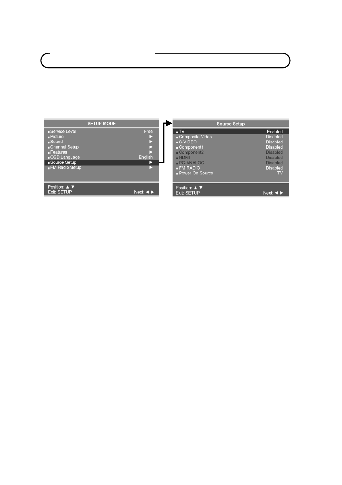
Source Setup
Enabling / Disabling Sources
The TV’s signal sources can be individually Enabled or Disabled. A TV that is switched to a
non-connected source generates nuisance hospital maintenance calls of “TV Not Working”,
when in fact the TV does work, but has been set to an inactive source. Please Disable all
of the TV’s sources that are not to be used.
1. From the SETUP menu press the CH▲ / CH▼
press the
2. Press the CH▲ / CH▼ buttons to select a source.
3. Press the VOL◄ / VOL► button to change the source status to either Disabled or
Enabled as desired. NOTE: Sources that are grayed out are not installed in the TV.
4. Press the SETUP button to exit.
VOL◄ / VOL►
button to enter.
button to select Source Setup.
Then
Power On Source
The TV can be preset to power on to a select source.
1. From the SETUP menu press the CH▲ / CH▼
press the
2. Press the CH▲ / CH▼ buttons to select Power Con Source.
3. Press the VOL◄ / VOL► button to change the source. NOTE: The source must be
enabled before it can be chosen as a power on source. The “LAST” entry causes the TV
to power on from the “LAST” source selected.
4. Press the SETUP button to exit.
VOL◄ / VOL►
button to enter.
button to select Source Setup.
Then
42 Document Number: PD196-103 Rev 1
Page 43
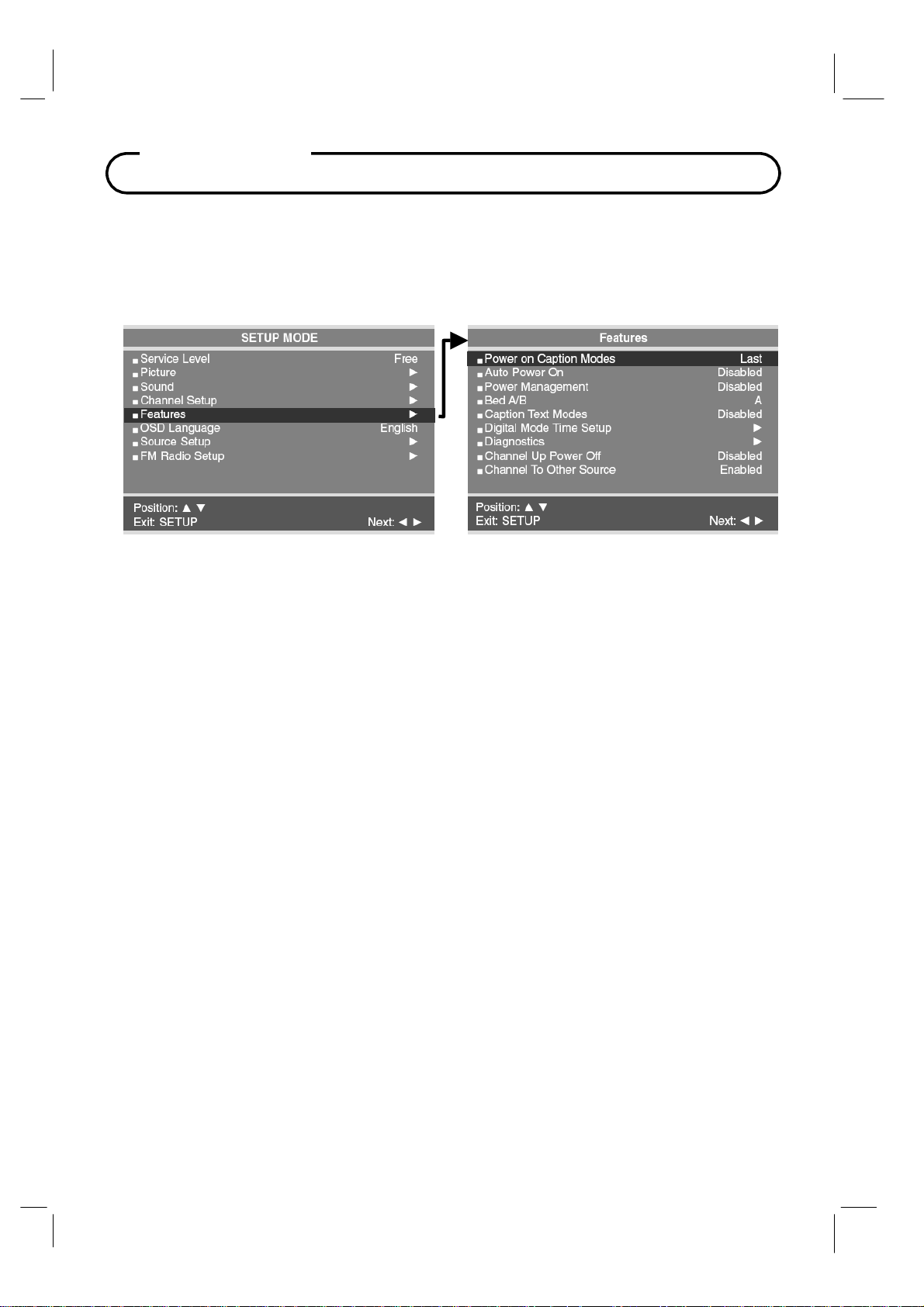
Features
The Features menu provides adjustable settings that customize the TV to your hospital.
Power On Captions Mode
Power on Captions Mode memorizes the caption setting upon powering the TV off. With this
feature set Off, the
With this feature set to Last, the TV powers on with the last caption’s setting.
1. Press the SETUP button.
2. Press the
3. Press the
4.
Press the
Press the SETUP button to return to the preceding menu.
5.
TV will always power on with captions disabled.
CH▲ / CH▼
CH▲ / CH▼
VOL◄ / VOL►
button to select the Features menu.
button to select Power On Captions Mode.
button to select Last or Off.
Auto Power On
The TV will turn on and stay on whenever electrical power is applied to the set. This feature is
useful for controlling the TV from a wall switch or preventing the TV from being turned off via the
front TV power button, IR remote, or pillow speaker.
1.
In Features menu, press the
Press the
2.
3.
Press the SETUP button to return to the preceding menu.
VOL◄ / VOL►
43 Document Number: PD196-103 Rev 1
CH▲ / CH▼
button to select Disabled or Enabled.
button to select Auto Power On.
Page 44

Features
Power Management
The TV will automatically power off after a specific period
of viewer inactivity providing energy savings.
In Features menu, press the
1.
select
Power Management.
2.
Press the
time. Set to Disabled to disable this feature.
3.
Press the SETUP button to return to the preceding
menu.
NOTE: Auto Power On must be set to Disabled for this
function to operate.
VOL◄ / VOL►
CH▲ / CH▼
button to determine active
Bed A/B
The TV can be controlled using a patient IR remote controls part number PD108-421. This
feature setting selects which IR remote control to recognize – bed A remote or bed B
remote.
1.
2.
3.
In Features menu, press the
Press the
Press the SETUP button to return to the preceding menu.
VOL◄ / VOL►
CH▲ / CH▼
button to select remote control A or B
button to
button to select Bed A/B.
.
Caption Text Modes
The captions is a process which converts the audio portion of a television program into written
words which then appear on the television screen in a form similar to subtitles.
1. In
2.
3.
Features menu, press the
Press the
Press the SETUP button to return to the preceding menu.
Caption Text Modes set Enabled, the caption mode is displayed as shown below.
Off →
Caption Text Modes set Disabled, the caption mode is displayed as shown below.
Off
VOL◄ / VOL►
CC1 → CC2 → Te xt 1 → Te x t 2 → Off
→
CC1 → CC2 → Off
CH▲ / CH▼
button to select Disabled or Enabled.
button to select Caption Text Modes.
44 Document Number: PD196-103 Rev 1
Page 45
.
Features
Digital Mode Time Setup
The current time will be set automatically from a digital channel signal provided by a
broadcasting TV station.
1. In
Features menu, press the
2.
Press the
VOL◄ / VOL►
Pacific, Alaska, Hawaii, Newfoundland, Atlantic, Eastern, Central, Mountain.
3.
Press the
CH▲ / CH▼
4.
Press the
VOL◄ / VOL►
viewing area observes Daylight Saving time.
Press the SETUP button to return to the preceding menu.
5.
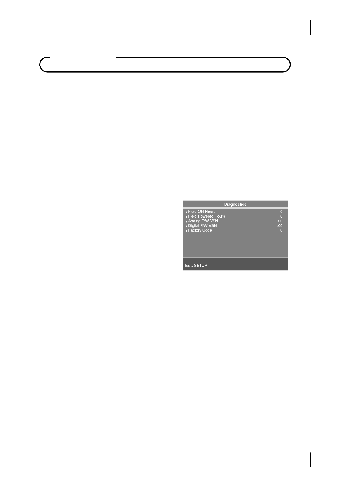
Diagnostics
This menu provides readouts of the TV’s internal
operation. The Diagnostics menu items are readonly and can not be changed.
Field ON Hours
Field Powered Hours
Analog F/W VSN:
Digital F/W VSN
Factory Code
: Cumulative time TV is actually on
: Cumulative time TV is powered.
Analog Firmware Version.
: Digital Firmware Version.
: Use for Factory Diagnostics
CH▲ / CH▼
button to select your viewing area time zone;
button to select Digital Mode Time Setup.
button to select Daylight Saving.
button to select Auto, On, Off depending on whether or not your
45 Document Number: PD196-103 Rev 1
Page 46
Features
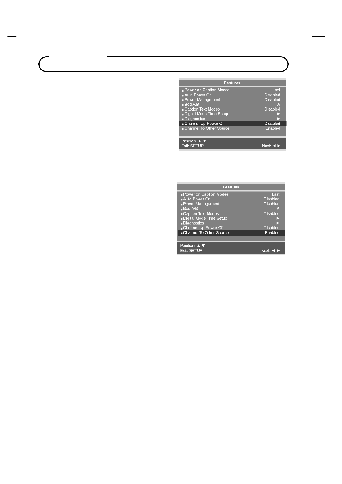
Channel Up Power Off
This feature causes the TV to turn off once it reaches
the highest numbered (last) channel. When the feature
is disabled, the TV will continue on to the lowest
channel and not turn off.
1. In
Features menu, press the
button to select Channel Up Power Off.
2.
Press the
Enabled or Disabled.
3.
Press the SETUP button to return to the
preceding menu.
VOL◄ / VOL►
CH▲ / CH▼
button to select
Channel To Other Source
External signal sources connected to the TV such
as DVD players or Game Boys are shown in the
current channel lineup after the highest channel
and then shown on the TV. Set this feature to
Disabled to require the activation of the external
sources via a key press of the TV’s front “TV/AV”
button.
1.
In Features menu, press the
button to select Channel To Other Source.
2.
Press the
Enabled or Disabled.
Press the SETUP button to return to the
3.
preceding menu.
VOL◄ / VOL►
CH▲ / CH▼
button to select
46 Document Number: PD196-103 Rev 1
Page 47
e
FM Radio
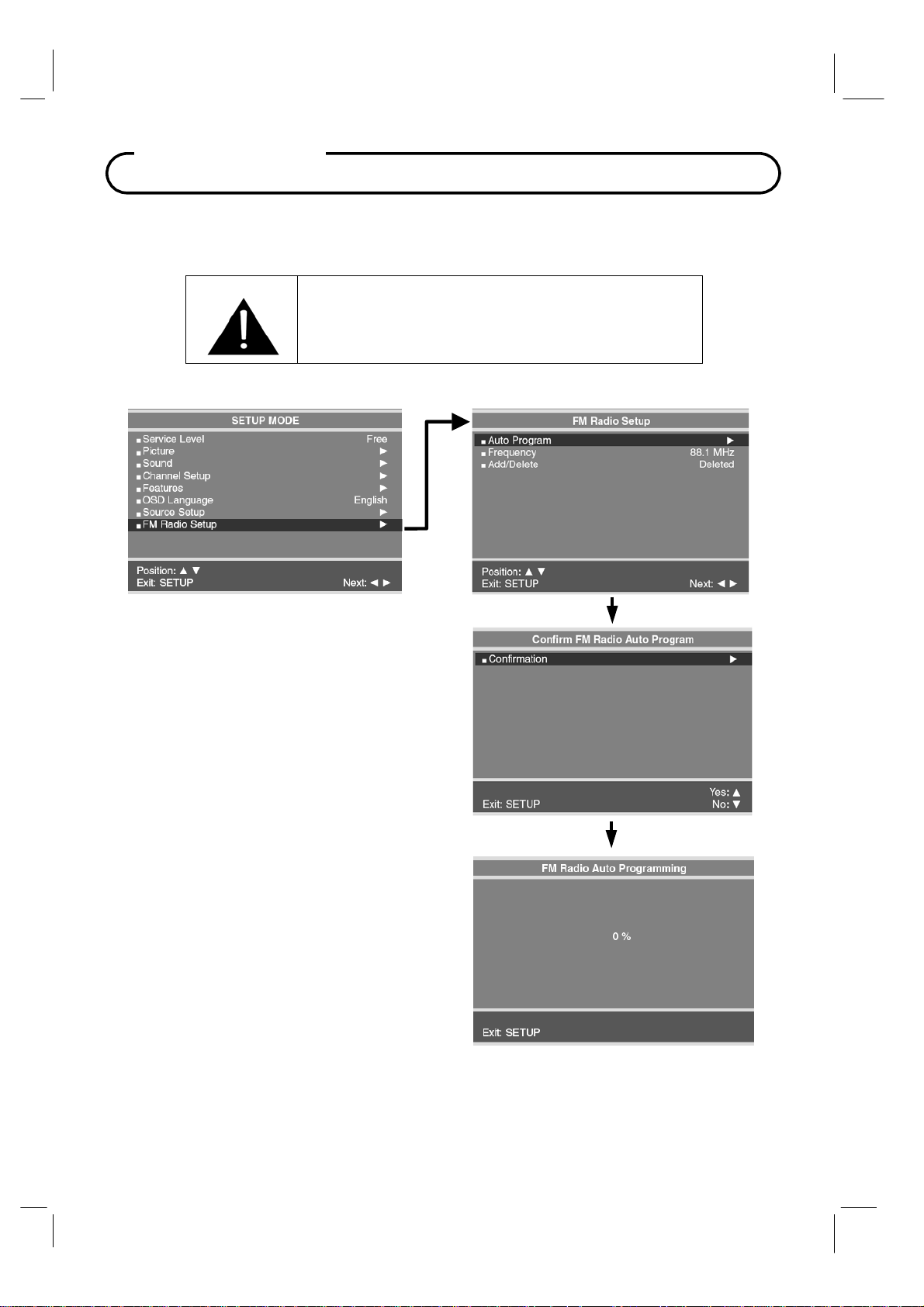
FM Radio Setup
You can listen to FM radio stations that are combined with the cable TV signals using this TV.
IMPORTANT: The FM radio source must be
enabled in the SOURCE SETUP menu before
using the FM Radio setup menu.
Auto Program
1. Press the SETUP button.
2. Press the
FM Radio Setup menu. Then press the
VOL◄ / VOL►
3. Press the
automatically scan.
4. Press the
Radio
CH▼=No). The TV will now search all
available radio channels looking for signals
and memorizing those radio channels that ar
active.
5.
Press the SETUP button to return to FM
Radio Setup
Add/Delete Stations
1. Select the Frequency you wish to Add or
Delete.
2. To delete a frequency from memory, press
the CH▲ / CH▼ button to select Add/Delete.
3. Select off with the VOL◄ / VOL► to Add or
Delete the frequency.
4. Press the Setup button to return to the FM
Radio Setup menu.
CH▲ / CH▼
VOL◄ / VOL►
CH▲ / CH▼
Auto Program. (CH▲=Yes,
menu.
button to select the
buttons to enter the menu.
button to
button to Confirm FM
47 Document Number: PD196-103 Rev 1
Page 48
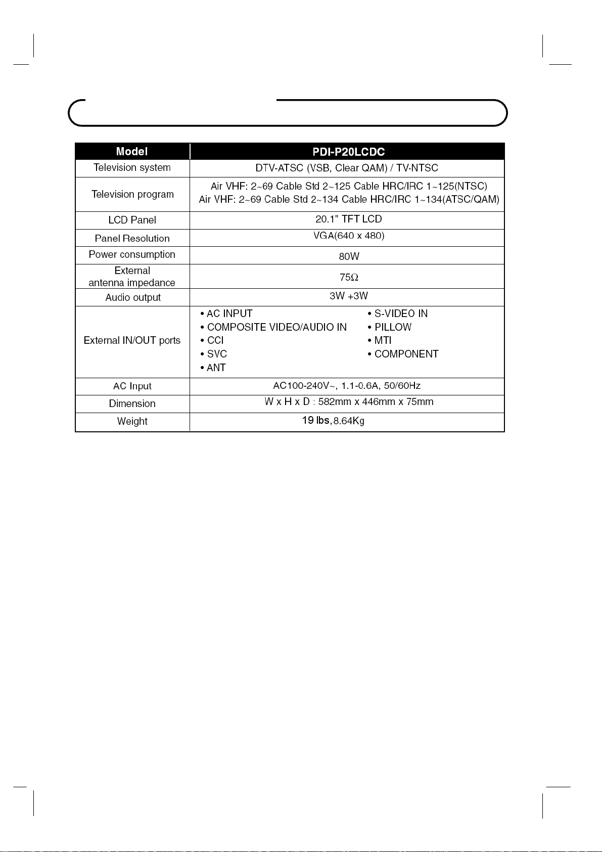
Specifications*
* All rights reserved for technical modifications.
48 Document Number: PD196-103 Rev 1
Page 49
T
g
roubleshootin
PROBLEM CHECK
No Picture on Screen, No Sound from
Speakers
No Picture, Sound OK
Picture OK, No Sound
No Sound from Internal TV Speakers
Picture is too Light
Picture is too Dark
Remote Control does not work
Picture is not sharp. Picture moves or jitters.
• Make sure the TV set is powered – Power
indicator is Red.
• Turn on the TV using the “ON/OFF”
power button.
• Make sure a source is selected (Enabled
from menu)
• Check the Brightness setting of the TV.
• Internal LCD panel lamps may have
failed.
• If a secondary source is selected, verify
the Video input signal is connected.
• Check the Volume settings.
• Verify the Sound has not been muted.
• Verify the pillow speaker is connected
with the pillow speaker volume wheel
adjusted for proper sound.
• If a secondary source is selected, verify
the audio input signal is connected.
• Verify TV speaker has not been disabled
in the “Internal Speaker Disable” setup
menu.
• Verify the Sound has not been muted.
• Verify correct color and contrast settings.
• Verify Brightness setting correct and not
too low.
• Internal LCD Panel lamps may have
failed.
• Change the remote’s batteries.
• Verify the TV’s IR window is not flooded
with strong lights such as from fluorescent
lamps.
• For a Patient Remote, verify correct Bed
Code settings.
• The cable TV signal may be weak.
• Verify the coax cable is connected.
Picture has ghost images
Stripes or Dots move through picture
49 Document Number: PD196-103 Rev 1
• The cable TV signal may be weak.
• The coax cable connection may be loose.
• Possible interference from nearby hospital
equipment.
• The cable TV signal may be weak.
Page 50

t
A
t
A
t
r
r
t
r
Limited Warranty
NOTE: Opening the TV set, or attempting a repair by
non-PDI personnel will void the Warranty!
PDI Communication Systems Inc., (“PDI”) warrants, to the original purchaser only, that this
television will be free from defects in materials and workmanship, under normal use, for 2
years from the date of original purchase. This warranty does not cover any other equipmen
that may have been included with PDI’s shipment of this product.
fter receipt of written notice of a defect or malfunction occurring during the warranty period,
PDI will repair or replace goods returned to its Springboro, Ohio location, at its discretion,
free of charge to the original purchaser, the whole or any component part of any produc
manufactured by PDI and found by PDI to be defective.
s a condition to obtaining warranty service, written notification must be received by PDI
within at least ten (10) days after defect is first observed. Repair of said product requires i
to be shipped to the PDI factory in Springboro, Ohio. All shipments shall be F.O.B.
Springboro, Ohio, and all shipping and freight charges to PDI’s factory shall be paid by the
customer.
This warranty shall not apply to any PDI products subjected to improper use, negligence o
accident; nor to tampering, alterations, or repairs by others, without PDI’s specific prio
written authorization. For information regarding authorized servicing and all other
information pertaining to this warranty, please contact PDI COMMUNICATION SYSTEMS a
40 Greenwood Lane, Springboro, Ohio 45066 or phone 937-743-6010.
This warranty gives specific legal rights and you may also have other rights which vary from
state to state.
PDI’s liability under this warranty is limited to repair or replacement of defective products
and parts as provided above. PDI shall not be liable for incidental or consequential
damages.*
The warranty contained herein is in lieu of all other expressed or implied warranties,
including any implied warranty of merchantability or fitness for any particular purpose. PDI
neither assumes nor authorizes any person to assume, on its behalf, any other obligation o
liability.
*Some states do not allow the exclusion of limitation of incidental or consequential damages or a
disclaimer of warranties implied by law, so the above limitation or exclusion may not apply.
50 Document Number: PD196-103 Rev 1
Page 51

PDI Communication Systems, Inc.
40 Greenwood Lane
Springboro, Ohio 45066
PH: 937-743-6010 FX: 937-743-5664
WEB: PDIARM.COM
P/No : 104937 (GPN07MA001C)
Printed in Korea
.
51 Document Number: PD196-103 Rev 1
 Loading...