

PDi DM68 Instruction Manual
HANDHELD
DIGITAL MULTMETER
OPERATOR'S
INSTRUCTION MANUAL
Table
of
Contents
TlTL
E
PAGE
1.
GENERAL INSTRUCTIONS
1
1.1
Precaution safety measures
1.1 .I
Preliminary
1.1.2
During use
1.1.3
Symbols
1.1.4
Instructions
2.
DESCRIPTION
6
2.1
Instrument Familiarization
2.2
LCD Display
2.3
Key pad
2.4
Rotary switch
2.5
Terminals
2.6
Accessories
11
3.
FUNCTION DESCRIPTION
12
3.1
General Functions
12
3.1
.I
DATA HOLD mode
12
3.1.2
Manual ranging and Autorange mode
12
3.1.3
Battery saver
13
3.2
Measurement Functions
3.2.1
AC and DC Voltage measurement
I
3.2.2
Resistance measurement
3.2.3
Diode Test
3.2.4
Continuity Check
3.2.5
Capacitance measurement
3.2.6
Frequency measurement
3.2.7
Transistor measurement
3.2.8
Current measurement (with clamp,optional)
19
3.2.9
Current measurement
20
Table of Contents
4.
TECHNICAL SPECIFICATIONS
4.1 General specifications..
4.2 Measurement specifications
4.2.1 DC Voltage
4.2.2 AC Voltage
4.2.3 Resistance
4.2.4 Diode Test
4.2.5 Continuity Check
4.2.6 Transistor
4.2.7 Capacitance
4.2.8 Frequency
4.2.9 Current (with clamp. optional)
4.2.10 DC Current
4.2.11 AC Current
5.
MAINTENANCE
5.1 General maintenance
5.2 Battery and fuse replacement
6.
HOW
TO USE THE HOLSTER
PAGE
21
21
22
22
22
23
23
23
23
24
24
24
.25
25
1. GENERAL INSTRUCTIONS
This instrument complies with IEC 1010-1
(61010-l@IEC:
2001), CAT. II 1000V and CAT. Ill 600V overvoltage standards.
See Specifications.
To get the best service from this instrument, read carefully this
user's manual and respect the detailed safety precautions.
International symbols used on the Meter and in this manual
I
are explained in chapter 1
.I
.3
1
.I
Precautions safety measures
1.1.1
Preliminary
Measurement category
Ill is for.measurements performed in
the building installation.
NOTE: Examples are measurements on distribution boards,
circuit-breakers, wiring, including cables, bus-bars, junction
boxes, switches, socket-outlets in the fixed installation, and
equipment for industrial use and some other equipment, for
example, stationary motors with permanent connection to
the fixed installation.
Measurement category II is for measurements performed on
circuits directly connected to the low voltage installation.
NOTE: Examples are measurements on household
appliances, portable tools and similar equipment.
*
Measurement category I is for measurements performed on
circuits not directly connected to MAINS.
NOTE: Examples are measurements on circuits not derived
from MAINS, and specially protected (internal) MAINS
derived circuits. In the latter case, transient stresses are
variable; for that reason, requires that the transient
withstand capability of the equipment is made known to the
user.
'
When using this Multimeter, the user must observe all
normal safety rules concerning:
-
protection against the dangers of electric current.
-
protection of the Multimeter against misuse.
For your own safety, only use the test probes supplied with
the instrument. Before use, check that they are in good
condition.
1.1.2
During use
If the meter is used near noise generating equipment, be
aware that display may become unstable or indicate large
errors.
'
Do not use the meter or test leads if they look damaged.
Use the meter only as specified in this manual; otherwise,
the protection provided by the meter may be impaired.
Use extreme caution when working around bare conductors
or bus bars.
*
Do
not operate the meter around explosive gas, vapor, or dust.
Verify a Meter's operation by measuring a known voltage.
Do not use the Meter if it operates abnormally. Protection
may be impaired. When in doubt, have the Meter serviced.
Uses the proper terminals, function, and range for your
measurements.
When the range of the value to be measured is unknown,
check that the range initially set on the multimeter is the
highest possible or, wherever possible, choose the
autoranging mode.
'
To avoid damages to the instrument, do not exceed the
maximum limits of the input values shown in the technical
specification tables.
"
When the multimeter is linked to measurement circuits, do
not touch unused terminals.
2
Caution when working with voltages above 6OVdc or 3OVac
rms. Such voltages pose a shock hazard.
When using the probes, keep your fingers behind the finger
guards.
When making connections, connect the common test lead
before connecting the live test lead; when disconnecting,
.
I
disconnect the live test lead before disconnecting the
common test lead.
Before changing functions, disconnect the test leads from
f
the circuit under test.
For all dc functions, including manual or auto-ranging, to
avoid the risk of shock due to possible improper reading,
verify the presence of any ac voltages by first using the ac
function. Then select a dc voltage range equal to or greater
than the ac range.
Before attempting to insert transistors for testing. always be
sure that test leads have been disconnected from any
measurement circuits.
.
'
Components should not be connected to the hFE socket
when making voltage measurements with test leads.
Disconnect circuits power and discharge all high-voltage
capacitors before testing resistance, continuity, diodes, or
capacitance.
Never perform resistance or continuity measurements on
live circuits.
Before measuring current, check the meter's fuse and turn
off power to
the circuit before connecting the meter to the
circuit.
*
In N repair work, or when carrying out measurements on
power switching circuits, remember that high amplitude
voltage pulses at the test points can damage the multimeter.
Use of a
TV
filter will attenuate any such pulses.
3
*
Use the
9V
NEDA battery, properly installed in the Meter's
battery case, to power the Meter.
Replace the battery as soon as the battery indicator
(
a
)
appears. With a low battery, the Meter might produce false
readings that can lead to electric shock and personal injury.
Do not measure voltages above
600V
in Categoly
Ill,
or
lOOOV
in Category
I1
installations.
Do not operate the Meter with the case (or part of the case)
removed.
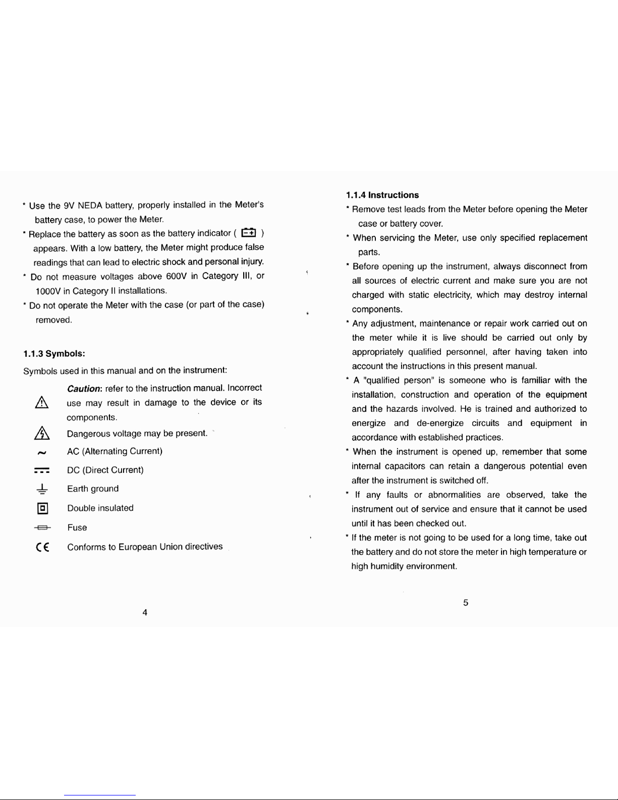
1.1.3
Symbols:
Symbols used in this manual and on the instrument:
Caution:
refer to the instruction manual. Incorrect
use may result in damage to the device or its
components.
Dangerous voltage may be present.
w
AC (Alternating Current)
-
-
-
-
DC (Direct Current)
&
Earth ground
Double insulated
8
Fuse
C
<
Conforms to European Union directives
1.1.4
Instructions
Remove test leads from the Meter before opening the Meter
case or battery cover.
'
When sewicing the Meter, use only specified replacement
parts.
"
Before opening up the instrument, always disconnect from
5
all sources of electric current and make sure you are not
charged with static electricity, which may destroy internal
components.
Any adjustment, maintenance or repair work carried out on
the meter while it is live should be carried out only by
appropriately qualified personnel, after having taken into
account the instructions in this present manual.
'
A "qualified person" is someone who is familiar with the
installation, construction and operation of the equipment
and the hazards involved. He is trained and authorized to
energize and de-energize circuits and equipment in
accordance with established practices.
'
When the instrument is opened up, remember that some
internal capacitors can retain a dangerous potential even
after the instrument is switched off.
*
If any faults or abnormalities are observed, take the
instrument out of service and ensure that it cannot be used
until it has been checked out.
*
If the meter is not going to be used for a long time, take out
the battery and do not store the meter in high temperature or
high humidity environment.
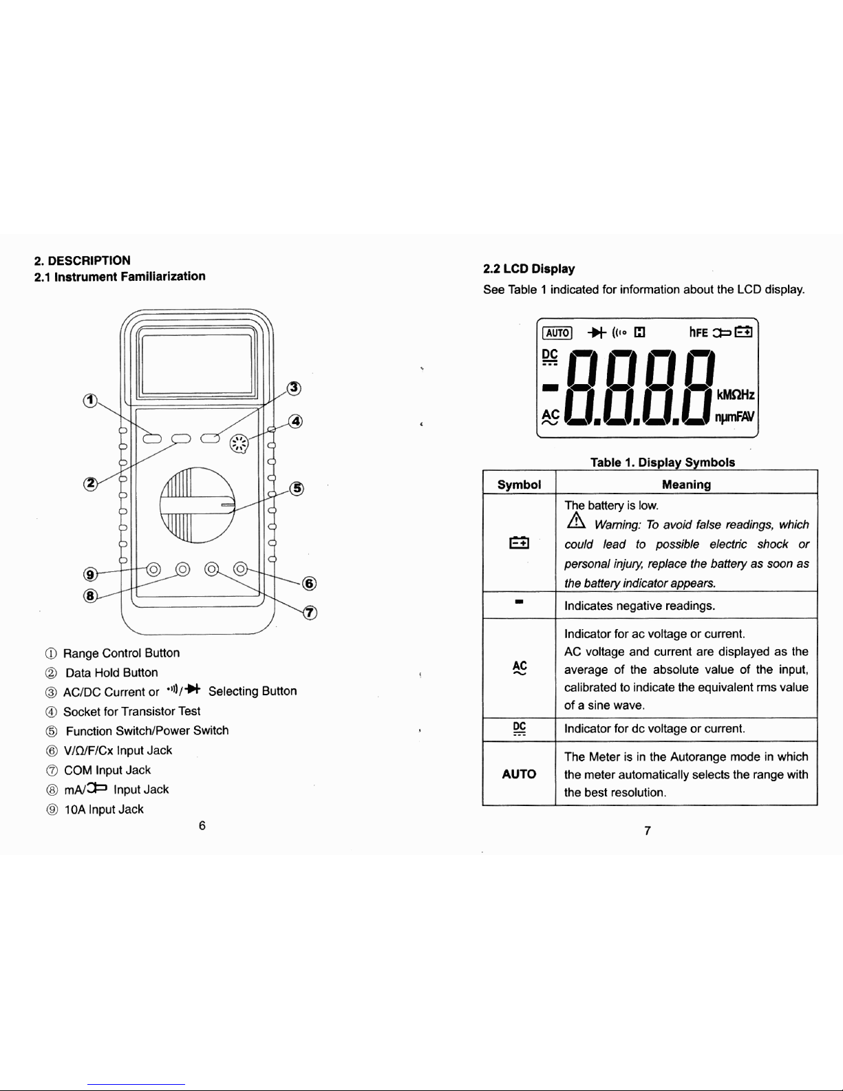
2.
DESCRIPTION
2.1
Instrument Familiarization
a
Range Control Button
Q
Data Hold Button
@
ACIDC Current or
'I))/*
Selecting Button
@
Socket for Transistor Test
@
Function SwitcWPower Switch
@
V/n/F/Cx
lnput Jack
COM lnput Jack
@
m~/* lnput Jack
@
10A
lnput Jack
2.2
LCD
Display
See Table
1
indicated for information about the LCD display.
Indicator for ac voltage or current.
AC voltage and current are displayed as the
average of the absolute value of the input.
calibrated to indicate the equivalent
rms value
of a sine wave.
---
Indicator for dc voltage or current.
Table
1.
Display Symbols
Symbol
Meaning
The battery is low.
Warning: To avoid fake readings, which
wuld lead to possible electric shock or
personal injury, replace the battery as soon as
the
baffery indicator appears.
Indicates negative readings.
AUTO
The Meter is in the Autorange mode in which
the meter automatically selects the range with
the best resolution.
 Loading...