

PDi 879RMS Operating Instructions Manual
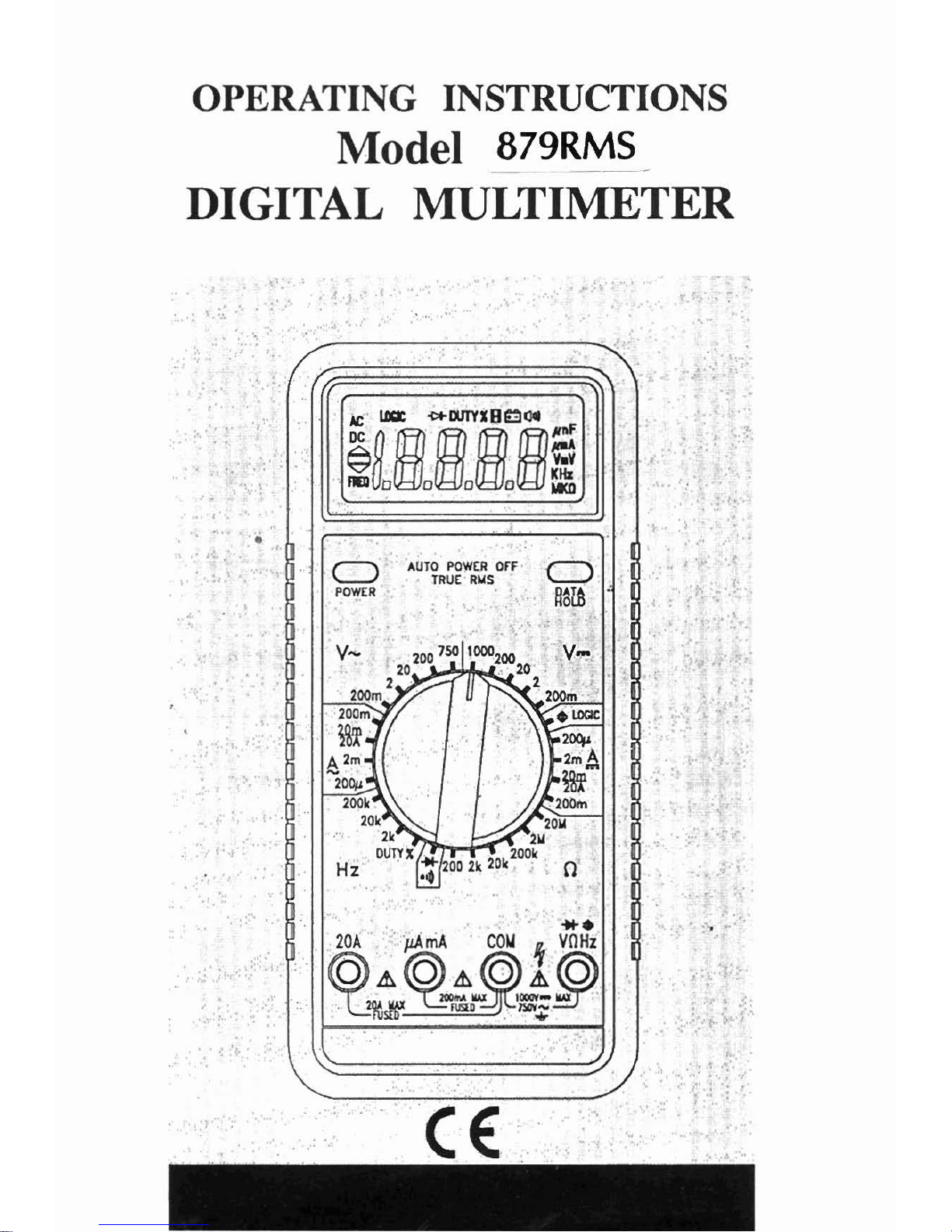
OPERATING INSTRUCTIONS
Model
879RMS
DIGITAL
MULTIMETER
CONTENTS
HOW TO
MAKE MEASUREMENTS
..................................
&
voltage Measurements
8
Current Measurements
9
Resistance Measurements 1 1
Continuity
the ti^^
I1
Diode Testing 11
LogicTesting 11
Frequency and Duty Cycle Measurements
12
INTRODUCTION
This manual contains information and warnings which must be followed
to ensure safe operation and retain the meter in safe condition.
WARNING
READ "SAFETY INFORMATION" BEFORE USING THE METER.
This multimeter is a handheld, 20000-count instrument that is designed
for use in the laboratory, field servicing, and at home. This meter
features compact design with rounded corners for easy handling and has
a rugged case in shock resistant and fire-retardant. Electronic overload
protection for all functions and ranges. The Protective Holster (optional
accessory) combined with rugged case make it a durable and reliable
instrument.
UNPACKING
AND
INSPECTION
Upon removing yournew Digital Multimeter (DMM) from its packing,
you should have the following items:
1. Digital Multimeter
I
2.
Test Lead Set (one black, one red)
3.
9-Volt Battery (installed in meter)
i
4.
Instruction Manual
5.
One Spare Fuse (500mA/600V, 6.3mm x 25mm, fast acting)
If any of the above items are missing or are received in a damaged
cond~tion, pleasecontact thedistributor from whom you purchased the
unit.
SAFETY INFORMATION
Injury or death can occur even with low voltages and low currents. It
is extremely important that you read these safety information before
using yourmultimeter. Follow all safety practices and proper operating
procedures for equipment being tested.
I. Exercise extreme caution when:
Measuring voltage above 20 volts, measuring current greater
than
IOmA, measuring AC power line with inductive loads, measuring
AC power line during electrical storms.
2.
Always inspect your DMM, test leads and accessories for
any
sign
of damage or abnormality before every use. If any abnormal
conditions exist
(i.e., broken or damaged test leads, cracked case,
display not reading, etc.), do not attempt to
takeany measurements.
3.
Never ground yourselfwhen taking electrical measurements. Do not
touch exposed metal pipes, outlets, fixtures, etc., which might beat
ground potential. Keep your body isolated from ground by using dry
clothing, rubber shoes, rubber mats, or any approved insulating
material.
4.
Never touch exposed wiring, connections, test probe tips, orany live
circuit conductors when attempting to make measurements.
5. Never replace the protective fuse inside the DMM with a fuseother
than the specified or approved equal fuse.
6.
Do not operate this instrument in an explosive atmosphere (i.e., in
the presence of flammable gases or fumes, vapor or dust.)
7.
Measuring voltage which exceeds the limits
of
the multimeter may
damage the meter and expose theoperator to a shock hazard. Always
recognize
themeter voltage limits as stated on the front of the meter.
8.
Never apply more than 5OOVDC between the COM jack and earth
ground.
9.
Never touch a voltage source when the test leads are plugged into
a current jack.
10. When testing for the presence of voltage or current, make sure the
voltage or current ranges are functioning correctly. Take a reading
of a known voltage or current before assuming a zero reading
indicates no current or voltage.
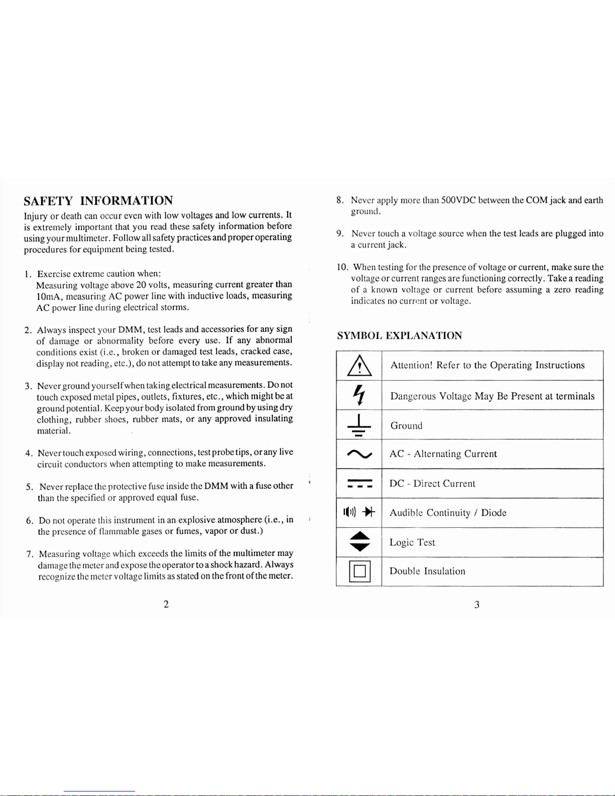
SYMBOL
EXPLANATION
1-
-
-
-
,
,
,
l(1))
A
Attention! Refer to the Operating Instructions
Dangerous Voltage May Be Present at terminals
Ground
AC
-
Alternating Current
DC
-
Direct Current
Audible Continuity
/
Diode
Logic Test
Double Insulation
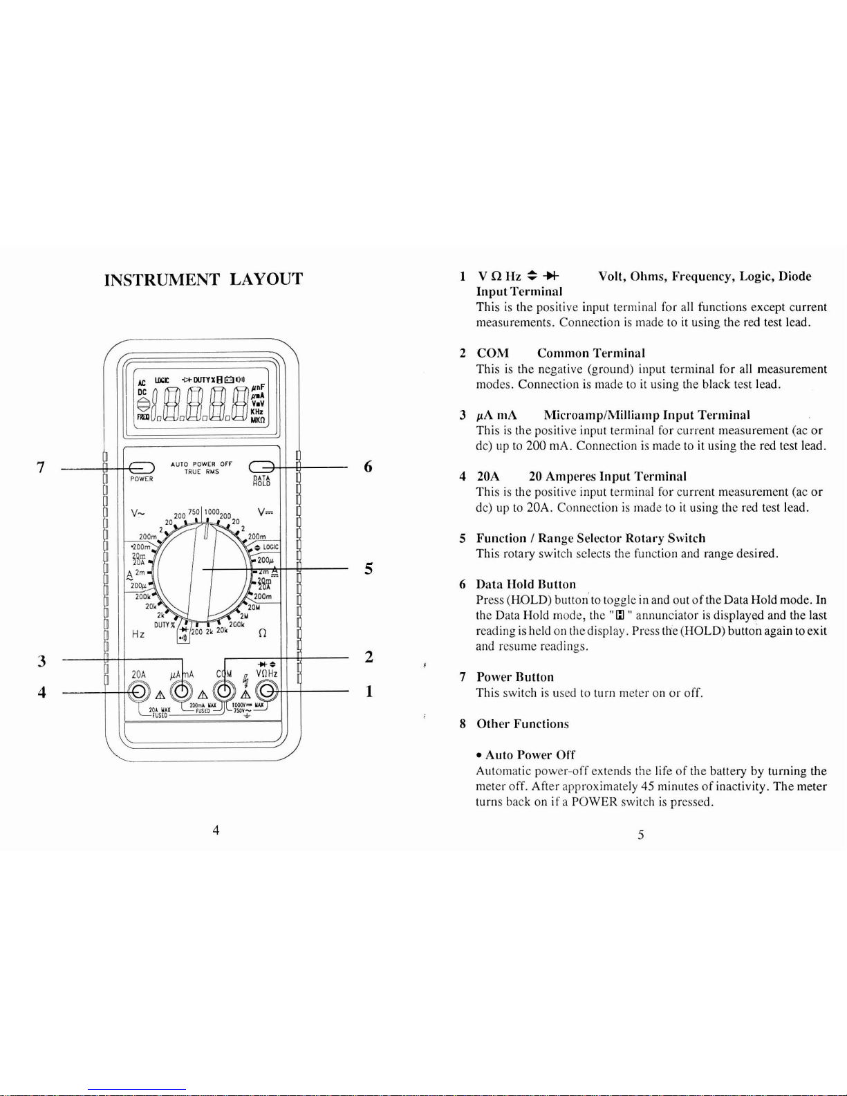
INSTRUMENT
LAYOUT
1 VQHz=-H
Volt, Ohms, Frequency, Logic, Diode
Input Terminal
This is the positive input
terminal for all functions except current
measurements. Connection is
made to it using the red test lead.
2
COM Common Terminal
This is the negative (ground) input
terminal for all measurement
modes. Connection is made to it using the black test lead.
3
pA niA MicroamplMilliamp Input Terminal
This is the positive input terminal for current measurement (ac or
dc) up to
200
mA. Connection is made to it using the red test lead.
6
4
20A
20
Amperes Input Terminal
This is the positive input terminal for current measurement (ac
or
dc) up to 20A. Connection is made to it using the red test lead.
5
Function I Range Selector Rotary Switch
This rotary switch selects the function and range desired.
5
6
Data Hold Button
Press
(HOLD) buttonto toggle in and out of the Data Hold mode. In
the Data Hold mode, the
"
13
"
annunciator is displayed and the last
reading is held on thedisplay. Press the (HOLD) button again to exit
and resume readings.
3
A
I
7
Power Button
1
This switch is used to turn meter on or off.
8
Other Functions
Auto Power Off
Automatic power-off extends the life of the
battery by turning the
meter off. After approximately
45
minutes of inactivity. The meter
turns back on if a POWER switch is pressed.
 Loading...