

PDi 872 Operating Instructions Manual
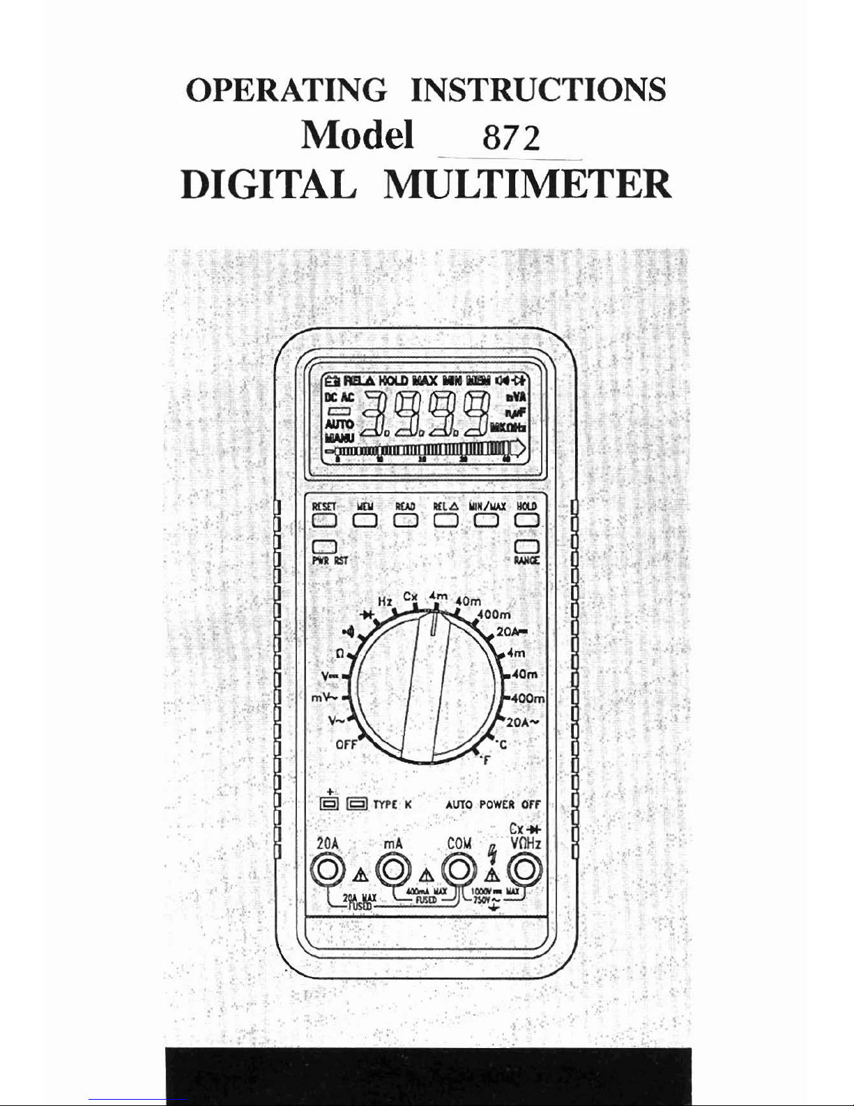
OPERATING INSTRUCTIONS
Model
872
DIGITAL
MULTIMETER
CONTENTS
INTRODUCTION
This manual contains informationand warnings which must be followed
to ensure safe operation and retain the meter in safe condition.
WARNING
READ "SAFETY INFORMATION" BEFORE
USING
THE
METER.
This multimeter is a handheld, 4000-count instrument that is designed
for use in the laboratory, field servicing, and at home. The meter
I
combines the precision of a digital multimeter with the high speed and
versatility of a analog display. This meter features
compact design with
rounded corners for easy handling and has a rugged case in shock
resistant and fire-retardant. Electronic overload protection for all
functions and ranges. The Protective Holster (optional accessory)
combined with rugged case make it a durable and reliable instrument.
UNPACKING AND INSPECTION
Upon removing your new Digital MuItimeter(DMM) from its packing,
you should have the following items:
1.
Digital Multimeter
2. Test Lead Set (one black, one red)
'
3. 9-Volt Battery (installed in meter)
4.
Beaded Thermocouple Wire
5. Instruction Manual
6.
One Spare Fuse (500mA/600V, 6.3mm x 25mm, fast acting)
f
If
any of the above items are missing or are received in a damaged
cond~tion, please contact thedistributor from whom you purchased the
unit.
SAFETY
INFORMATION
Injury or death can occur even with low voltages and low currents. It is
extremely importantthat you read thesesafety information beforeusing
your multimeter. Follow all safety practices and proper operating
procedures for equipment being tested.
1.
Exercise extreme caution when:
Measuring voltage above 20 volts, measuring current greater than
IOmA, measuring AC power line with inductive loads, measuring
AC power line during electrical storms.
2.
Always inspect your DMM, test leads and accessories for any sign
of damage or abnormality before every use. If any abnormal
conditions exist
(i.e., broken or damaged test leads, cracked case,
display not reading, etc.), do not attempt to take any measurements.
3.
Never ground yoilrselfwhen taking electrical measurements. Do not
touch exposed metal pipes, outlets, fixtures, etc., which might be at
ground potential. Keep your body isolated from ground by using dry
clothing, rubber shoes, rubber mats, or any approved insulating
material.
4.
Never touch exposed wiring, connections, test probe tips, or any live
circuit conductors when attempting to make measurements.
5.
Never replace the protective fuse inside the DMM with a fuse other
than the specified or approved equal fuse.
6.
Do not operate this instrument in an explosive atmosphere (i.e., in
the presence of flammable gases or fumes, vapor or dust.)
7.
Measuring voltage which exceeds the limits of the multimeter may
damage the meter and expose the operator to
ashock hazard. Always
recognize
themeter voltage limits as stated on the front ofthe meter.
8.
Never apply more than SOOVDC between the COM jack and earth
ground.
9.
Never touch a voltage source when the test leads are plugged into
a
current jack.
10. When testing for the presence of voltage or current, make sure the
voltage or current ranges are functioning correctly. Take a reading
of a known voltage or current before assuming a zero reading
indicates no current or voltage.
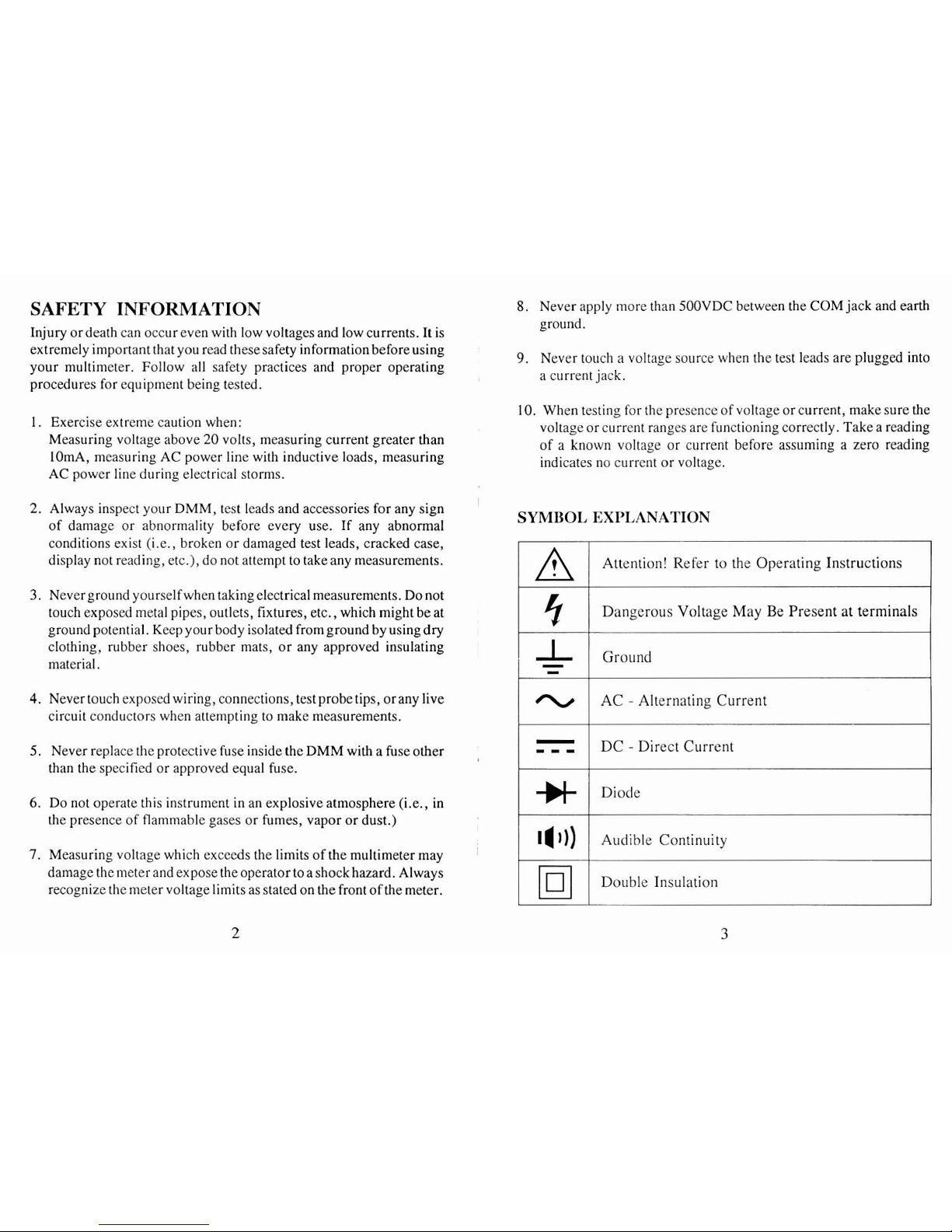
SYMBOL
EXPLANATION
9
-L
-
-
-
, ,
,
14
I))
Attention! Refer to the Operating Instructions
Dangerous Voltage May Be Present at terminals
Ground
AC
-
Alternating Current
DC
-
Direct Current
Diode
Audible Continuity
Double Insulation
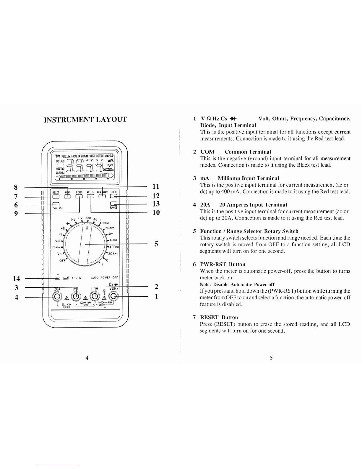
INSTRUMENT LAYOUT
1
VQHzCx* Volt, Ohms, Frequency, Capacitance,
Diode, Input Terminal
I
This is the positive input terminal for all functions except current
I
measurements. Connection is made to it using the Red test lead.
1
2
COM Common Terminal
This is the negative (ground) input terminal for all measurement
modes. Connection is made to it using the Black test lead.
3
mA
Millianlp Input Terniinal
11
This is the positive input terminal for current measurement (ac or
I
12
dc) up to
400
mA. Connection is made to it using the Red test lead.
13
4
20A
20
Amperes Input Terminal
10
This is the positive input terminal for current measurement (ac
or
dc) up to
20A.
Connection is made to it using the Red test lead.
I
'
5
Function I Range Selector Rotary Switch
This rotary switch selects function and range needed. Each time the
5
rotary switch is ~iioved from
OFF
to a function setting, all LCD
~
segments will turn on for one second.
6
PWR-RST Button
When the meter is automatic power-off, press the button to turns
meter back on.
Note: Disable Aulomntic Power-off
Ifyou press and hold down the (PWR-RST) button while turning the
meter from
OFF
to on and select a function,
theautomatic power-off
feature is disabled.
7
RESET Button
Press (RESET) button to erase the stored reading, and all LCD
segments will
turn on for one second.
 Loading...