

PD CERASIS DG 600/270, DG 600/320 Assembly Instructions Manual
- 1 -
DG 600/270 and DG 600/320
Assembly instruction
- 2 -
Building of model DG 600
Wing:
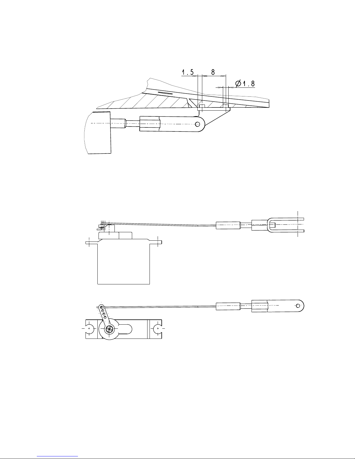
The next picture shows the aileron servo installation as viewed from the front of the wing. Open up the covering over
the aileron servo bays with a sharp hobby knife and remove any material that fills the bays down to the wood. Guide the servo
wires through the routed wing channels until the connectors on the end of the wires emerge from the wing roots. Make sure
the aileron servos are facing the right direction and adjust the position of the aileron servo arm by connecting the servo wire to
the receiver, connecting the battery to the receiver, then turn the transmitter on. Make sure all trims are centered and your
servo will be in the neutral position. Adjust the servo arm by removing the servo arm screw and push the servo arm back on
with the servo arm facing forward (in respect to the plane) at an angle of 40 degrees from the wing surface.
Once you‘re sure you have the servos in the correct position and they fit well in the wing bays, disconnect them from
the receiver, turn off the transmitter and glue or double-sided tape the servos in place in the wing. Place and then attach the
aileron control horns on the ailerons directly back from the servo arms and install the linkage. The throws for the aileron
should be 15 degrees up and 7 degrees down. If you have a computer radio, program you first settings for these values. If
your radio is programmable, you can adjust the aileron deflections using this feature. If you radio does not permit this
adjustement, then manually adjust the servos as shown in the picture.
- 3 -
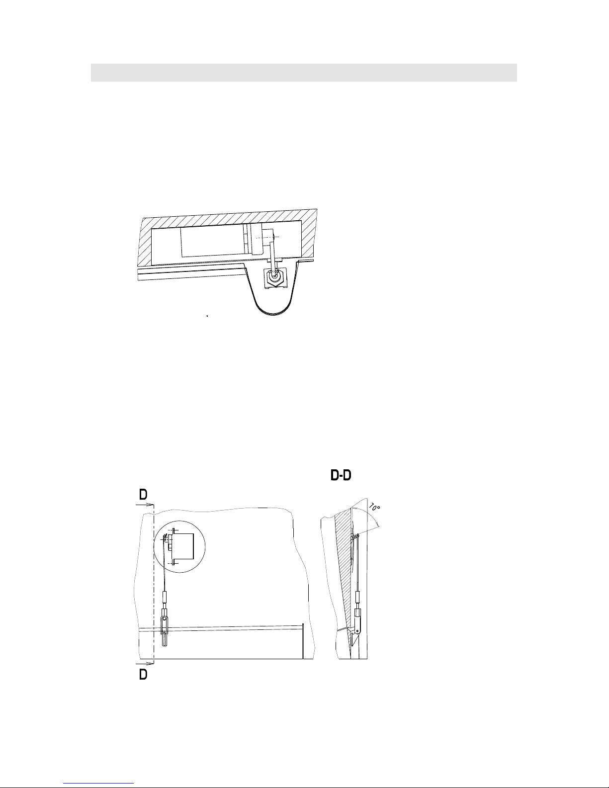
Note the drawing of the aileron horn and the servo arm. The arm should be set at 70° with the radio on, all trims set at
zero, and the aileron horizontal to the wing.
The wire pushrod is attached to the clevis using a threaded coupler.
 Loading...