

PDA Range VL1 Instructions Manual
VL1
12VMINI AUDIO-FREQUENCY
INDUCTIONLOOPAMPLIFIER
Approved document No. DCM0003479 Rev 1 • Page 1 of 8
The VL1 is a true current mode audio-frequency induction loop amplifier. Its compact
design, 12V d.c. operation and availability in a variety of kit formats make it ideally
suited for use in:-
• Cars, taxis, buses and other private/commercial vehicles (VL1/B1 or VL1/B2 kits)
• Ticket counters and other desktop applications (VL1/C kit)
• Access control applications (VL1/A kit)
In addition to this instruction manual, all of the above kits include Quick Start installation
guides specific to the application(s) for which they are intended. These guides should
always be referenced in conjunction with this manual prior to installation.
Important notes ................................................................................................................................... 2
Safety guidelines .................................................................................................................................. 2
What is an audio frequency induction loop system? ...................................................................... 3
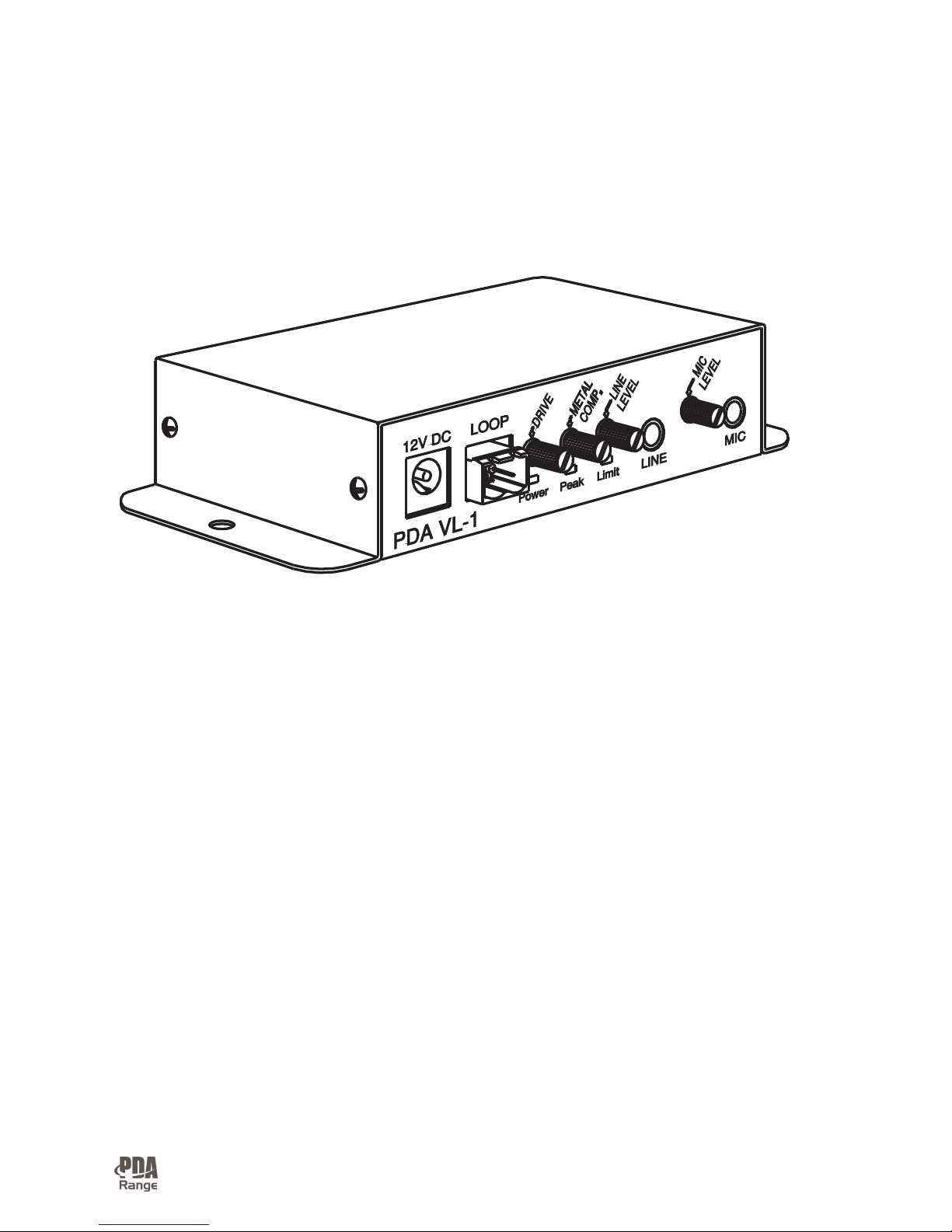
An overview of the VL1 induction loop amplifier ........................................................................... 4
Planning an induction loop system .................................................................................................... 5
Installation, system set-up and testing ........................................................................................... 6/7
T roubleshooting ................................................................................................................................... 8
T echnical specification ......................................................................................................................... 8

Approved document No. DCM0003479 Rev 1 • Page 2 of 8
IMPORTANT NOTES
This equipment must be installed by a suitably skilled and technically competent person.
These instructions are general and cannot be considered to cover every aspect of
audio-frequency induction loop system design and installation.
We recommend you also read BS7594 - The Code of Practice for Audio-Frequency
Induction Loop Systems and EN60118-4 - Magnetic field strength in audio frequency
induction loop systems for hearing aid purposes (or any subsequent revisions), both of
which are available from the British Standards Institute, 389 Chiswick High Road,
London W4 4AL. Tel: +44 (0)20 8996 9000. Web: www.bsi-global.com.
Other National standards of design/installation/commissioning should be referenced
where pertinent.
SAFETY PRECAUTIONS
Avoid placing the VL1 amplifier in areas:-
• with poor ventilation • exposed to direct sunlight
• with high ambient temperatures • adjacent to heat generating equipment
• with high humidity or dust levels • susceptible to severe vibration
DO NOT dismantle or attempt to modify the amplifier in any way. No user-serviceable
fuses or parts are included inside the amplifier. For repair, consult your supplier.
Ensure the loop cable and all relevant audio/microphone and power lead(s) are fixed
securely into position before operation. Do not leave any trailing leads or obstructions.
The VL1 amplifier is capable of producing short-term peaks of twice its rated current.
Approved document No. DCM0003479 Rev 1 • Page 3 of 8
WHAT IS AN AUDIO-FREQUENCY INDUCTION LOOP SYSTEM?
An audio-frequency induction loop system allows hearing impaired
people to hear more clearly. Most hearing aids have a ‘T’ or ‘MT’ switch
which allows them to pick up the electromagnetic field generated by an
induction loop system. The hearing aid converts this signal into a sound
suited to its user’s specific hearing requirements. Any hearing impaired
person positioned within or near the loop can hear the loop signal by
switching their hearing aid to the correct position, allowing them to participate more
effectively in general conversation, ordering goods or services, etc.
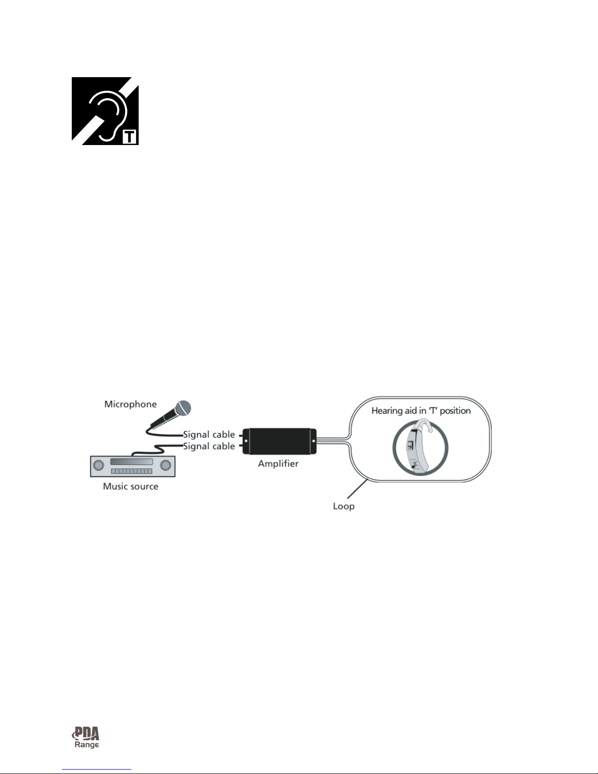
An induction loop system therefore comprises four main elements:The audio source – typically a microphone or a music source (or both).
The induction loop amplifier
The loop – typically a single turn of wire run around the perimeter of the area
requiring coverage or, on smaller systems, a special pre-formed loop fixed to a flat
surface.
The receiver(s) – any behind-the-ear type hearing aid with a ‘T’ or ‘MT’ switch.
 Loading...