

PDA Range PDA200/2, PDA500/2, PDA1000/2 Installation Instructions Manual
PDA200/2, PDA500/2, PDA1000/2
INSTALLATION INSTRUCTIONS
This equipment must be installed by a suitably skilled and technically
competent person. Please read these instructions carefully before installation.
Important notes .......................................................................................... 2
What is an audio frequency induction loop system? .............................. 3
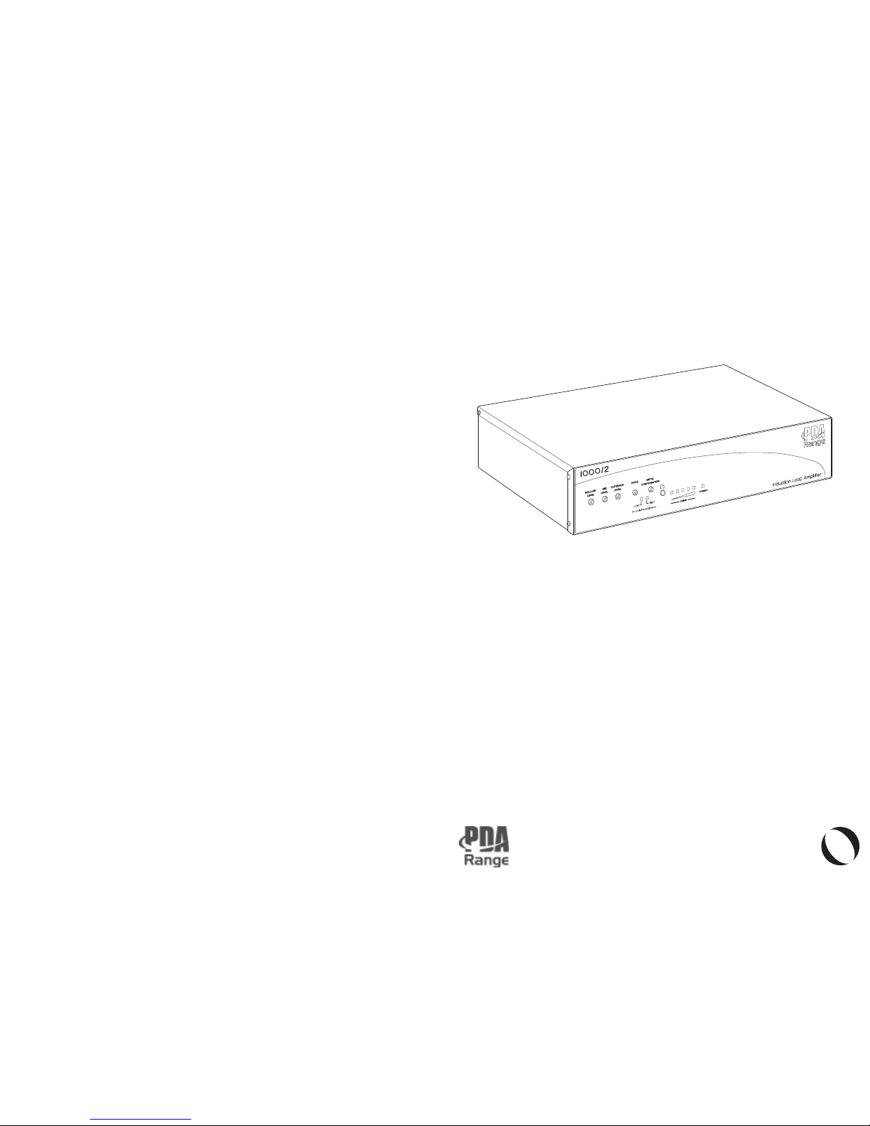
Familiarisation with your PDA Pro-Range induction loop amplifier ..... 4
Planning the system .................................................................................. 6
Overview of the ‘Outreach plate’ audio input extension system .......... 7
A typical PDA Pro-Range induction loop system .................................... 8
Installation ................................................................................................... 11
Safety precautions ..................................................................................... 11
Mounting the amplifier .............................................................................. 11
Connecting and testing the system ......................................................... 12
Technical specification .............................................................................. 14
Spares and accessories .............................................................................. 16
PROFESSIONAL AUDIO-FREQUENCY
INDUCTION LOOP AMPLIFIERS
O
U
T
R
E
A
C
H
C
O
M
P
A
T
I
B
L
PDA Pro-Range Instructions • Approved Doc. No. DCP0003168 Rev 3 • Page 16
© Errors and omiss ions exce pted. The manufacturer of this equipment operates a policy of continuous impr ovement a nd
reserves the right to alter product specifications at its discr etion and without prior notice.
PDA PRO-RANGE A MPLIFIERS AND MOUNT ING KITS
PDA200/2 200m2 free-st andi ng profe ssio nal inducti on loop ampl ifie r
PDA500/2 500m2 free-st andi ng profe ssio nal inducti on loop ampl ifie r
PDA1000/2 900m2 free-st andi ng profe ssio nal inducti on loop ampl ifie r
PDA/ WM Wall mounting kit for PDA200 /2, 500/2 or 1000/ 2 amplifier
PDA/RM 19"Rack mounting kit for PDA200/2, 500/2 or 1000/2 amplifier
INDUCTION LOOP CABLE - see page 6 for further information
LOOP1/B 100m reel 0.5mm2 single core black loop cable
LOOP1/W 100m reel 0.5mm2 single core white loop cable
LOOP2/B 100m reel 1.0mm2 single core black loop cable
LOOP2/W 100m reel 1.0mm2 single core white loop cable
LOOP3/B 100m reel 1.5mm2 single core black loop cable
LOOP3/W 100m reel 1.5mm2 single core white loop cable
LOOP4/B 100m reel 2.5mm2 single core black loop cable
LOOP4/W 100m reel 2.5mm2 single core white loop cable
FLAT1005 1 00m x 0. 5mm2 insula ted copper tape ( flat loop cable for under carpet s)
FLAT2005 100m x 1.0 mm2 insulat ed copper tape (flat loop ca ble for u nder carpets)
FLAT3005 1 00m x 1. 5mm2 insula ted copper tape ( flat loop cable for under carpet s)
TAPE 50m white syntheti c fibre tape (use d to protect flat loop cabl e)
OUTREACH PLATES - see page 7 for further information
APM Omni -di rec tio nal plated micro pho ne, for wall/c eil ing /de sk moun tin g
APL Doubl e phono line level outrea ch plate
APJ 3.5mm mono jack mic. level outreach plate
APQM 6.35mm jack mic. l evel outreach plate
APQL 6.35mm jack line level outreach plate
APXM X LR 3 pin mic level outreach plate
APXL X LR 3 pin line level outreach plate
API AFILS active indicator light
BELDEN/10 10m Belden 87 23 four core screened cable for use with outreach plates
BELDEN/25 25m Belden 87 23 four core screened cable for use with outreach plates
INDUCTION LOOP TESTING EQUIPMENT - see page 13 for fu rther information
SWGN Sine wave g enerator
(requires P P3 battery and AL3 connect ion lead)
AH HM FoS meter magnetic field strength meter
(requires P P3 battery)
AMSW FoSmeter Pl us combined sine wave generator & magnetic field stre ngth meter
(requires PP3 battery and AL3 connection lead)
AHH M/H FoSmet er H combin ed magnetic field strength meter & loop listener
(requires HEAD1 32 Ohm headphones)
HEAD1 32 Ohm h eadphones for u se with AHHM/H
AL3 3.5mm jack to bare ended lead
(connects PNGN or AMPN to a pro-range amplifier’s outreach socket)
INDUCTION LOOP A NCILLARIES
APT Loop connec tor plat e (for the termina tion of indu ctio n loop cable)
LEST 10 0V line (i .e PA system output) to 0 db (775mV line level) convertor
TEAR10 Pack of 10 self-adhesive ‘induction loop in use’ stickers
Spares and accessories
PDA Pro-Range Instructions • Approved Doc. No. DCP0003168 Rev 3 • Page 1

PDA Pro-Range Instructions • Approved Doc. No. DCP0003168 Rev 3 • Page 2
Important notes
These instructions are general and cannot be consider ed to cover every aspect of
audio -fre quen cy inducti on loop system desig n and install atio n.
We recommend you read BS7594 (The Code of Practice for Audio-Frequency Induction
Loop Systems) and EN60118-4 (Magnetic field strength in audio frequency induction loop
systems for hearing aid purposes), copies of which are available from the British Standards
Institute, Customer Services Department, 389 Chiswick High Road, London W4 4AL.
Tel: +44 (0)20 8996 9000. Web: www.bsi-global.com. It should be noted that all of the
above documents can be subject to update or revision at any time and we recommend you
check the status of them with the British Standards Institute before designi ng or insta lling
the system.
Other National standards of design, installat ion and commissioni ng should be refe renced
whe re pert inent .
No responsibility can be accepte d by the manufact urer or distributo rs of this equipment for
any misinterpre tati on of an instr uction or gui dance note or for the complian ce of the
system as a whole.
This induction loop amplifier MUST be installed and maintained by a suitably skilled and
technically competent person.
This document must not be left accessible to the user.
Equipm ent guarantee
This equipment is not guaranteed unless the system is installed and commissioned in
accord ance with National standard s by an approved and competent person or orga nisation.
IMPORTANT : THE INDUCTION LOOP AMPLIFIER SHOULD NEVER
BE OPERATED WITHOUT A LOOP CONNECTED TO IT.
This product has been man ufactured in confor mance with the req uirem ents of
all applicable EU directives.
Compressor: Gives dynamically variabl e compres sion rati o from 1 :1 (no compression ) to 17: 1 when both
compressio n LEDs are lit. In normal use, with th e first co mpression LED lit for part of the ti me, the
compresso r has a “soft knee” charact eristic and provides a small degree of compre ssion for signals which
only just light the first LED but a la rge degree of compressio n for louder peaks.
Attack time: Appro x. 10mS. Re lease time: Approx. 2.2S
Metal Compensat ion: True 3dB /octa ve design counte ract s frequenc y dependen t absorpti on by metal in
the proxim ity of the inst alla tion over a bandwidth of appro ximately 100Hz – 10 KHz.
INDICATORS
Power on LED: Gre en
Loop curre nt: A five LED bar graph type meter is pro vided to allow monitorin g of loop current output and
assis t in setti ng up the amplif ier. This is provi ded by monitorin g true output current rather than from a line
level derived signal. The ca libratio n is as follows:
PDA200/2: 1st led = 75mA 2 nd led = 375mA 3rd led = 1.5A 4th led = 3.75A 5th led = 6A
PDA500/2: 1st led = 112mA 2nd led = 562mA 3rd led = 2.25A 4th led = 5.6A 5th led = 9A
PDA1000/2: 1st led = 150mA 2nd led = 750mA 3rd led = 3A 4th led = 7.5A 5th led = 12A
Accuracy - +-10%
Compression : A two LED display is provided for indication of signal c ompression. The first LED shows the
beginning of compression whilst the sec ond indicates very high compression levels have been reache d.
REAR PANEL CONTROLS
On/Off switch incorpora ted into IEC mains inlet.
Four way piano key style DIP switch selects Phantom power for mic 1 & 2 XLR inputs and switc hes XLR input
1 between Line and Microp hone setting s. The fourth of t he 4-in-line switch is n ot connected .
FRONT PANEL CONTROLS
Level control s for XLR 1 (Line/Mic switchable), XLR 2 (Mic) and Outreach .
These can be used individually or a ny of them together, in whic h case they act as a three input mixer.
Drive control: Sets level of a mpli fier outpu t current suppl ied by the amp lifie r. Ana logou s to the volum e
contro l on a standard voltage output amplifi er but NOT designe d to b e adjusted once set to the correct
value for any give n install atio n.
Metal compens ation cont rol. When fully anti-clo ckwis e has no effect on the signal. When turned clockw ise
imparts a rising 3dB/octave characteristic to the frequ ency response of the amp. This tends to c ounterac t the
effect of m etal in proximity to the loop. Where there is some distanc e between the loop and a ny metal, or
the quantit y of metal is s mall, an inter media te setting of the cont rol should be f ound which provid es a
satis facto ry tonal balanc e.
COOLING REQUIRE MENTS
The PDA1000/2 and PDA500/2 have therm ostati cally controlled cooling fans, which are activated when the
ampli fier ’s internal heatsink temper ature reaches approxi mate ly 56oC. It is therefo re normal for the fans to
be heard switchi ng on an d off i n everyday use.
The P DA200/2 model does not r equire a c ooling fan, as it d oes n ot ge nerate as much heat as t he la rger models.
In all ca ses the a mplifiers should be operated in a cool environment, away from sources of heat and should
never be covered with any object that coul d impede the flow of cooling air.
DIMENSIONS & WEIGHT
All models: Length – 380mm; Depth – 220mm; Height – 80mm
Weight: P DA200/2 – 3.74Kg, PDA5 00/2 – 3.46Kg; PDA100 0/2 – 4.54Kg
PDA Pro-Range Instructions • Approved Doc. No. DCP0003168 Rev 3 • Page 15

PDA Pro-Range Instructions • Approved Doc. No. DCP0003168 Rev 3 • Page 3
An audio-frequency induction loop system (AFILS) allows hearing impaired
people to hear more clearly.
Most hearing aids have a ‘T’ or ‘MT’ switch which allows them to pick up the
electromagnetic field generated by an induction loop system. The hearing aid
converts this signal into a sound suited to its user’s specific hearing requirements.
Any hearing impaired person positioned within or near the loop can hear the loop signal by
switching their hearing aid to the correct position, allowing them to participate more effectively
in general conversation, ordering goods or se rvices, listening to public performances, etc.
An induction loop system therefore comprises four main elements: -
The audio source – typically a microphone, television or radio (or a combination of these).
The indu ction loop ampl ifier
The loop – typically a single turn of wire usually run around the perimeter of the room.
The receiver(s) – any hearing aid with a ‘T’ or ‘MT’ switch.
What is an audio frequency induction loop system?
In addition to having a mic. and a mic./line input (which allows the
above system configuration to be easily implemented), all PDA
Pro-Range amplifiers also have an ‘Outreach’ socket. This socket
offer s full comp ati bility with our unique Outreach plate audio inpu t
extension system and allows the conn ection of mult iple microp hone
O
U
T
R
E
A
C
H
C
O
M
P
A
T
I
B
L
E
and/or line level inputs via a range of specially designed single gang connector plates.
For further details please refer to page 7.
Television
Amplifier
Loop
Microphone
Hearing aid in the
‘T’ or ‘MT’ position
Signal cable
Signal cable
PDA Pro-Range Instructions • Approved Doc. No. DCP0003168 Rev 3 • Page 14
PDA Pro-Range technical specifications
POWER
230-240 V a.c. mains (P DA200/2 <150 VA; PDA500 /2 <225 VA; PDA1000/2 <300 VA)
(IEC 320 fused mains lead supplie d)
INPUTS
Line (3 pin XLR type)
Input impedance: 6k8 + o r – i nput to ground.
Sensitivity : 200mV – 2.5V RMS balanced or un balanced.
Micr oph one s (3 pin XLR type)
Input impedance: 6k8 + o r – i nput to ground.
Sensitivit y: 1 – 8 mV balanced
Phan tom power : 12V switc hab le (on/ off)
Outr eac h (Four -wa y Weidm ull er conn ect or. Plug type BL5. 08/4 )
Inp ut imp eda nce : >10k
Sensitivity : 500mV - 6V RMS balanced
Outreach Power: 16 – 21 V d.c. i s available via the amplifier ’s Outreach Socket. A self-resettin g fuse
prote cts this output from any acciden tal overl oad.
OUTPUT
Type: Current mode.
Loop connect or: Four way bindi ng posts
Recomme nded loop impedance: 0.5 – 1 Ohm @ 1KH z. Will drive highe r impedance loops with reduce d
area of coverag e.
Loop drive current @ 1 Ohm: PDA 200/2 – 6A ; PDA 500/2 – 9A ; PDA 1000/2 – 1 2A.
Pea k loop drive curr ent (meas ur ed ove r 5mS int egr at ion time) :
PDA200/2 - 8 Amps @ 1 Ohm, 13Amps @ 0. 5 Ohm;
PDA500/2 – 12 Amps @ 1 Ohm, 1 9 Amps @ 0.5 Oh m;
PDA1000/2 – 1 4 Amps @ 1 Ohm, 24 Amps @ 0.5 Ohm
Recomm ended cable gauge: See graph on pa ge 6.
Headph ones: 3.5mm jack socket allows monitorin g of t he loop signal via >32 Ohm headphones.
COVERAGE
The table below gives the maximum area coverage for a 400mA/M field strength +/- 1dB.
PERFORMANCE
Frequency response: 20 Hz – 14 KHz + - 3dB
Distortio n: Less than 0.5 %
Signa l to nois e ratio: Better than –65dB any inpu t
Pro-Range
mode l no.
200/2
500/2
1000/2
Max. short term
cu rr en t
6A
9A
12A
Square
200m
2
500m
2
900m
2
Rectangu lar (2:1 aspect ratio)
240m
2
600m
2
1100m
2
Area of cove rage
M
T
 Loading...