

PDA Range PDA103C, PDA103R, PDA103S, PDA103L Installation Instructions Manual
PDA103
HEARING LOOP AMPLIFIER
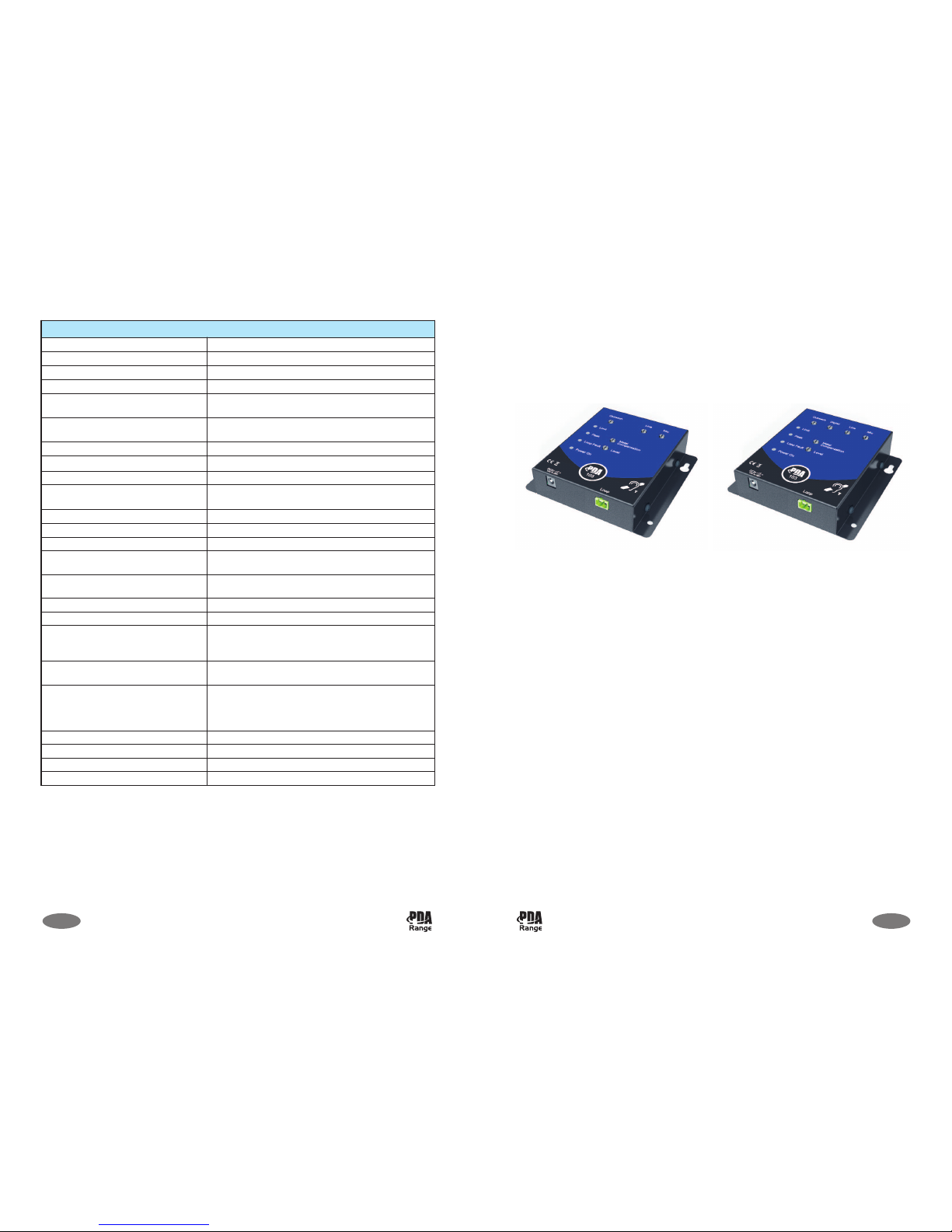
The PDA103 is a true current mode, hearing loop amplifier. It may be surface-mounted and is
designed to cover ticket counters up to 1.2m2(PDA103C kit version), or rooms up to 50m
2
(PDA103R/L/S kit versions).
Safety guidelines, important notes and product safety note............................................ 2
PDA103 kit contents ............................................................................................................... 3
Overview of the PDA103 hearing loop amplifier ............................................................ 4/5
Typical PDA103C 1.2m
2
counter hearing loop system .......................................................... 6
Typical PDA103R/L 50m
2
small room hearing loop systems ................................................. 7
Typical PDA103S 50m
2
domestic TV lounge hearing loop system ....................................... 8
Overview of the outreach plate audio extension system ................................................... 9
Mounting the amplifier ......................................................................................................... 9
System set-up and testing ................................................................................................. 10/11
PDA103 technical specification ............................................................................................. 12
INSTALLATION INSTRUCTIONS
This equipment must be installed by a suitably skilled and technically competent
person. Please read these instructions carefully before installation.
1 of 1212 of 12
PDA103 TECHNICAL SPECIFICATION
Rated supply voltage: 110 to 240Va.c. @ 50/60Hz
Rated power consumption: 18W PSU
Maximum RMS output current: 4A @ 1kHz
Maximum RMS load voltage: 5.5V
PDA103C approx. coverage area
using the TX2 pre-formed loop:
1.2m
2
PDA103R/L/S approx. coverage area
using 0.5mm2loop cable:
50m2, i.e. rooms up to approx. 7m x 7m
Recommended number of turns: Single turn
Recommended loop conductor size: 0.5mm2@ < 50m loop length
Frequency response -3dB: 120Hz to 5kHz as per BS EN 60118-4
Input signal level:
Mic: -60dB unbalanced; Line: -27dB stereo
unbalanced; Outreach: -10dB balanced.
Input impedance: Mic: 1k ohm; Line: 100k ohm; Outreach: 20k ohm.
Microphone phantom power: 12Vd.c.
Signal to noise ratio, A weighted: -62dB
Optical TOS-link receiver (PDA103S
kit only):
Up to 24 bit, 96kHz sampling
AGC range (3dB change in output
current), reference rated I/P voltage:
10dB
AGC ratio: 20:1
Amplifier mode: True current mode
Sensitivity level controls:
Mic, Line, Digital (PDA103S kit only), Outreach,
Metal Compensation, Level (all rotary pot controls
are screwdriver adjustable).
LED indicators:
Limit (Red), Peak (Red), Loop Fault (Red), Power On
(Green).
Connectors:
Mic (3.5mm mono jack socket); Line (3.5mm stereo
jack socket); Digital (PDA103S kit only); Outreach
(4-way pluggable screw terminal); DC in; Loop (2way pluggable screw terminal).
Dimensions (H x W x D): 35mm x 135mm x 130mm (including controls)
Weight: 380g (amplifier only)
IP Rating (to EN 60529): IP40
Operating temperature: 00C to 400C
PDA103 Installation Instructions Approved Document No. DAU0000103 Rev 4
© Errors and omissions excepted. No responsibility can be accepted by the manufacturer or distributors of this equipment for any
misinterpretation of this instruction, or for the compliance of the system as a whole. The manufacturers policy is one of continuous
improvement and we reserve the right to make changes to product specifications at our discretion and without prior notice.
PDA103S
Kit Version
PDA103C/R/L
Kit Version
PDA103 Installation Instructions Approved Document No. DAU0000103 Rev 4
SAFETY GUIDELINES
The PDA103 amplifier must be sited indoors and MUST NOT be subjected to conditions likely
to affect its performance.
DO NOT dismantle or attempt to modify the amplifier, there are no user-serviceable fuses or
parts inside the amplifier. For repair, contact your supplier.
WARNING: The surface of this unit may become hot during continued use.
2 of 12
M
ic
Line
Digital
Outreach
Limit
Peak
Level
Metal
Compensation
Additional testing
Hearing loop systems require careful testing and calibration prior to operation.
BS EN 60118-4 recommends that the achievable magnetic field strength of a hearing loop
system over a ‘covered area’ should be 400mA RMS per metre.
The most efficient way of ensuring this requirement is met is to test and set-up the system
using an FPROK hearing loop test kit. This kit includes a handheld Fosmeter Pro 400mA
magnetic field strength meter and a loop listener (for measuring background noise,
frequency response and metal compensation). Contact your supplier for more information.
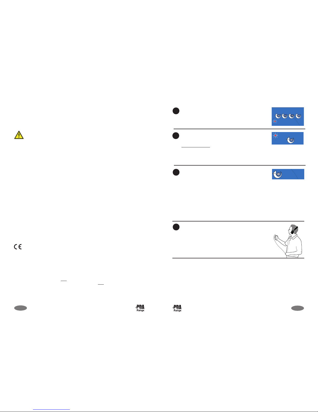
With the relevant audio input source(s) active, turn the
appropriate Outreach/Digital/Line/Mic level control(s)
clockwise until the red Limit indicator is flashing occasionally.
Turn the Level control clockwise until the red Peak indicator
just lights during periods of high signal level, i.e. when the
red Limit indicator just lights.
Product Safety Note
:
If the system is set up so that the Peak indicator is
permanently lit, the audio sound quality will be distorted and
the amplifier may shut down to protect it from overheating.
If high metal content is present in, or near, the hearing
loop, the sound heard by the loop listening device may be
‘woolly’ or ‘dull’. To rectify, turn the Metal Compensation
control clockwise in small increments until a natural balance
is achieved.
Note 1: If high metal content is present, the amplifier’s area
of coverage will be reduced, and further reduced, as the
Metal Compensation control is turned clockwise.
Note 2: If the Peak indicator lights strongly, turn the Level
control anti-clockwise and then adjust the Metal
Compensation control. You may have to adjust both these
controls several times to achieve most favourable operation.
Using an hearing loop test receiver, listen to the loop signal
in all areas where coverage is required (we recommend you
use a Fosmeter Pro for this purpose, see Additional Testing
below). If the signal level is not acceptable, adjust the Level
control in small increments until it is.
8
9
10
11
11 of 12
PRODUCT SAFETY NOTE
For safety reasons, the amplifier may shut down to protect it from overheating if too much
current passes through its sensitive protection circuitry. This may occur, for example, when the
Peak indicator remains permanently lit (see Page 11, Step 9).
IMPORTANT NOTES
These instructions are general and cannot be considered to cover every aspect of hearing loop
system design and installation.
We recommend you read BS 7594 - Code of practice for audio-frequency induction-loop
systems (AFILS) and BS EN 60118-4 - Induction loop systems for hearing aid purposes. Other
national standards of design/installation/commissioning should be referenced where pertinent.
This product has been manufactured in conformance with the requirements of all
applicable EU directives.
Equipment guarantee
This equipment is not guaranteed unless the system is installed and commissioned in accordance
with regional or national standards by an approved and competent person or organisation.
1
) Read these instructions.
2
) Keep these instructions.
3) Heed all warnings.
4) Follow all instructions.
5) WARNING: To reduce the risk of fire or electric shock, do not expose this apparatus to rain or moisture.
6) Clean only with dry cloth.
7) Do not block any ventilation openings. Install in accordance with the manufacturer's instructions.
8) Do not install near any heat sources such as radiators, heat registers, stoves, or other apparatus (including
amplifiers) that produce heat.
9) Protect the power cord from being walked on or pinched particularly at plugs, convenience receptacles,
and the point where they exit from the apparatus.
10) Only use attachments/accessories specified by the manufacturer.
11) Unplug this apparatus during lightning storms or when unused for long periods of time.
12) Refer all servicing to qualified service personnel. Servicing is required when the apparatus has been
damaged in any way, such as power-supply cord or plug is damaged, liquid has been spilled or objects
have fallen into the apparatus, the apparatus has been exposed to rain or moisture, does not operate
normally, or has been dropped.
PDA103 Installation Instructions Approved Document No. DAU0000103 Rev 4
PDA103 Installation Instructions Approved Document No. DAU0000103 Rev 4
 Loading...