

PDA103
HEARING LOOP AMPLIFIER
The PDA103 is a true current mode, hearing loop amplifier. It may be surface-mounted and is
designed to cover ticket counters up to 1.2m2(PDA103C kit version), or rooms up to 50m
2
(PDA103R/L/S kit versions).
Safety guidelines, important notes and product safety note............................................ 2
PDA103 kit contents ............................................................................................................... 3
Overview of the PDA103 hearing loop amplifier ............................................................ 4/5
Typical PDA103C 1.2m
2
counter hearing loop system .......................................................... 6
Typical PDA103R/L 50m
2
small room hearing loop systems ................................................. 7
Typical PDA103S 50m
2
domestic TV lounge hearing loop system ....................................... 8
Overview of the outreach plate audio extension system ................................................... 9
Mounting the amplifier ......................................................................................................... 9
System set-up and testing ................................................................................................. 10/11
PDA103 technical specification ............................................................................................. 12
INSTALLATION INSTRUCTIONS
This equipment must be installed by a suitably skilled and technically competent
person. Please read these instructions carefully before installation.
1 of 1212 of 12
PDA103 TECHNICAL SPECIFICATION
Rated supply voltage: 110 to 240Va.c. @ 50/60Hz
Rated power consumption: 18W PSU
Maximum RMS output current: 4A @ 1kHz
Maximum RMS load voltage: 5.5V
PDA103C approx. coverage area
using the TX2 pre-formed loop:
1.2m
2
PDA103R/L/S approx. coverage area
using 0.5mm2loop cable:
50m2, i.e. rooms up to approx. 7m x 7m
Recommended number of turns: Single turn
Recommended loop conductor size: 0.5mm2@ < 50m loop length
Frequency response -3dB: 120Hz to 5kHz as per BS EN 60118-4
Input signal level:
Mic: -60dB unbalanced; Line: -27dB stereo
unbalanced; Outreach: -10dB balanced.
Input impedance: Mic: 1k ohm; Line: 100k ohm; Outreach: 20k ohm.
Microphone phantom power: 12Vd.c.
Signal to noise ratio, A weighted: -62dB
Optical TOS-link receiver (PDA103S
kit only):
Up to 24 bit, 96kHz sampling
AGC range (3dB change in output
current), reference rated I/P voltage:
10dB
AGC ratio: 20:1
Amplifier mode: True current mode
Sensitivity level controls:
Mic, Line, Digital (PDA103S kit only), Outreach,
Metal Compensation, Level (all rotary pot controls
are screwdriver adjustable).
LED indicators:
Limit (Red), Peak (Red), Loop Fault (Red), Power On
(Green).
Connectors:
Mic (3.5mm mono jack socket); Line (3.5mm stereo
jack socket); Digital (PDA103S kit only); Outreach
(4-way pluggable screw terminal); DC in; Loop (2way pluggable screw terminal).
Dimensions (H x W x D): 35mm x 135mm x 130mm (including controls)
Weight: 380g (amplifier only)
IP Rating (to EN 60529): IP40
Operating temperature: 00C to 400C
PDA103 Installation Instructions Approved Document No. DAU0000103 Rev 4
© Errors and omissions excepted. No responsibility can be accepted by the manufacturer or distributors of this equipment for any
misinterpretation of this instruction, or for the compliance of the system as a whole. The manufacturers policy is one of continuous
improvement and we reserve the right to make changes to product specifications at our discretion and without prior notice.
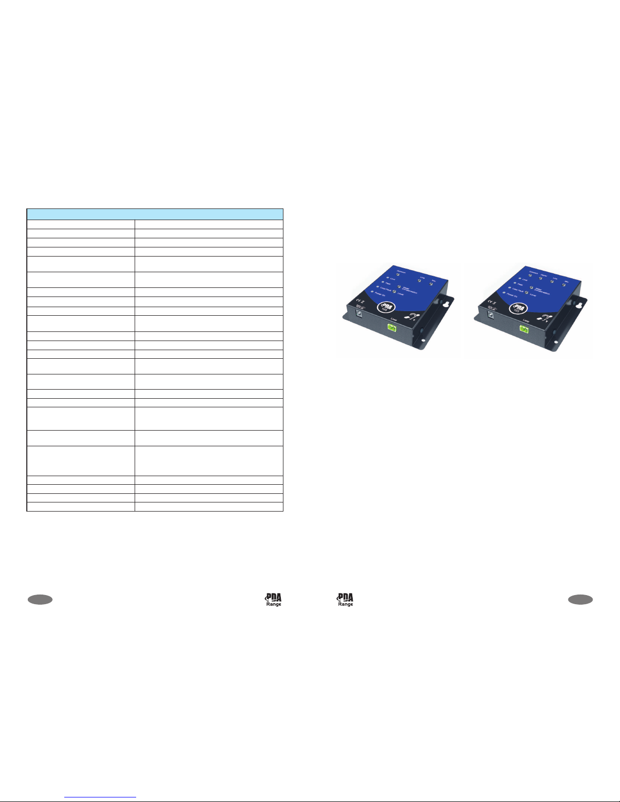
PDA103S
Kit Version
PDA103C/R/L
Kit Version
PDA103 Installation Instructions Approved Document No. DAU0000103 Rev 4
SAFETY GUIDELINES
The PDA103 amplifier must be sited indoors and MUST NOT be subjected to conditions likely
to affect its performance.
DO NOT dismantle or attempt to modify the amplifier, there are no user-serviceable fuses or
parts inside the amplifier. For repair, contact your supplier.
WARNING: The surface of this unit may become hot during continued use.
2 of 12
M
ic
Line
Digital
Outreach
Limit
Peak
Level
Metal
Compensation
Additional testing
Hearing loop systems require careful testing and calibration prior to operation.
BS EN 60118-4 recommends that the achievable magnetic field strength of a hearing loop
system over a ‘covered area’ should be 400mA RMS per metre.
The most efficient way of ensuring this requirement is met is to test and set-up the system
using an FPROK hearing loop test kit. This kit includes a handheld Fosmeter Pro 400mA
magnetic field strength meter and a loop listener (for measuring background noise,
frequency response and metal compensation). Contact your supplier for more information.
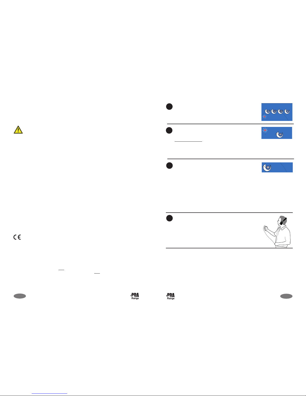
With the relevant audio input source(s) active, turn the
appropriate Outreach/Digital/Line/Mic level control(s)
clockwise until the red Limit indicator is flashing occasionally.
Turn the Level control clockwise until the red Peak indicator
just lights during periods of high signal level, i.e. when the
red Limit indicator just lights.
Product Safety Note
:
If the system is set up so that the Peak indicator is
permanently lit, the audio sound quality will be distorted and
the amplifier may shut down to protect it from overheating.
If high metal content is present in, or near, the hearing
loop, the sound heard by the loop listening device may be
‘woolly’ or ‘dull’. To rectify, turn the Metal Compensation
control clockwise in small increments until a natural balance
is achieved.
Note 1: If high metal content is present, the amplifier’s area
of coverage will be reduced, and further reduced, as the
Metal Compensation control is turned clockwise.
Note 2: If the Peak indicator lights strongly, turn the Level
control anti-clockwise and then adjust the Metal
Compensation control. You may have to adjust both these
controls several times to achieve most favourable operation.
Using an hearing loop test receiver, listen to the loop signal
in all areas where coverage is required (we recommend you
use a Fosmeter Pro for this purpose, see Additional Testing
below). If the signal level is not acceptable, adjust the Level
control in small increments until it is.
8
9
10
11
11 of 12
PRODUCT SAFETY NOTE
For safety reasons, the amplifier may shut down to protect it from overheating if too much
current passes through its sensitive protection circuitry. This may occur, for example, when the
Peak indicator remains permanently lit (see Page 11, Step 9).
IMPORTANT NOTES
These instructions are general and cannot be considered to cover every aspect of hearing loop
system design and installation.
We recommend you read BS 7594 - Code of practice for audio-frequency induction-loop
systems (AFILS) and BS EN 60118-4 - Induction loop systems for hearing aid purposes. Other
national standards of design/installation/commissioning should be referenced where pertinent.
This product has been manufactured in conformance with the requirements of all
applicable EU directives.
Equipment guarantee
This equipment is not guaranteed unless the system is installed and commissioned in accordance
with regional or national standards by an approved and competent person or organisation.
1
) Read these instructions.
2
) Keep these instructions.
3) Heed all warnings.
4) Follow all instructions.
5) WARNING: To reduce the risk of fire or electric shock, do not expose this apparatus to rain or moisture.
6) Clean only with dry cloth.
7) Do not block any ventilation openings. Install in accordance with the manufacturer's instructions.
8) Do not install near any heat sources such as radiators, heat registers, stoves, or other apparatus (including
amplifiers) that produce heat.
9) Protect the power cord from being walked on or pinched particularly at plugs, convenience receptacles,
and the point where they exit from the apparatus.
10) Only use attachments/accessories specified by the manufacturer.
11) Unplug this apparatus during lightning storms or when unused for long periods of time.
12) Refer all servicing to qualified service personnel. Servicing is required when the apparatus has been
damaged in any way, such as power-supply cord or plug is damaged, liquid has been spilled or objects
have fallen into the apparatus, the apparatus has been exposed to rain or moisture, does not operate
normally, or has been dropped.
PDA103 Installation Instructions Approved Document No. DAU0000103 Rev 4
PDA103 Installation Instructions Approved Document No. DAU0000103 Rev 4

L
o
o
p
+
-
M
i
c
L
i
n
e
D
i
g
i
t
a
l
Mic
Line
Digital
Outreach
Level
Metal
Compensation
D
C
i
n
1
IMPORTANT: DO NOT power up the system before completing Step 7 below.
The amplifier MUST NOT be operated without a loop connected to it.
Install the loop cable.
BEFORE connecting the loop to the amplifier, use a multimeter to check the loop is not
shorted to ground at any point. It WILL damage the amplifier if it is.
Connect the loop cable (supplied) to the amplifier.
Remove approx. 6mm of the outer insulation from each end
of the loop cable, then secure both ends to the screw
terminals of the 2-way loop cable connector (supplied). Next,
plug the 2-way connector to the amplifier’s Loop connector.
If relevant, plug the AMT microphone, or an alternative
electret microphone, into the amplifier’s Mic connector.
If relevant, plug the audio line level into the amplifier’s Line
input, or TOS-link connector cable (not supplied) into the
amplifier’s Digital connector.
Ensure the amplifier’s Outreach, Digital, Line, Mic, Metal
Compensation and Level pot controls are set to minimum by
turning them fully anti-clockwise.
SYSTEM SET-UP AND TESTING
2
3
4
6
7
10 of 12
O
u
t
r
e
a
c
h
A
+
A
-
V+
GND
If relevant, connect the outreach system to the amplifier.
Remove approx. 6mm of the outer insulation from all cable
ends, then secure the ends to the screw terminals of the 4way outreach connector (supplied). Next, plug the 4-way
connector into the amplifier’s Outreach connector.
5
PDA103 KIT CONTENTS
The PDA103 hearing loop amplifier is available in the following kits.
PDA103C - 1.2m2Counter Hearing Loop Kit:
1 x PDA103 hearing loop amplifier
1 x 230Va.c. PL1/PSU1 plug-top power supply
1 x TX2 pre-formed counter loop cable and fixings
1 x AMT tie/desk microphone c/w 1.5m lead and attachments
1 x Accessory pack containing the installation instructions (this document), four cable ties,
four self-adhesive cable tie bases, one 4-way ‘outreach’ connector, one 2-way loop cable
connector, one ‘hearing loop fitted’ sticker.
PDA103R - 50m2Small Room Hearing Loop Kit (plated mic version):
1 x PDA103 hearing loop amplifier
1 x 230Va.c. PL1/PSU1 plug-top power supply
1 x APM ‘outreach’ plated microphone c/w 6m Belden cable
1 x 40m of 0.5mm
2
loop cable
1 x Accessory pack (as per the PDA103C kit).
PDA103L - 50m2Small Room Hearing Loop Kit (tie/desk mic version):
1 x PDA103 hearing loop amplifier
1 x 230Va.c. PL1/PSU1 plug-top power supply
1 x AMT tie/desk microphone c/w 1.5m lead and attachments
1 x 40m of 0.5mm
2
loop cable
1 x Accessory pack (as per the PDA103C kit).
PDA103S - 50m2Domestic TV Lounge Hearing Loop Kit:
1 x PDA103 hearing loop amplifier (with TOS-link digital connector)
1 x 230Va.c. PL1/PSU1 plug-top power supply
1 x APL dual phono line level ‘outreach’ plate c/w 6m Belden cable
1 x APS SCART to dual phono connection lead
1 x 40m of 0.5mm2loop cable
1 x Accessory pack (as per the PDA103C kit).
3 of 12
PDA103 Installation Instructions Approved Document No. DAU0000103 Rev 4
PDA103 Installation Instructions Approved Document No. DAU0000103 Rev 4
Connect the plug-top power supply (supplied) to the AC
mains socket and then to the amplifier’s DC in connector.
Ensure the amplifier’s green Power On indicator lights.

General operation
The amplifier mixes and amplifies the microphone, line, digital (PDA103S kit only) and
outreach input signals and feeds them through its sophisticated automatic gain control (AGC)
circuitry before outputting them to the hearing loop.
OVERVIEW OF THE PDA103 HEARING LOOP AMPLIFIER
103
Loop
DCin
+
-
14V to 20V
MicLine
Digital
Outreach
Power On
Loop Fault
Peak
Limit
Level
Metal
Compensation
Loop
Output
DC in
+
-
4 of 12
A +A -V+GND
O
utreach
Digital
Input
Line
I
nput
Mic
I
nput
9
10
11
12
7
8
14
13
15 16
Connectors, controls and indicators
Below is a overview of the PDA103’s connectors, pot level controls and LED indicators.
N
ot
e
: T
he
digit
a
l input
(3
) a
nd digit
a
l c
ont
r
ol (6
) s
how
n in t
he
dia
gr
a
ms
be
low
only
a
pply
t
o
t
he
a
mplif
ie
r
s
upplie
d w
it
h t
he
P
D
A
1
0
3
S
k
it
w
hic
h ha
s
a
T
O
S
-link
digit
a
l c
onne
c
t
or
.
The PDA103 is fully compatible with the
outreach plate audio input extension
system. This system allows the connection
of multiple microphones, or line level
inputs via a range of specially designed
wall, ceiling or desk-mountable single
gang plates.
Up to ten outreach plates (any mix) can
be daisychained to the amplifier’s
‘outreach’ connector (supplied) with
cable lengths up to 100m (total network
length) easily achievable using standard
two pair audio cable such as Belden 8723
- see typical wiring diagrams.
Contact your supplier for more
information.
PDA103
4-WAY OUTREACH
CONNECTOR
A +
A -
V+
GND
OUTREACH PLATE
AUDIO INPUT
A OUT +
A OUT -
A
IN +
A IN -
V+
GND
GREEN (A+)
WHITE (A-)
RED (V+)
B
LACK (GND)
OUTREACH PLATE
AUDIO INPUT
A OUT +
A OUT -
A
IN +
A IN -
V+
GND
GREEN (A+)
WHITE (A-)
RED (V+)
BLACK (GND)
A
B
D
C
E
F
A
B
D
C
E
F
MULTIPLE OUTREACH PLATE WIRING CONNECTIONS
TO NEXT
OUTREACH
PLATE
9 of 12
MOUNTING THE AMPLIFIER
The amplifier can be surface-mounted in
any orientation, provided the controls are
accessible and indicators clearly visible.
Surface-mounting
Using mounting screws (not supplied) fix
the amplifier securely to a wall, desk or
side of counter, as appropriate. Always
assess the condition and construction of
the mounting surface prior to installation
and use suitable screw fixings (No. 8-10,
or 4-5mm screws).
95mm
120mm
5mm (x4)
Surface-mounting
fixing details
5
6
1
2 4
3
PDA103
4-WAY OUTREACH
CONNECTOR
A
B
C
D
E
F
SINGLE OUTREACH PLATE
W
IRING CONNECTIONS
e
.g. APL / APM Outreach Plate
A OUT-
A OUT+
V+
GND
A+
A-
V
+
GND
A
F
E
B
C
D
RED (V+)
G
REEN (A OUT+)
W
HITE (A OUT-)
B
LACK (GND)
N
OT USED
NOT USED
G
REEN (A+)
BLACK (GND)
RED (V+)
GREEN (A+)
WHITE (A-)
RED (V+)
BLACK (GND)
WHITE (A-)
A
IN+
A IN-
OVERVIEW OF THE OUTREACH PLATE AUDIO EXTENSION SYSTEM
PDA103 Installation Instructions Approved Document No. DAU0000103 Rev 4
PDA103 Installation Instructions Approved Document No. DAU0000103 Rev 4

8 of 12
103
L
oop
DCin
+
-
1
4V to 20V
MicLine
D
igitalOutreach
Power On
L
oop Fault
Peak
L
imit
Level
Metal
Compensation
TYPICAL PDA103S 50m2DOMESTIC TV LOUNGE HEARING LOOP SYSTEM
4
3
1
PDA103S Kit Components
1 Loop fitted sticker:
Position the sticker where it can be clearly seen by hearing
aid users.
2
APL dual phono line
level ‘outreach’ plate
c/w APS SCART lead &
Belden connection cable:
Surface-mount the APL plate onto a standard 25mm UK
back box - a 6m length of Belden cable is provided for
connecting the APL to the amplifier. The APS SCART lead
(supplied), should be connected to the audio source
(normally a TV) and the APL plate.
3 Amplifier location:
The amplifier should be surface-mounted and sited as close
as possible to the equipment to which it is connected.
4 Loop cable:
Run the loop cable horizontally around the perimeter of
the room. For best results, tuck the cable under the edge
of the carpet or fixed to skirting boards or the ceiling.
If installing a floor loop, ensure the loop cable is protected
from being crushed in walkways or by furniture.
2
Note: As an alternative to using the APL plate, the amplifier supplied with the PDA103S kit
has a TOS-link digital connector and most modern televisions can be directly connected to
the amplifier using a TOS-link cable (not supplied).
Inputs & Input Controls
1 Mic input:
3.5mm mono jack input supplied with 12V phantom power
for use with electret microphones. Note that dynamic
microphones are NOT compatible with this input.
8 Mic control: Adjusts the sensitivity of microphone level input.
2 Line input: 3.5mm stereo jack input for connecting an audio (line) source.
7 Line control: Adjusts the sensitivity of the audio line level input.
3 Digital input: TOS-link digital input (PDA103S kit only).
6 Digital control: Adjusts the sensitivity of the TOS-link input (PDA103S kit only).
4 Outreach input: 4-way input for the outreach plate audio input system.
5 Outreach control: Adjusts the sensitivity of the outreach input.
15 DC in:
2.5mm DC power supply connector. Only connect the supplied
plug-top power supply to the amplifier.
Indicators
9 Limit: Lights red to confirm the AGC circuitry is functioning.
10 Peak: Lights red in line with peaks in the input signal(s).
11 Loop Fault:
Lights red when the hearing loop is unintentionally connected
to an input ground. To rectify, turn off the AC mains and
check for loop wiring faults before reapplying power.
12 Power On: Lights green when the amplifier is receiving power.
Outputs & Output Controls
16 Loop output: 2-way loop connection.
13
Metal Compensation
control:
In applications with high metal content, this control can be
used to help combat the frequency response problems caused
by metal ‘absorbing’ the magnetic field.
14 Level control:
Adjusts the strength of the magnetic field generated by the
hearing loop.
5 of 12
PDA103 Installation Instructions Approved Document No. DAU0000103 Rev 4
PDA103 Installation Instructions Approved Document No. DAU0000103 Rev 4

If multiple counter loops are
required in close proximity, it
is possible that the ‘field’
generated by one system may
be picked up by a person who
is standing at the next. Adjust
the field strength and loop
shape to avoid this.
TYPICAL PDA103C 1.2m2COUNTER HEARING LOOP SYSTEM
MULTIPLE
COUNTER LOOPS
PDA103C Kit Components
1
Loop fitted
sticker:
Position the sticker where it can be clearly seen by hearing aid users.
2
AMT tie/desk
microphone
c/w 1.5m lead:
Position the mic as close as possible to mouth height using the selfadhesive pad (supplied). For best results position it no nearer than
300mm and no further than 1.2m distance from the operator’s
mouth. Avoid mounting it near sources of unwanted noise, e.g. a
cooling fan, or a telephone.
3 Loop cable:
Fix the pre-formed TX2 counter loop (supplied) to the underside of
the counter, desk or table.
For best results in counter applications:
Bend the opened out ‘squared’ loop at a right angle half way down
its length. Secure half the square to the underside of the desk and
run the other half down the inside of the back vertical surface.
For best results in desk/table applications:
Secure the opened out ‘squared’ loop to the underside of the table
at the end nearest to the hearing aid user. Another option is to fit
the loop above a suspended ceiling. Again, position the loop so that
it is central to where the hearing aid user would naturally stand.
4
Amplifier
location:
Mount the amplifier to the side of the counter using suitable screws.
3
1
4
2
6 of 12
TYPICAL PDA103R 50m2SMALL ROOM HEARING LOOP SYSTEM (plated mic version)
2
1
4
3
PDA103R / PDA103L Kit Components
1
Loop fitted
sticker:
Position the sticker where it can be clearly seen by hearing aid users.
2
APM ‘outreach’
plated microphone
c/w Belden
connection cable:
For best results it should be mounted on a standard 25mm back
box, ideally on a suspended ceiling height of 2.5 to 3m although it
can also be surface-mounted. If mounting the microphone at
ceiling height, avoid positioning it too close to ventilators, or air
conditioning ducts. 6m of Belden cable is included for connecting
the APM to the amplifier.
3 Loop cable:
Run the loop cable horizontally around the perimeter of the room,
ideally located at ceiling height (e.g. above a suspended ceiling) or
tucked under the edge of a carpet, or fixed to skirting boards.
If installing a floor loop, ensure the loop cable is protected from
being crushed in walkways, or by furniture.
4 Amplifier location:
Surface-mount the amplifier using suitable mounting screws.
PDA103R only: To avoid unsightly connection leads, the amplifier
may be mounted above a suspended ceiling, particularly if a
ceiling loop is fitted to reduce wiring runs.
5
AMT tie/desk
microphone c/w
1.5m lead:
Position the microphone as close as possible to the user using the
self-adhesive pad (supplied). For best results position it no nearer
than 300mm and no further than 1.2m distance from the
operator’s mouth. Avoid mounting it near sources of unwanted
noise, e.g. a cooling fan, or a telephone.
7 of 12
TYPICAL PDA103L 50m2SMALL ROOM HEARING LOOP SYSTEM (tie/desk mic version)
4
3
1
5
PDA103 Installation Instructions Approved Document No. DAU0000103 Rev 4
PDA103 Installation Instructions Approved Document No. DAU0000103 Rev 4
 Loading...