

PC Vision Ultra Matrix Pro 8N, Ultra Matrix Pro 12A, Ultra Matrix Pro 16M User Manual
1
Ultra Matrix-Pro Series Product
User’s Manual

2
Copyright
No part of this manual, including the products and software described in it, may be reproduced,
transmitted, transcribed, stored in a retrieval system, or translated into any language in any form
or by any means, except documentation kept by the purchaser for backup purposes, without the
express written permission of PC Vision Limited.
PC Vision provides this manual “as it” without warranty of any kind, either express or implied,
including but not limited to the implied warranties or conditions of merchantability or fitness for a
particular purpose. In no event shall PC Vision or its employees held liable for any indirect, special,
incidental, or consequential damages (including damages for loss of data, loss of profits,
interruption of business and the like).
Product warranty or service will not be extended if:
1. The product is repaired, modified or altered, unless such repair, modification of alteration is
authorized in writing by PC Vision.
2. The serial number of the product is defaced or missing.
All brand names, logos and registered trademarks mentioned are property of its respective owners.
The manual may not have the latest specifications and drivers. Please log onto the PC Vision website
or contact us for the latest information.
© 2015 PC VISION. All rights reserved
Product Name: PC VISION Ultra Matrix-Pro Series
Manual Version: v1.3
Release Date: September 2015
PC VISION
PC Vision Limited. (Greater China)
Address: 11th Floor, No. 70, Sec. 1, Cheng Teh Road, Taipei
Tel: (886) 02-2555-2578
Fax: (886) 02-2558-7287
Global Website: www.pcvision.com.hk
3
Preface
This guide is intended to be used as a step-by-step instruction for installation, and as a reference for
operating, troubleshooting and upgrade.
Note
Please log onto the website for the latest drivers and information.
Website: http://www.pcvision.com.hk/
Before you start
In order to avoid product damage and ensure your personal safety, please be sure to read the
instructions and safety guide in detail before operation. Refer to the “Advisories” section in the
Preface for advisory conventions used in this user’s guide, including the distinction between
Warnings, Cautions, Important Notes, and Notes.
Handle/Operate the PC with great care. Only qualified, experienced and authorized maintenance crews
should perform internal and external maintenance on the PC. High voltage and power can cause
personal injuries if serviced without proper precautions.
Install/Remove components with great care. Please refer to the installation instructions and
precautions in the user’s manual. Please contact PC Vision Technical Support with any questions.
Access should only be granted to service personnel or users instructed about the restrictions applied to
the location and any precautions that need to be taken. Access is provided through the use of a tool,
lock and key, or other means of security, and is maintained by authorized personnel responsible for the
location.
Caution
When the power cable is connected to the power socket, there is live high voltage current in the
PC. Power off the system and remove the power cable before removing the case cover. Turning
off the system power switch does not remove power to the components.

4
Table of Contents
1). Introduction ......................................................................... 5
PACKAGE CONTENTS ..................................................................................................... 5
SYSTEM VIEW ............................................................................................................. 6
Front I/O panel ............................................................................................................................................................. 6
Rear I/ O panel .............................................................................................................................................................. 7
2). Quick Installation ............................................................... 11
ULTRA MATRIX-PRO SERIES PRODUCT CONNECTION CONFIGURATION INSTRUCTIONS ................ 11
3). Setting ............................................................................... 13
HARDWARE SETTINGS ................................................................................................. 13
Configuring the BIOS................................................................................................................................................ 13
ENTER WINDOWS OS ................................................................................................. 14
Install UMCC ................................................................................................................................................................ 14
UMCC Device link ...................................................................................................................................................... 16
Display Parameter ..................................................................................................................................................... 22
SETTING MULTI-SCREEN SPLICING DRIVER ....................................................................... 27
Introduction of AMD graphics driver settings (twelve control panel splicing) ...................................... 27
Introduction of NVIDIA graphics driver settings (eight control panels splicing) ................................... 31
Resolutions List: ...................................................................... 37
Horizontal / Vertical Parameters List: ...................................... 37
5
1). Introduction
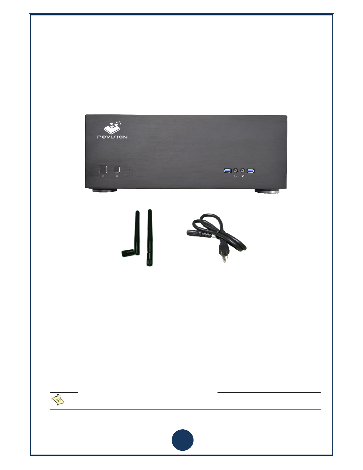
Package contents
Please check for the following components:
1 x Ultra Matrix-Pro series system
2 x Wi-Fi Antennas
1 x Power Cord Cable
(Please refer to the shipment documents for the actual products)
1. Optional items are not included in the package contents.
2. If any of the package contents are damaged, please contact your dealer immediately.
6
System View
Please refer to the following diagram to determine the components of the system.
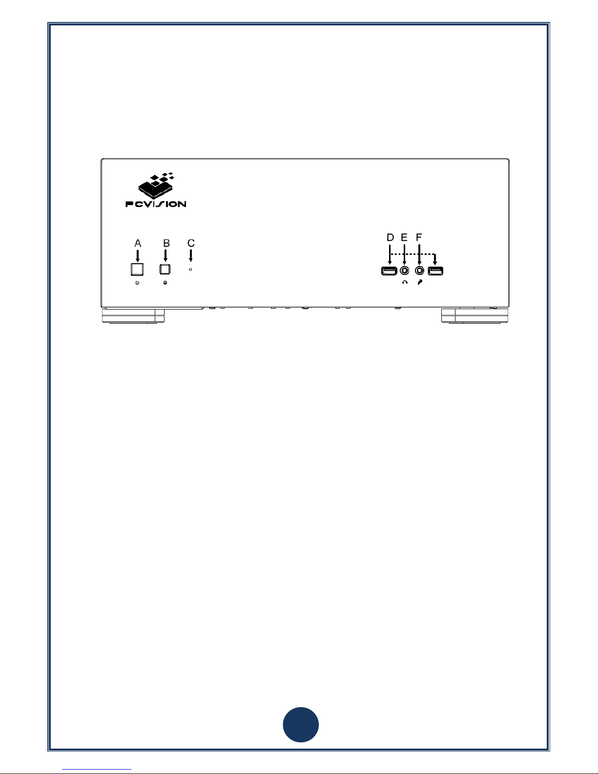
Front I/O panel
Picture 1: Diagram of front I/O
A. Power button
The power button turns the system ON and OFF.
B. Reset button
The reset button is used to hard reset the system quickly.
C. Power status indicator
The power LED is on when the system is on.
D. USB 3.0 ports
The USB 3.0 ports support SuperSpeed USB 3.0 devices (5 Gb/s data transfer rate) and is backwards
compatible with USB 2.0/1.1/1.0 devices.
E. Headphone jack
The stereo headphone jack is used to connect the system’s audio out signal to amplified speakers or
headphones.
F. Microphone jack
The microphone input is designed to connect a microphone for video conferencing, voice narrations or simple
audio recordings.
7
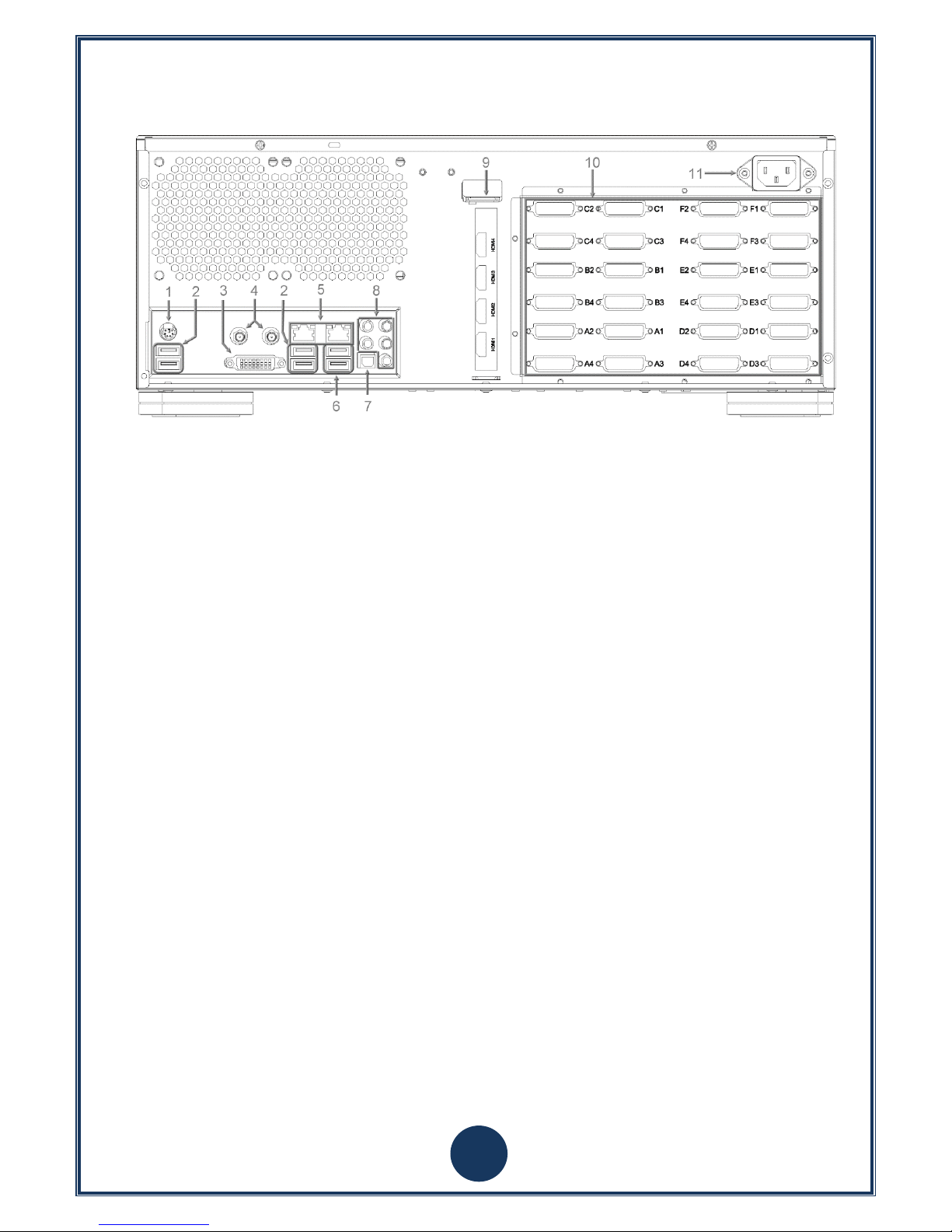
Rear I/ O panel
Picture 2: Diagram of rear I/O
1. PS/2 Keyboard/Mouse port
2. USB 3.0 ports
3. DVI-I output
4. Wi-Fi/Bluetooth antenna connectors
5. Gigabit Ethernet ports
6. USB 2.0 ports
7. Optical S/PDIF output
8. Audio ports
9. Video inputs
10. DVI-D outputs
11. Power connector
PS/2 Keyboard/Mouse Port
PS/2 interface is used to connect keyboard and mouse via Y Cable. (The purple interface is for keyboard, and
the green one is for mouse.)
USB 3.0 ports
The USB 3.0 ports support the SuperSpeed USB 3.0 devices (data transfer rate: 5 Gb/s) and are backwards
compatible with USB 2.0/1.1/1.0 devices.
DVI-I port
The DVI-I output supports connection to DVI-I high definition displays.
DVI-D ports
The DVI-D port supports connection to DVI-D high definition displays. Due to the different models, the
amount of DVI-D outputs may vary (Please refer to the shipment information for actual product). Connect
the DVI cable from the system to a monitor for display output. (Note: please refer to Ultra Matrix-Pro series
product connection configuration instructions)
Power socket
Connect the attached power cable to AC adapter and the socket. To avoid damage to the power supply and
PC, please use the included power cable.
8
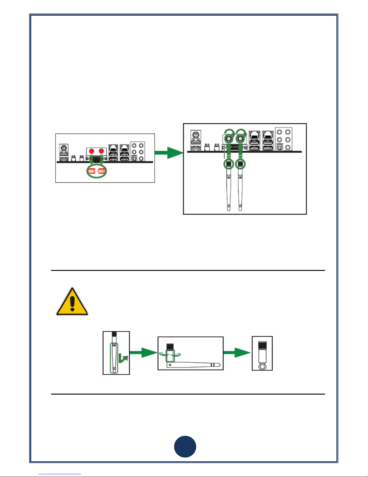
Wi-Fi/Bluetooth antenna connectors
This motherboard supports two antennas for WiFi/BT combo. Please refer to the following to install the WiFi/BT antennas.
Step 1. Remove the red caps from the Wi-Fi/BT antenna connectors.
Step 2. Attach the antennas to the Wi-Fi/BT antenna connectors and rotate in a clockwise direction until its
secure.
Note
1. Please note the appearance of the Wi-Fi/BT antennas may differ from those shown in
this manual.
2. Users must install Wi-Fi/BT antennas for better signal reception.
3. Users can adjust the Wi-Fi/BT antennas to the best receiving direction as shown below.
Gigabit Ethernet
The eight-pin RJ-45 LAN port supports standard CAT5/6 Ethernet cables for connection to local area networks
(LAN) with speeds up to 10/100/1000Mbps.
9
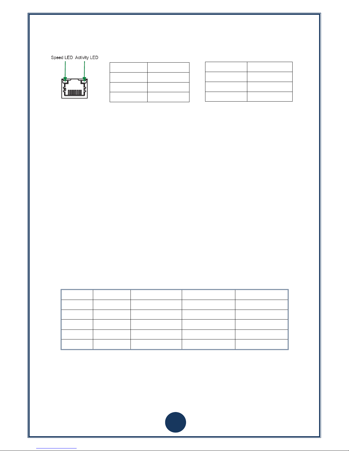
LAN port LED indicators
USB 2.0 ports
The USB (Universal Serial Bus) port is compatible with USB devices such as keyboards, mice, cameras and
hard disk drives. (480 Mb/s transfer rate)
Optical S/PDIF output
The optical S/PDIF output is used to connect the system to digital audio receivers or speakers.
Audio ports
Line-out
Stereo output jack is used to connect an analogue audio output signal to a stereo receiver or headphones.
Microphone input
The microphone input is designed to connect a microphone for video conferencing, voice narrations or simple
audio recordings.
Line-in
The Line-in jack accepts inputs from unamplified stereo audio signals.
Port
2-Channel
4-Channel
6-Channel
8-Channel
Blue
Line-in
Line-in
Line-in
Side speaker out
Green
Line-out
Front speaker out
Front speaker out
Front speaker out
Pink
Mic-in
Mic-in
Mic-in
Mic-in
Black
- - Center/Subwoofer
Center/Subwoofer
Orange
-
Rear speaker out
Rear speaker out
Rear speaker out
Video inputs (optional)
Provide two or four sets of video and audio input signal via HDMI a SDI connections.
There are two different video input cards available with HDMI or SDI inputs.
Activity LED
Status
Description
Off
No link
Orange
Linked
Blinking
Data activity
Speed LED
Status
Description
Off
10 Mbps
Green
100 Mbps
Orange
1000 Mbps

10
Product model: PCVision N2 4K PCIe Capture
Port
Mode 1
Mode 2
Port 1
1920x1080P@60fps
0
Port 2
1920x1080P@60fps
3840x2160@30fps
(HDMI interface) (SDI interface)
Product model: PCVision N4 FHD PCIe Capture
Port
Mode 1
Mode 2
Port 1
1920x1080P@30fps
0
Port 2
1920x1080P@30fps
1920x1080P@60fps
Port 3
1920x1080P@30fps
0
Port 4
1920x1080P@30fps
1920x1080P@60fps
(HDMI interface) (SDI interface)
11
2). Quick Installation
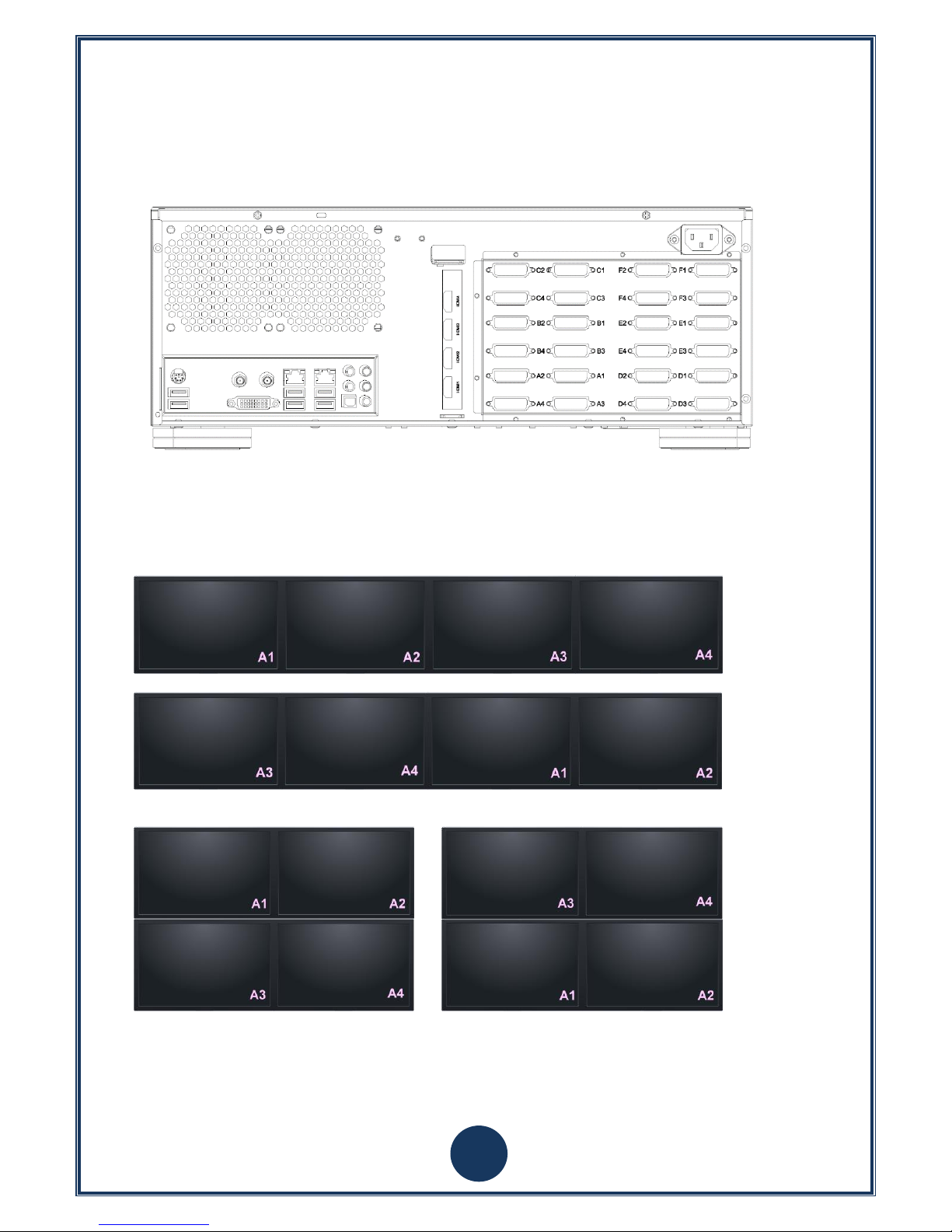
Ultra Matrix-Pro Series Product Connection Configuration Instructions
Diagram of DVI outputs in Ultra Matrix-Pro series product:
The DVI outputs of this product is divided into six groups: A~F. One group has four outputs according to displays 1~4. In
each group, display 1 and 2 are a pair, and 3 and 4 are pair.
Users can combine the monitors in a combination of 1x4 or 2x2
Diagram of 1x4 displays with DVI outputs:
or
Diagram of 2x3 displays with DVI outputs:
or
12
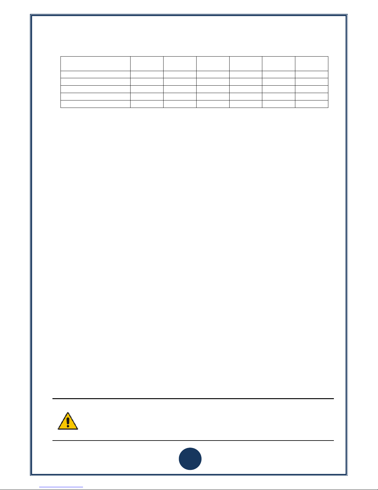
The distribution list of Ultra Matrix-Pro series product into each group output as following:
Ultra Matrix-Pro serial DVI
output number
Group A
Group B
Group C
Group D
Group E
Group F
8 ports
V V 12 ports
V V V 16 ports
V V V V
20 ports
V V V V V 24 ports
V V V V V
V
Note
Please check the marked No. on Ultra Matrix-Pro series products according to the above list, and
connect the output to the display. Because there are two displays in one group, display 1 and 2
cannot be interchanged, 3 and 4 cannot either.
Users can arrange the A~F groups via the graphics card driver settings.
 Loading...