

PCTEL GPS-TMG-HR-26N Installation Instructions Manual
GPS HR Antenna and Mount Kits Installation Instructions
Read these instructions thoroughly before assembly. Follow the
sequence for proper assembly and operation.
NOTICE
The installation, maintenance, or removal of antenna systems requires
qualied, experienced personnel. Antenna systems should be inspected
once a year by qualied personnel to verify proper installation,
maintenance, and condition of equipment.
ANTENNA DESCRIPTIONS
GPS-TMG-HR-26N is a self contained GPS antenna and mount kit. The
kit includes a right hand circularly polarized antenna that incorporates a
26 dB high performance, high out-of-band rejection, narrow band ampli-
er. It also includes mounting hardware to attach the antenna to a vertical
pipe within a range of diameters. See Mounting Pipe Diameters for
each kit.
GPS-TMG-HR-40N is a self contained GPS antenna and mount kit. The
kit includes a right hand circularly polarized antenna that incorporates a
40 dB high performance, high out-of-band rejection, narrow band ampli-
er. It also includes mounting hardware to attach the antenna to a vertical
pipe within a range of diameters. See Mounting Pipe Diameters for
each kit.
Note: A +5 volt dc bias is required for each of the active antennas and is
fed via the center conductor to provide power for the integrated low noise
preamplier. The voltage should already be present.
Range of Mounting Pipe Diameters for L-Bracket Mount Kit
The L-Bracket Mount Kit attaches the GPS antenna onto a customersupplied vertical pipe with a diameter ranging from 1.05” (26.7 mm) to
1.9” (48.3 mm). Standard 3/4”, 1”, 1-1/4”, and 1-1/2” pipe (which has
an outside diameter of 1.05” (26.7 mm), 1.315” (33.4 mm), 1.66” (42.2
mm), and 1.9” (48.3 mm) respectively can be used.
MOUNTING KIT DESCRIPTIONS
The Standard Mount Kit includes the Collar Bracket Mount Kit and the
L-Bracket Mount Kit. Depending on your requirements, you can use
these kits together or separately. Keep remaining materials for future use.
Collar Bracket Mount Kit - Part # GPS-TMG-MNT-R
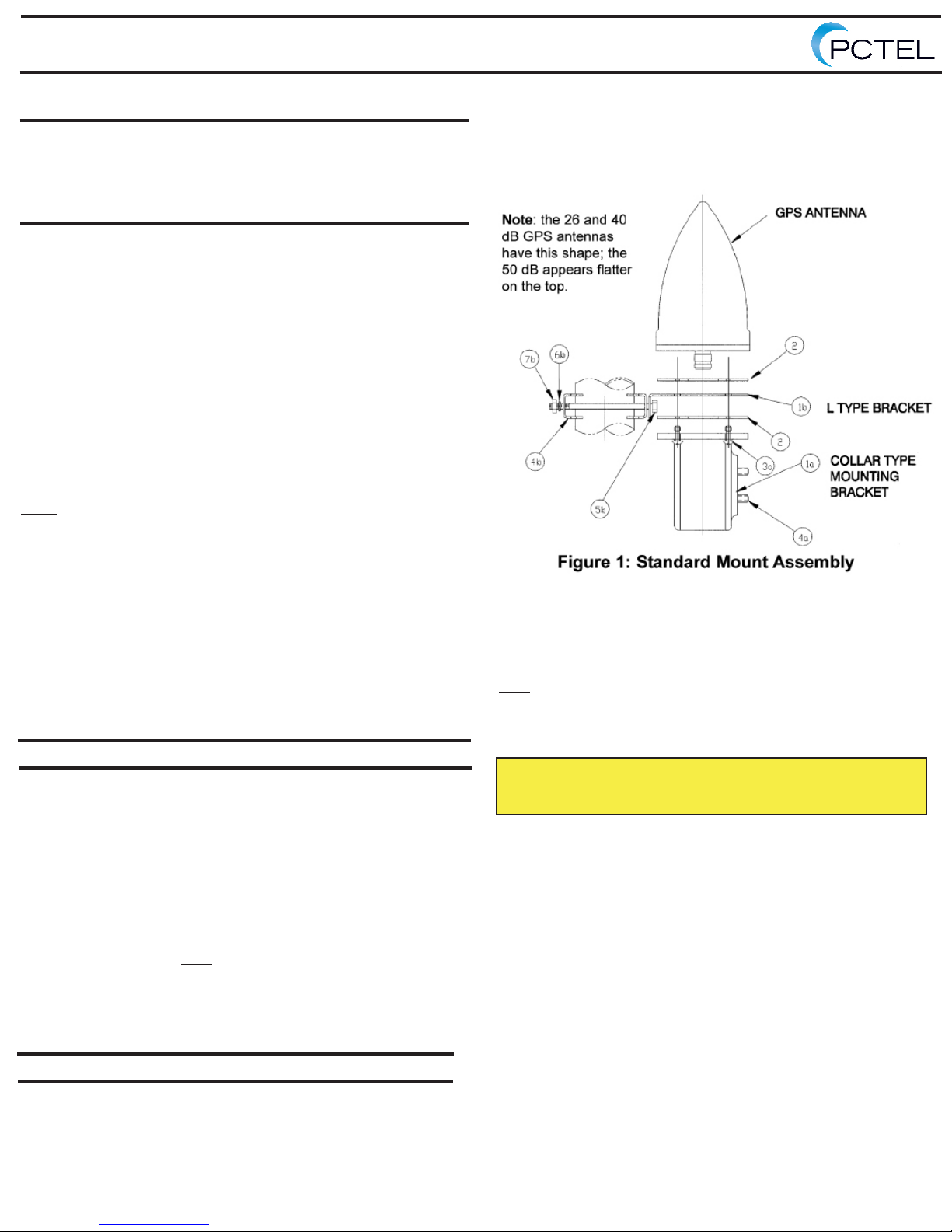
Refer to Figure 1. The Collar Bracket Mount Kit includes these parts:
Item # Quantity Description
1a 1 Collar
2 1 Gasket
3a 4 M5 Mounting Screw
4a 2 0.25”-20 UNC-3A x 1.0 set screw
5a 1 Allen wrench
Range of Mounting Pipe Diameters for Collar Bracket Mount Kit
The Collar Bracket Mount Kit attaches the GPS antenna onto a
customer-supplied vertical pipe with a diameter ranging from 1.05”
(26.7 mm) to 1.315” (33.4 mm). Standard 3/4” and 1” pipe (which has
an outside diameter of 1.05” (26.7 mm) and 1.315 (33.4 mm),
respectively can be used. Note: The Collar Bracket Mount attaches to the
top of the customer-supplied vertical pipe. Cable installation is through
the internal diameter of the pipe.
L-Bracket Mounting Kit - Part # GPS-TMG-LMMT
Refer to Figure 1. The L-Bracket Mount Kit includes these parts:
Item # Quantity Description
1b 1 L-Bracket
2 1 Gasket
3b 4 M5 Mounting Screw
4b 2 Cleat
5b 2 0.25”-20 UNC x 3.5” hex head cap screw
6b 2 0.25” lock washer
7b 2 0.25”-20 UNC hex nut
TOOLS REQUIRED FOR INSTALLATION
(1) Phillips cross-head screwdriver. #2
(2) 7/16” open end wrenches
INSTALLING THE STANDARD MOUNT KIT
Note: The Standard Mount Kit contains 2 mounting bracket types. The
two brackets can be used together, as the Standard Mount Kit shown
in Figure 1, separately as the Collar Bracket Mount Kit shown in Figure
2, or separately as the L-Bracket Mount Kit shown in Figure 3.
**NOTE: This antenna contains precision electronic equipment.
Installers must observe precautions for handling electrostatic
sensitive devices.**
Refer to Figure 1.
1 Before you begin, be sure that the mounting pipe is the correct
diameter and free of any components from previous installations.
2 Attach the L-bracket (1b) to the customer-supplied vertical mounting
pipe using bolts (4b, 5b, 6b, and 7b). Locate in the desired position.
3 Tighten 0.25” hardware.
4 Insert the cable assembly, tted with N male connector, through the
collar (1a) and gasket (2). Install captive screws (3a). Do not install
set screws (4a) for this conguration.
5 With the gasket (2) on top of the L-bracket, insert the cable assem-
bly through the L-bracket and gasket. Attach the cable assembly to the
GPS antenna and tighten the connector as required.
6 Slide the collar and gasket up to the antenna and attach the anten-
na by pushing the four captive screws through the gaskets and tighten
them into the antenna base.
7 Install the weatherproong (not provided with the Standard Mount
Kit) that extends from directly underneath the ange on the collar
bracket to at least 3” below the bottom of the collar measured on the
cable assembly. The unused set screw holes are covered.
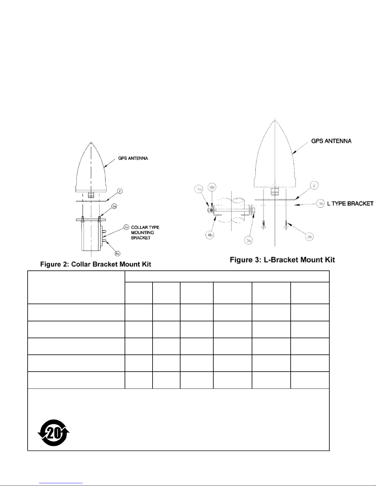
INSTALLING THE COLLAR BRACKET MOUNT KIT
O O O O O O
X O O O O O
X O O O O O
O O O O O O
X O O O O O
Refer to Figure 2.
1 Install captive screws (3a) and set screws (4a) in collar (1a), then
push captive screws (3a) through gasket (2) holes in order to retain the
gasket.
2 Insert the cable assembly, tted with N male connector, through the
customer-supplied vertical mounting pipe, and collar and gasket assembly previously prepared.
3 Attach the cable assembly to the GPS antenna and tighten the con-
nector as required.
4 Attach the collar and gasket assembly to the antenna and tighten the
captive screws (3a) into the antenna base.
5 Slide the assembly down so that the collar slides over the mounting
pipe. Tighten the set screws (4a).
6 Install weatherproong (not included with the Collar Bracket Mount
Kit) that extends from directly underneath the ange on the collar
bracket to at least 3” below the bottom of the collar measured on the
cable assembly.
INSTALLING THE L-BRACKET MOUNT KIT
1 Attach the L-bracket (1b) to the customer-supplied vertical pipe
using bolts 4b, 5b, 6b and 7b. Locate in the desired position.
2 Tighten 0.25” hardware.
3 With a gasket (2) on top of the L-bracket, insert the cable assem-
bly through the L-bracket and gasket. Attach the cable assembly to
the GPS antenna and tighten the connector as required.
4 Insert the four short screws (3b) through the L-bracket and gasket
and attach the antennas and tighten the screws. Do not use captive
screws for this conguration.
5 Install weatherproong (not provided with the L-Bracket Mount
Kit) that extends at least 2” below the bottom of the connector on the
cable assembly to directly underneath the base plate of the antenna.
有毒有害物质或元素部件名称
铅
(Pb) 汞(Hg) 镉(Cd)
六价铬
(Cr6+)
多溴联苯
(PBB)
多溴二苯醚
(PBDE)
天线塑料零件
ANTENNA PLASTIC PARTS
天线金属零件
ANTENNA METAL PARTS
电缆装置
CABLE ASSEMBLY
固定架塑料零件
MOUNT ASSEMBLY PLASTIC PARTS
固定架金属零件
MOUNT ASSEMBLY METAL PARTS
O:表示该有毒有害物质在该部件所有均质材料中的含量均在SJ/T 11363-2006 标准规定的限量要求以下。
X:表示该有毒有害物质至少在该部件的某一均质材料中的含量超出SJ/T11363-2006 标准规定的限量要求。
这张表意欲只联络服从与中国要求; 它不意欲联络服从与欧共体RoHS 任何其它环境要求.
PCTEL, Inc. Tel. +630-372-6800
471 Brighton Drive Fax +630-372-8077
Bloomingdale, IL 60108 Web: http://www.antenna.com MIS-TIMING Rev B
 Loading...