

PCS Ferguson 8000 Series Manual

The 8000 Series® brand is trademarked by PCS Ferguson®.
These documents and materials are copyrighted by PCS Ferguson.
© 2017 All rights reserved.
Single Well Plunger Lift Controller Manual
For information contact:
PCS Ferguson
3771 Eureka Way
Frederick, CO 80516
Phone: 720-407-3550
Fax: 720-407-3540
Email: information@pcsferguson.com
Website: www.doverals.com/pcsferguson
1

Single Well Plunger Lift Controller Manual
1 Contents
1 Understanding Plunger Lift
Operations .......................................................8
1.1 Components ..........................................................8
1.2 Plunger Lift Cycle .....................................................10
1.2.1 Basic Modes of the Plunger Cycle ................................................10
1.2.2 Conditional Modes of the Plunger Cycle ...........................................10
1.3 Optimization Programs, Production Methods, and Set
Points ..............................................................11
1.4 Time Method ........................................................12
1.4.1 Time Set Points and the Basic Plunger Cycle ........................................12
1.4.2 Pressure Set Points and the Time Method ..........................................13
1.4.3 Other Conditional Modes and Set Points ...........................................13
1.5 Pressure Methods ....................................................14
1.6 Automatic Adjustment for Plunger Arrival ...................................15
1.6.1 AutoCycle Program ...........................................................15
1.6.2 Plunger Arrival Windows .......................................................16
1.6.3 Plunger Arrival Counts. . . . . . . . . . . . . . . . . . . . . . . . . . . . . . . . . . . . . . . . . . . . . . . . . . . . . . . . .19
1.6.4 Automatic Time Adjustments ....................................................22
1.6.5 AutoCycle Pressure Set Points ...................................................23
1.6.6 Automatic Adjustment of Pressure Set Points .......................................24
2 Set Points for Plunger Lift
Operations ......................................................26
2.1 Control Production Modes ..............................................26
2.1.1 Fall Time (All Production Methods) ...............................................27
2.1.2 Close Time (All Production Methods) ..............................................27
2.1.3 A Open Time (All Production Methods) .............................................28
2.1.4 Sales Time (All Production Methods) ..............................................28
2.1.5 Delay Close Time (Pressure methods) .............................................28
2.1.6 Mandatory Shut-In Time (All Production Methods) ....................................29
2.1.7 Casing Peak Pressure Time (Pressure methods) .....................................29
2.1.8 High Line Pressure Shut-In Delay (All Production Methods) .............................30
2

Single Well Plunger Lift Controller Manual
2.1.9 B Open Time (All Production Methods) ............................................30
2.1.10 B Delay Time (All Production Methods) ...........................................31
2.1.11 Differential Open Pressure (Pressure methods) .....................................31
2.1.12 Load Factor (Fluid Slug) (Pressure methods) .......................................31
2.1.13 Casing Drop Pressure (Pressure Methods). . . . . . . . . . . . . . . . . . . . . . . . . . . . . . . . . . . . . . . . .33
2.2 Control Exit of SALES Mode (Pressure Methods Only) ..........................34
2.2.1 D.I.P. Close Pressure (Pressure Methods) ..........................................35
2.2.2 Gas Low Flow Close Rate (Pressure Methods) .......................................35
2.2.3 Critical Flow Constant (Pressure Methods) .........................................35
2.3 Control Shut-In .......................................................36
2.3.1 Low Line Pressure (All Production Methods) ........................................36
2.3.2 High Line Pressure (All Production Methods) ........................................36
3 Set Points for the AutoCycle™
Program ........................................................37
3.1 Overview of Arrival Windows ............................................37
3.1.1 Reset Defaults Button .........................................................38
3.2 Early Window Area ....................................................38
3.2.1 Enable Early Arrival Option .....................................................38
3.2.2 Hr Min Sec in the Early Window area. . . . . . . . . . . . . . . . . . . . . . . . . . . . . . . . . . . . . . . . . . . . . .38
3.2.3 Initial Count in the Early Window area .............................................38
3.2.4 Current Count in the Early Window area ...........................................39
3.3 Fast Window Area .....................................................39
3.3.1 (Fast Plunger Time) (Hr Min Sec) .................................................39
3.3.2 Initial in the Fast Window area ..................................................39
3.3.3 Current in the Fast Window area .................................................40
3.3.4 History (Read Only) ...........................................................40
3.3.5 Deduct from Off-Time in Fast Window .............................................40
3.3.6 Add to Afterflow in Fast Window area .............................................40
3.4 Good Window Area ....................................................41
3.4.1 No Label (Hr Min Sec) .........................................................41
3.4.2 Initial in the Good Window area ..................................................41
3.4.3 Current in the Good Window area ................................................41
3.4.4 (History Read Only) ..........................................................42
3.4.5 Current Afterflow in the Good Window area .........................................42
3

Single Well Plunger Lift Controller Manual
3.4.6 Current Off-Time .............................................................42
3.4.7 Min Off-Time ...............................................................43
3.4.8 Min Afterflow ...............................................................43
3.4.9 Max Afterflow ...............................................................43
3.5 Slow Window Area ....................................................44
3.5.1 Current On-Time .............................................................44
3.5.2 Initial in the Slow Window area ..................................................44
3.5.3 Current in the Slow Window area ................................................44
3.5.4 (History Read-Only) ..........................................................45
3.5.5 Deduct from Afterflow in Slow Window ............................................45
3.5.6 Add to Off-Time .............................................................45
3.6 No Plunger Area ......................................................46
3.6.1 Initial in the No Plunger area ....................................................46
3.6.2 Current in the No Plunger area ..................................................46
3.6.3 (History Read-Only) ...........................................................46
3.6.4 Add to Off-Time in the No Plunger area ............................................46
3.6.5 Max Off-Time in the No Plunger Area .............................................46
3.7 Pressure Overrides ....................................................47
3.7.1 Open Tubing Valve (Production Valve) If Area ........................................47
3.7.2 Close Tubing Valve (A Valve) If Area ...............................................47
3.7.3 Plunger Open Adjustments .....................................................48
3.7.4 Plunger Close Adjustments Area .................................................48
3.7.5 Safety Shut-Down (PSIG) Area. . . . . . . . . . . . . . . . . . . . . . . . . . . . . . . . . . . . . . . . . . . . . . . . . . .49
3.8 Controls for Operations .................................................49
3.8.1 Options for controlling adjustments ...............................................49
3.9 Activity History (Read-only) ..............................................49
4 8000 Series Walkup Display and Keypad Commands ...................50
4.1 Basic Key Sequences ..................................................50
4.2 The Single-Well™ Application Keypad Commands .............................52
4.3 The AutoCycle™ Program Keypad Commands
(Single-Well only) ........................................................53
5 Understanding Well Site
Communications .................................................56
4

Single Well Plunger Lift Controller Manual
5.1 On Site Communication with an 8000 Series Controller ........................56
5.2 Off Site Communication with an 8000 Series Controller ........................57
5.3 Well Networks .......................................................58
5.3.1 Well System Components ......................................................58
5.3.2 The 8000 Series Controllers on a Well Network ......................................58
5.3.3 Wireless Communications ......................................................59
5.3.4 Wired Communications ........................................................60
5.4 Security Access Codes .................................................60
6 Monitoring Tank Levels ..........................................62
6.1 Understanding the Tank Management System ...............................62
6.1.1 System Settings .............................................................62
6.1.2 Tank Settings ...............................................................63
6.1.3 Alarms and Shut-Ins ..........................................................64
6.1.4 Polling Interval ..............................................................65
6.1.5 The Tank Configuration File .....................................................65
6.2 Preparation .........................................................66
6.3 Task List for Tank Management ..........................................66
6.4 Configure Tanks ......................................................66
6.4.1 Importing an OleumTech or iLevel Tank configuration file ..............................67
6.4.2 Configuring Tanks in the WellVision Application ......................................67
6.5 Tank System Configuration ..............................................69
6.6 Monitoring Levels in the Tanks ...........................................70
6.6.1 Review Current Status ........................................................70
6.6.2 Review Tank Trends ..........................................................71
6.6.3 Respond to Tank Level Alarms. . . . . . . . . . . . . . . . . . . . . . . . . . . . . . . . . . . . . . . . . . . . . . . . . . .74
7 Viewing Graphs of Well
Performance ....................................................76
7.1 Preparation .........................................................76
7.2 General Task List .....................................................76
7.3 View a Basic Well Trending Graph .........................................77
7.4 View a Summary of Data within a Timeframe ................................79
7.5 View Details and Calculations within a Timeframe ............................80
5

Single Well Plunger Lift Controller Manual
Appendix A: Single Well I/O Worksheet ................................83
Appendix B: 8000 Series® Agency Approval ............................84
6

Single Well Plunger Lift Controller Manual
Revision History
Date Description Version
6/1/2017 Initial Release 1.0
7

Single Well Plunger Lift Controller Manual
1 Understanding Plunger Lift
Operations
Over time, a well’s gas production declines but a plunger lift system can increase a well’s
productivity and life span. The natural pressure that lifts the gas from the well to the surface
declines. Liquids collect in the wellbore or tubing and reduce the gas ow. If the liquids remain
in the well, they eventually stop the gas ow. A plunger system lifts the liquids out of the well.
Deliquication optimizes gas production and increases the life span of the well.
This chapter describes basic components of a plunger lift system, plunger lift functions, and your
role in the operations. For more information about conguring a well program.
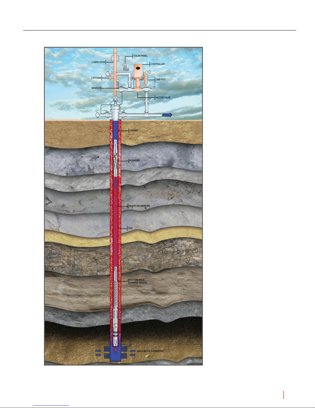
1.1 Components
The well system components of plunger lift operations are:
Plunger Components
• Plunger that acts as a well-bore swab
• Lubricator that catches the plunger when it surfaces and provides access for maintenance
• Arrival sensor that indicates when the plunger has surfaced
• Bottom hole bumper spring that cushions the plunger’s fall
Plunger Cycle Control
• Motor valve, a pneumatic valve, that controls gas ow
• Production valve , a solenoid valve, that controls the motor valve
• Controller that uses a Well Program to control the production valve
• User interface such as the WellVision™ application, the WellTrekker™ application, or the Walk
Up Display to direct the controller
– Analog and digital devices that provide data inputs the controller monitors
– Sales line pressure sensor
– Tubing pressure sensor
– Casing pressure sensor
– Other devices
• [Optional] Tank valve a solenoid valve for a vent that can relieve backpressure on the Sales Line
and assist the plunger cycle
Production on Site (provided by the site owner)
• Sales line
• Separator that separates gas, oil, and water
• Tank that stores the liquids removed by the plunger
8
Understanding Plunger Lift Operations
Single Well Plunger Lift Controller Manual
Figure 1.1 The basic components of the Plunger Lift System in place
Understanding Plunger Lift Operations
9

Single Well Plunger Lift Controller Manual
1.2 Plunger Lift Cycle
The plunger system lifts the liquids using pressure from the gas ow. The plunger moves between
the bottom hole bumper spring and the lubricator at the top of the well. The Motor Valve controls
physical ow of the gas. The production valve controls when the Motor Valve is open and closed.
When the production valve is closed, the gas ow is off. The plunger falls down the well, through
the liquid, and to the bottom hole bumper spring. When the production valve is open, the gas
ow is on. The natural pressure from the gas ow lifts the plunger. The liquids move ahead of the
plunger, out of the well, and into a separator or directly into the tanks. The separator directs gas into
the Sales line, oil to an oil tank, and water to a water tank.
The controller uses a Well Program to direct the components through the plunger cycle. The plunger
cycle has modes. The Well Program species the modes used during the cycle. Using the Well
Program, the controller optimizes production in response to the well conditions. The Well Program
has production methods to simplify conguration of optimization. The user chooses a production
method and enters set points to create a Well Program.
The following paragraphs describe the modes and production methods that the Well Program uses
to optimize production.
1.2.1 Basic Modes of the Plunger Cycle
The plunger cycle has basic modes: FALL, CLOSE, A OPEN, and SALES. During FALL mode, the
plunger returns to the bottom of the well. During CLOSE mode, the pressures build in the well. The
well is not producing gas. During A OPEN mode, the plunger rises to the top with the liquids. After
the plunger arrives, the Well Program uses SALES mode to produce gas.
The modes that the Well Program uses depend on the arrival of the plunger, on the production
method, and set points. An arrival sensor detects the surfacing of the plunger. The controller
monitors this sensor and other input devices. The controller compares the data inputs with the set
points specied by the user in the Well Program. In the basic scenario for the Time method, after
the plunger arrives, the controller directs the Well Program into SALES mode.
Each mode has primary set points and a group of secondary set points. The basic set points are
periods of time or pressure values. Additional set points are values used in a calculation. The
production method determines which set points the Well Program uses to exit and enter modes.
For a basic example, the primary set points for the Time Method are Fall Time, Close Time, A Open
Time, and Sales Time.
1.2.2 Conditional Modes of the Plunger Cycle
The controller and Well Program can respond automatically to well conditions. The well conditions
affect the arrival of the plunger. A Well Program has a group of secondary set points that specify
conditional modes: Line Delay, Mandatory Shut-In, B Open, and B Delay. These set points allow the
plunger lift system to respond to the conditions of the well. The production method species which
set points the controller uses to respond to well conditions.
To optimize production in response to well conditions, the Well Program has modes for using delay,
shut-in, and the Tank Valve. Not all well systems have a Tank Valve, but a Well Program can use it to
optimize production.
For an example of a delay, the basic mode, A OPEN, is a xed time, A Open Time. However, well
conditions can slow the arrival of the plunger. If the Well Program species the set point, Delay
Close, the controller can allow production beyond the time set for A OPEN mode. The plunger does
not arrive but gas continues to ow and the plunger continues to rise.
To close production in response to conditions, the system has a MANDATORY SHUT-IN mode.
10
Understanding Plunger Lift Operations

Single Well Plunger Lift Controller Manual
The primary set point for this mode is a time setting. However, the controller can use a pressure
setting on the Casing to enter this mode. For example, if the plunger does not arrive during the time
specied for the set point, A Open, the controller counts down the time interval specied by the set
point and detects that the pressure on the casing is lower. After that time, the Well Program enters
Mandatory Shut-in mode and production stops so that pressure can build to raise the plunger on
the next plunger cycle.
1.3 Optimization Programs, Production Methods,
and Set Points
The user can specify a Well Program in the WellVision application. Using the information unique to
the well, the user chooses a production method and species the set points. The controller uses
this Well Program to evaluate the data inputs and direct operations.
The Well Program can include the following factors to adjust production. These factors apply to
every production method.
Constant factors
• Tubing depth
• Tubing diameter
• Plunger type or style
Variable factors
• Sales line pressure
• Production ratio of gas-to-liquid
Some set points are common to all of the methods. These set points close the well to protect the
gas lines from damage or can respond to possible damage.
For example, to monitor backpressure and protect the sales line, each method includes the
following set points for that line:
• High Line Shut-in Pressure: The maximum pressure that the program allows on the line before
automatically closing. To prevent shut-in due to momentary spikes in pressure, the user can
specify a delay time.
• High Line Pressure Shut-in Delay time: A period of time the controller samples the pressure.
The controller uses the samples to decide if a high reading is temporary or steady. If temporary,
production can continue. If steady, the program closes the well.
• Low Line Shut-in Pressure: The minimum pressure the program allows on the line before
automatically closing the well.
NOTE Best Practice Always enter values for these set points to protect the
Sales Line. These settings can prevent ruptures or close the well in the
case of a rupture. Also, set the Notifications tool to send a text or an
email in response to alarms. For more information about the Notifications
tool.
Understanding Plunger Lift Operations
11

Single Well Plunger Lift Controller Manual
The
user can choose from several production methods. Each method employs specic primary
set points and a group of associated set points. These set points allow the user to customize
movement between the modes in response to well conditions.
The user can disable any set point by entering zero or a value too high to occur. (Zero time is
00:00:00: zero pressure is 0: high time is 99:59:59: and high pressure depends on the gauge).
The WellVision and WellTrekker applications offer the following production methods to optimize a
well with the Plunger Lift System:
• Time method
• AutoCycle
• Casing pressure minus Tubing pressure
• Casing pressure minus Line pressure
• Tubing pressure minus Line pressure
The following paragraphs describe the methods and their set points.
™
1.4 Time Method
Using the Time method, the controller manages the well using set points of time. The times for
FALL, A OPEN, CLOSE, and SALES modes repeat for every plunger cycle. The Well Program
offers additional set points to respond to well conditions. The following sections describe how the
controller and the Well Program work together through the basic and conditional modes of the
plunger cycle.
1.4.1 Time Set Points and the Basic Plunger Cycle
A basic Well Program, that uses the time method, moves through the following modes using
plunger arrival and time countdowns.
The controller closes the production valve and the Well Program enters the FALL mode. During
FALL mode, the plunger drops. The controller counts down the time specied for Fall Time. The
Well Program enters CLOSE mode. The controller counts down the time specied for Close Time.
During the CLOSE mode, pressure builds in the well. The Controller monitors the data coming from
the pressure sensors. However, the Well Program using a Time method does not use pressure
readings to change modes. The controller continues to monitor pressures and the Well Program can
use pressure settings to override the time settings.
After the Close Time expires, the Well Program enters A OPEN mode and opens the production
valve. The controller counts down the time set in A Open Time. This setting should match the
time the plunger usually takes to come up the wellbore and remove the liquids. The arrival sensor
detects the surfacing of the plunger. The controller directs the Well Program to enter SALES mode.
The controller counts down the time set in Sales Time. After the Sales Time expires, the controller
directs the Well Program to enter FALL mode and closes the production valve. The process repeats.
If the Sales Time is zero (00:00:00), the Well Program enters FALL mode. The user can turn off any
set point for time with a value of zero (00:00:00).
1.4.2 Pressure Set Points and the Time Method
If the user species the set points for high and low line pressure, the Well Program responds to the
pressure settings by entering DELAY CLOSE mode. The sequence of the modes depends on when
12
Understanding Plunger Lift Operations

the controller detected the High Line Shut-In pressure and the results of the sampling during the
time set in High Line Pressure Shut-in Delay.
If the pressure sampling reveals the pressure temporarily spiked and then fell, the Well Program
returns to the previous mode. The controller continues to count down the time set for that mode
during the delay. The delay does not change the duration of A OPEN mode or SALES mode. If the
sampling reveals a possible problem, the Well Program closes the well and enters FALL mode.
Well conditions change and the changes affect the plunger arrival. To respond to variations in the
plunger’s arrival, the user can specify additional set points in the Well Program.
1.4.3 Other Conditional Modes and Set Points
The plunger might not surface as expected during A OPEN mode. The ow might be too low
to raise the plunger or excessive backpressure might be the issue. To raise the plunger, the
program must close the production valve for a time to build pressure or the system must relieve
excessive backpressure through a Tank valve.
Respond to no plunger by closing Production Valve
To close the production valve, the Well Program offers a set point, Mandatory Shut-in Time. After
the A Open time expires, the controller checks for data from the arrival sensor. If the controller
cannot verify arrival and the program provides a Mandatory Shut-In time, the controller directs
the program into MANDATORY mode and counts down the time. After the time expires, the Well
Program enters FALL mode.
Single Well Plunger Lift Controller Manual
Respond to no plunger by opening Tank Valve
If the system has a Tank valve, the controller can direct the valve to open and vent the
backpressure. With the backpressure relieved, the ow might raise the plunger and the sensor can
detect the arrival.
NOTE To add this response to the program, the user specifies a B Open Time.
After the plunger arrives and the time expires, the Well Program enters
B DELAY mode. The program uses the B Delay Time before entering
SALES mode. The controller counts down the Sales Time. The program
enters FALL mode. The cycle repeats.
If the ow cannot raise the plunger with the backpressure released, then the program enters
MANDATORY SHUT-IN mode. The controller counts down the Mandatory Shut-In time. When the
controller detects the required pressure, the program enters OPEN mode. The cycle repeats.
1.5 Pressure Methods
A well analysis might indicate that pressures instead of time would optimize production more
effectively. The user can choose a production method that uses pressure differentials. The
WellVision and WellTrekker applications offer the following calculations as methods.
• Casing pressure minus Tubing pressure
• Casing pressure minus Line pressure
• Tubing pressure minus Line pressure
Understanding Plunger Lift Operations
13

Single Well Plunger Lift Controller Manual
For each of these methods, the user species a differential in pressure based on the well’s
conditions. The primary set point is Differential Open Pressure. The set point answers the question:
“At what pressure difference, does the user want the Well Program to enter A OPEN mode?” Time
still plays a role as the controller counts down Fall Time before evaluating the pressure differential.
After the Fall Time expires, the controller evaluates the pressures. If the difference meets pressure
criteria specied by the set points shown as a delta p (∆p), then the Well Program enters A OPEN
mode.
Basis for differential Well opens if: Well example
Casing pressure–Line
pressure
Tubing pressure–Line
pressure
Casing Pressure–Tubing
pressure
Table 1.1 Production Methods and Pressure Differential
Difference in pressure is greater
than (>) the setting
Difference in pressure is greater
than (>) the setting
Difference in pressure is less than
(<) the setting
Most well configurations
Well with a packer and no annular
pressure
Well with slow building casing
pressures
NOTE For more information about the pressure methods, see “Configuring a
Single Well” section.
1.6 Automatic Adjustment for Plunger Arrival
The AutoCycle program provides automatic adjustments using the plunger arrival and number of
arrivals. Using the AutoCycle program, a Well Program uses initial settings, monitors the arrival
of the plunger, and adjusts time or pressure settings. These adjustments ne-tune the production
cycle for optimum plunger speed, liquid removal, and well performance.
For this method, the controller monitors and records data about the arrival of the plunger. The Well
Program uses the AutoCycle program to respond with adjustments immediately.
1.6.1 AutoCycle Program
The AutoCycle program uses the plunger speed to optimize production. The user provides values
for a set of arrival times. These values depend on the specic well. The arrival times indicate to the
AutoCycle program the speed of the plunger. Given the depth of the well and the arrival time, the
AutoCycle program calculates the speed by dividing the depth by the arrival time.
Maintaining an appropriate speed is critical to the production and safety of the well. Plungers that
arrive too fast can damage wellhead components at the surface. This damage might lead to failure.
Plungers that arrive too slowly might indicate that pressures are falling. The pressure might be
too low to raise the plunger. To optimize production, the AutoCycle program uses a set of arrival
windows. Each window type has a set of counters and a set of adjustments.
14
Understanding Plunger Lift Operations
The following gure shows the basic plunger cycle and where the AutoCycle program windows
affect production.
The following paragraphs provide more detail about the windows and their associated parameters.
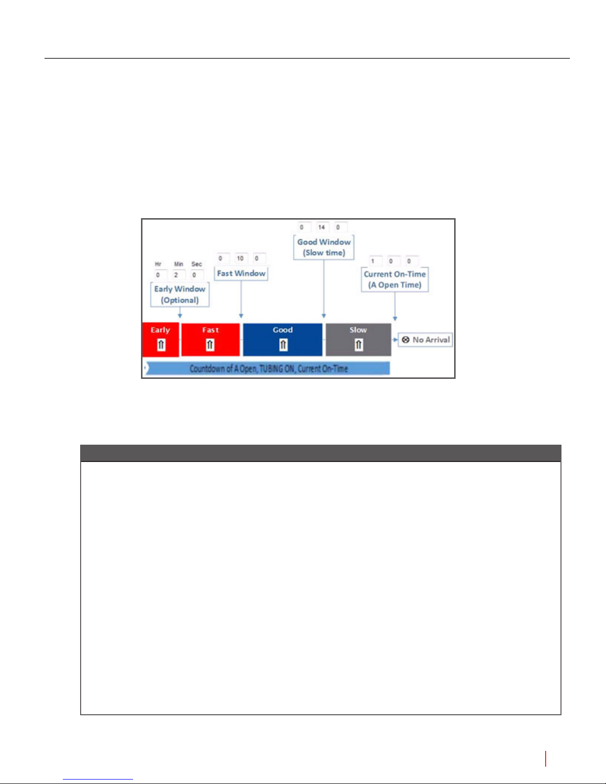
1.6.2 Plunger Arrival Windows
The AutoCycle program makes the same adjustments to the Afterow Time and Off Time that an
on-site operator would make while tending the well. The AutoCycle program compares the actual
time of arrival with the values of the set points for the windows.
Single Well Plunger Lift Controller Manual
Figure 1.2 Arrival Windows of the AutoCycle program
This comparison identies the speed of the plunger and the category of arrival. Using this
comparison, the AutoCycle program makes adjustments as described in the table below:
Plunger arrival Adjustments applied
Good None, within this window of time, the AutoCycle program does not make adjustments. However,
the program does identify minimum and maximum and maximum times. This arrival indicates
best production of the well with an ideal arrival time. The depth of well divided by 800 equals
the low limit of Good window. The depth of well divided by 600 equals the upper limit of Good
window.
Fast Decrease down hole pressure: within this window of time, the plunger arrives too quickly. The
AutoCycle program deducts from the Fall Time/Close Time (Off Time) and/or adds to the Sales
Time (Afterflow time).
Slow Increase down hole pressure: within this window of time, the plunger has arrived too slowly. This
indicates that the down hole pressure was too low. The AutoCycle program deducts from the
Sales Time (Afterflow time) and/or adds to the Fall Time/Close Time (Off Time). The user can set
options for No Afterflow on Slow Arrivals. The depth of well divided by 270 equals the upper limit
of slow window.
No Increase down hole pressure if the plunger fails to arrive at the surface. The AutoCycle program
deducts from the Sales Time (Afterflow time) and adds to the Fall Time/Close Time (Off Time).
No arrival might indicate well problems. If the plunger fails to arrive multiple times, The AutoCycle
program informs the controller: the Well Program enters FALL mode and the well is shut-in. The
controller raises a Plunger Error. The user needs to clear the error before production can resume.
Table 1.2 AutoCycle Plunger Arrival Window Definitions
Understanding Plunger Lift Operations
15
Single Well Plunger Lift Controller Manual
The user provides set points for times typical to the well. These set points dene the windows
of time so that the AutoCycle program can adjust the settings correctly. The arrival windows are
dependent on the amount of time it takes for the plunger to reach the surface after the production
valve (Tubing Valve) is open.
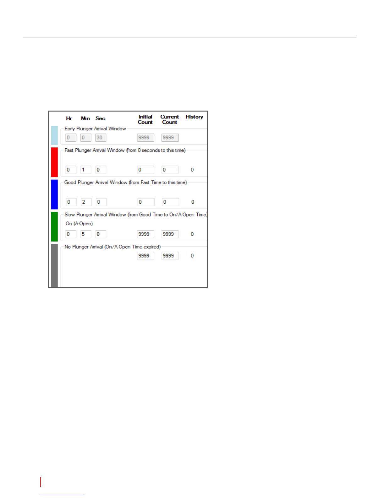
The gure below shows the area of the AutoCycle tab that species the values for evaluating
plunger speed.
Figure 1.3 The set points in the Arrival Windows area on the AutoCycle program tab
The user provides the values for the plunger arrival times. The arrival time indicates the rate of
speed. If the user knows the depth of the well, the user can specify the well information for the
AutoCycle program. Given the depth of the well and the arrival time, the AutoCycle program
calculates the speed by dividing the depth by the arrival time. (Distance/Time = Speed) Maintaining
an appropriate speed is critical to the production and safety of the well.
16
Understanding Plunger Lift Operations
Single Well Plunger Lift Controller Manual
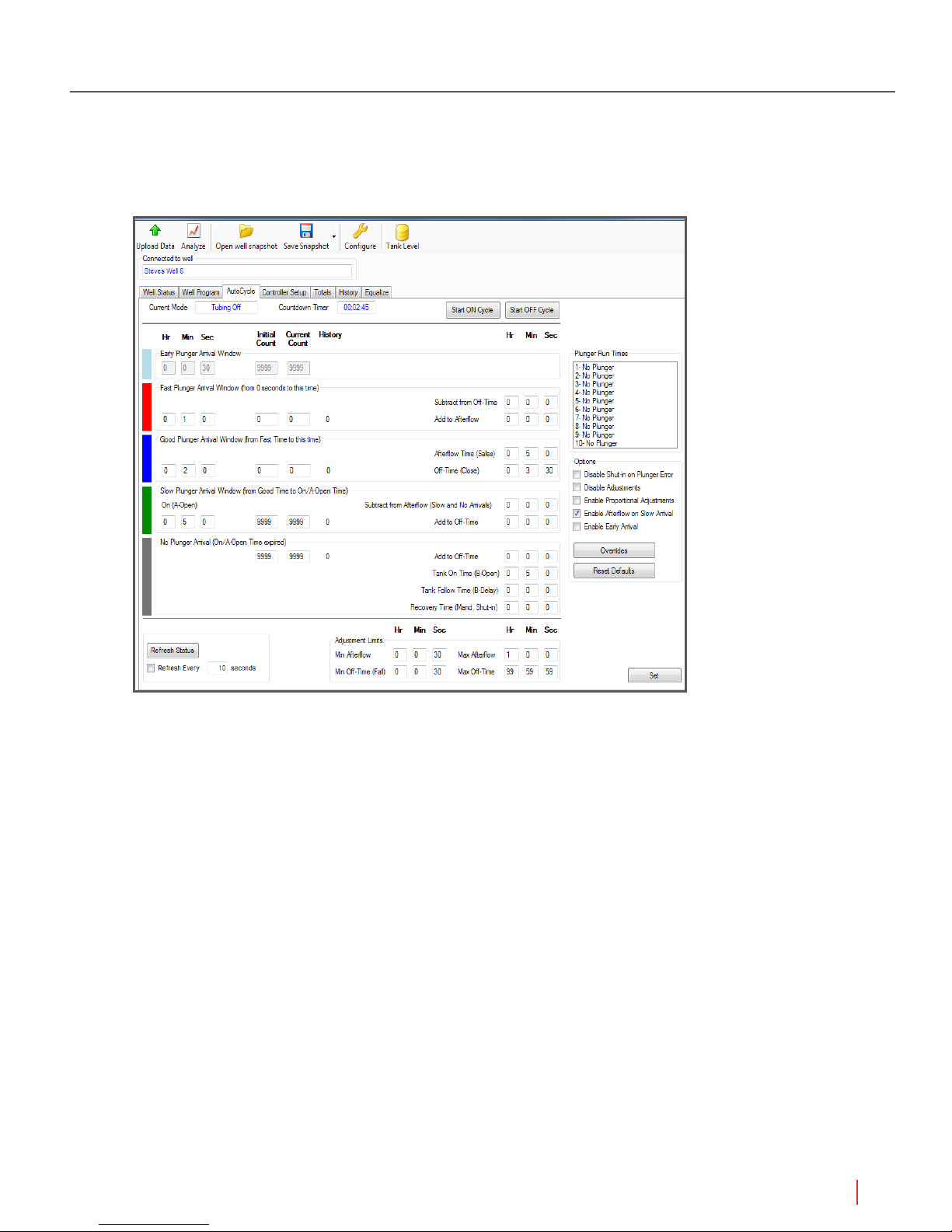
The gure below shows the AutoCycle tab. The user can accept default values that are based on
a depth of 8000 feet. The program can meet any level of control the user might want to apply. The
user can supply an initial set of times specic to the well and allow the AutoCycle program to adjust
automatically. Or the user can enter adjustments.
Figure 1.4 The AutoCycle Tab
To tailor the program to the well, the program has counters the user can change to match the
characteristics of the well. The following section describes the counters and the section after that
describes the adjustments.
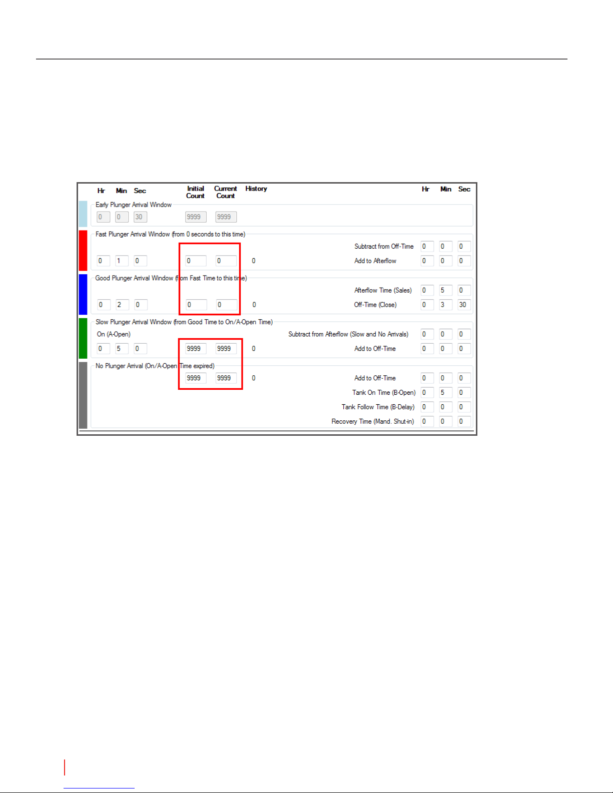
1.6.3 Plunger Arrival Counts
The user can adjust the AutoCycle program by providing arrival counts that are associated with
each window. Each window has an initial and a current counter.
• The Initial species the number of arrivals to match before the program responds. This count
remains at the default value until the user changes it. The program does not adjust this number.
• The Current counter displays the number of remaining arrivals required to trigger a mode
change. This counter reduces the value by one for each arrival in the window. When this
counter equals zero (0), the program changes to the mode appropriate for the type of arrival.
The counts that close the well require the arrivals to be consecutive such as Early, Slow, or
No Plunger. Requiring consecutive arrivals keeps the well open despite occasional plunger
errors but triggers a shut-in for a pattern of errors. The counts that move the well program
from A OPEN to SALES (AFTERFLOW) are nonconsecutive such as Fast and Good. The
nonconsecutive counts allow the well to produce for Fast or Good arrivals without interruption.
Understanding Plunger Lift Operations
17
Single Well Plunger Lift Controller Manual
The counters for Slow and No Plunger reset to the initial value immediately upon a Fast or
Good arrival. The Early counter resets upon a Slow or No Plunger arrival. The counters for Fast
and Good arrivals reset upon a Slow or No Plunger arrival.
The user needs to know the characteristics and pressures of the well to set the counts
appropriately. No single set of values works for all scenarios. The default values are a basic set
to begin operations.
Figure 1.5 The Default Values for Counts
Notice that the counts for the Fast Window are both zero (0). With these values, a Slow or No
Plunger resets the Current to the Initial. Zero (0) triggers the SALES (AFTERFLOW) mode with the
time adjustments for the Fast window. Therefore, a Fast Plunger always moves the program into
SALES (AFTERFLOW) mode.
18
Understanding Plunger Lift Operations

Single Well Plunger Lift Controller Manual
The same is true for the Good window default values. Notice that good arrivals have associated set
points and not adjustments.
• Current Afterow (Sales Time)
• Current Off-Time (Close Time)
• Min Off-Time (Fall Time)
• Max and Min limits on Afterow
Notice that the counts for the Slow window are equal at ve (5). After ve (5) consecutive Slow
arrivals, the Current count is zero (0) and the program enters CLOSE mode. The program applies
the time adjustments to inuence the next cycle toward a Good arrival.
As long as the arrivals are in the Slow window, the program adds to the Off-Time (Close Time) and
deducts from the Afterow time (Sales Time) of the next cycle. The program continues to adjust the
times until the plunger arrives in either a Good or Fast window. This change resets the Slow Count
from zero (0) to the Initial count of ve (5). The program continues to evaluate the arrivals and apply
adjustments based on the arrival type and the counts.
The following table summarizes the description of the counts:
For the
window…
Early Consecutive Any other arrival type CLOSE
Fast Nonconsecutive Any Slow or No arrival SALES
Good Nonconsecutive Any Slow or No arrival SALES
Slow Consecutive Nonconsecutive and Fast or Good
No Plunger Consecutive Any Fast or Good arrival CLOSE
* Unless the Enable Afterflow on Slow is selected on the AutoCycle tab
Table 1.3 Plunger Counts and Arrival Windows
Current shows # that
are… Current Resets to Initial on…
Mode triggered
when Current = 0
CLOSE*
arrival
Understanding Plunger Lift Operations
19
Single Well Plunger Lift Controller Manual
The following section describes the adjustments for the arrival windows and the set points of the
Good Window.
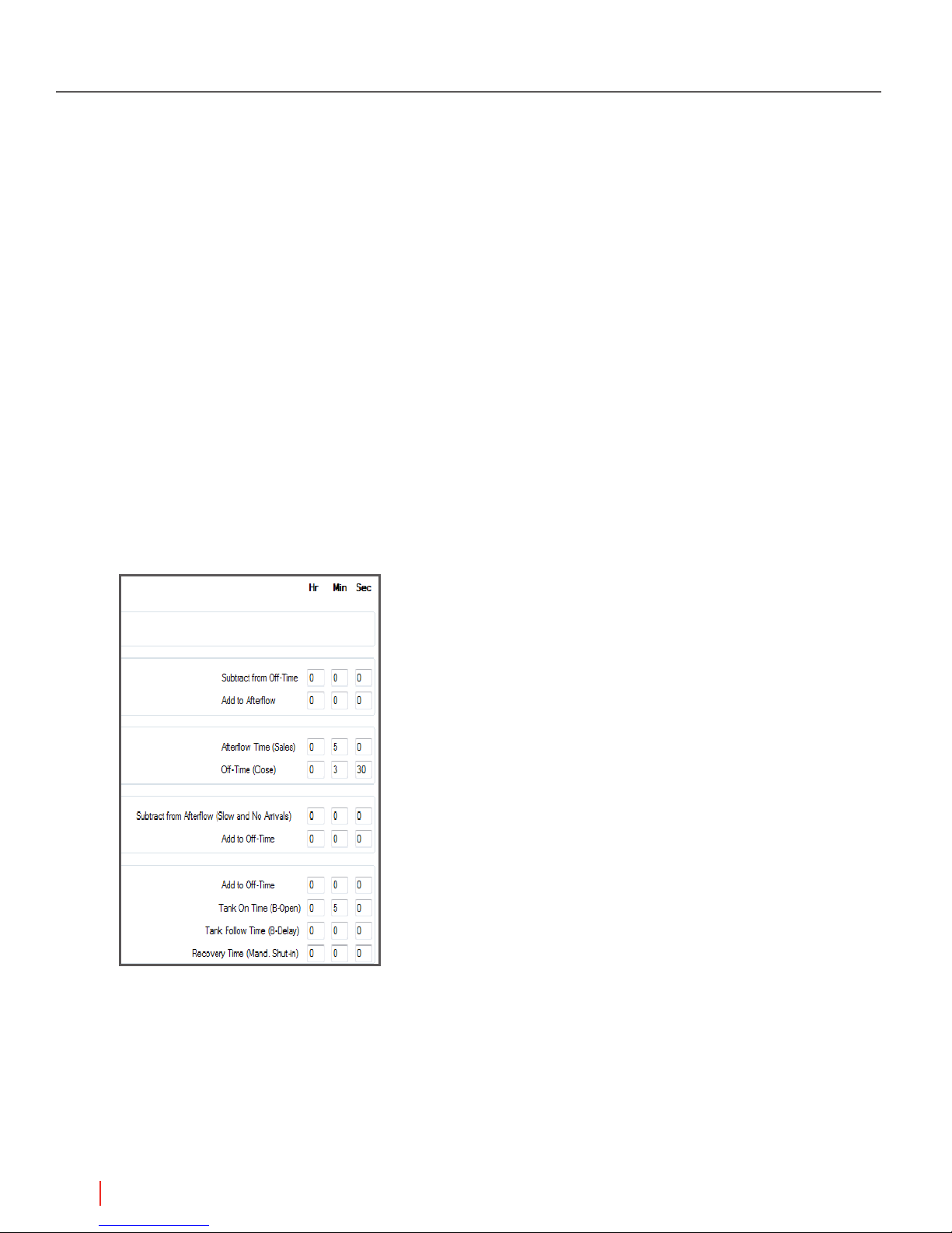
1.6.4 Automatic Time Adjustments
The AutoCycle program compares the actual time of arrival with the values of the window set
points. This comparison identies the speed of the plunger and the category of arrival. The program
applies the adjustments to the Afterow (Sales) time or the Off-Time (Close) if the plunger arrival
is outside the Good Arrival window and the count for the window is zero (0). The adjustments
can increase or decrease pressure to control the plunger speed. The Fast, Slow, and No Plunger
windows have adjustment set points the user can specify.
• Afterow (Sales) Afterow (Sales) relieves pressure after the plunger arrives. Shorter
Afterow (Sales) relieves less pressure for the next Tubing On (Open) mode while longer
Afterow cycles relieve more pressure. Less pressure slows speed and increases time it takes
for the plunger to arrive.
• Current Off-Time Adjustments Tubing Off cycles allow pressure to build in order to lift the
plunger and liquids to the surface. Longer Tubing Off (Close) modes result in more pressure
buildup: shorter Tubing Off (Close) modes result in less pressure buildup. More pressure
increase speed of the plunger and decreases the time it takes for the plunger to arrive.
Figure 1.6 Section of the AutoCycle tab for reading or specifying adjustments
Smaller Time Adjustments
The user can set the AutoCycle program to make proportional adjustments. Proportional
adjustments are partial adjustments based on how far the plunger arrival is from the Good Arrival
time.
20
Understanding Plunger Lift Operations

NOTE Best Practice If the arrival time is very close to the Good Arrival
window use the option for proportional adjustment.
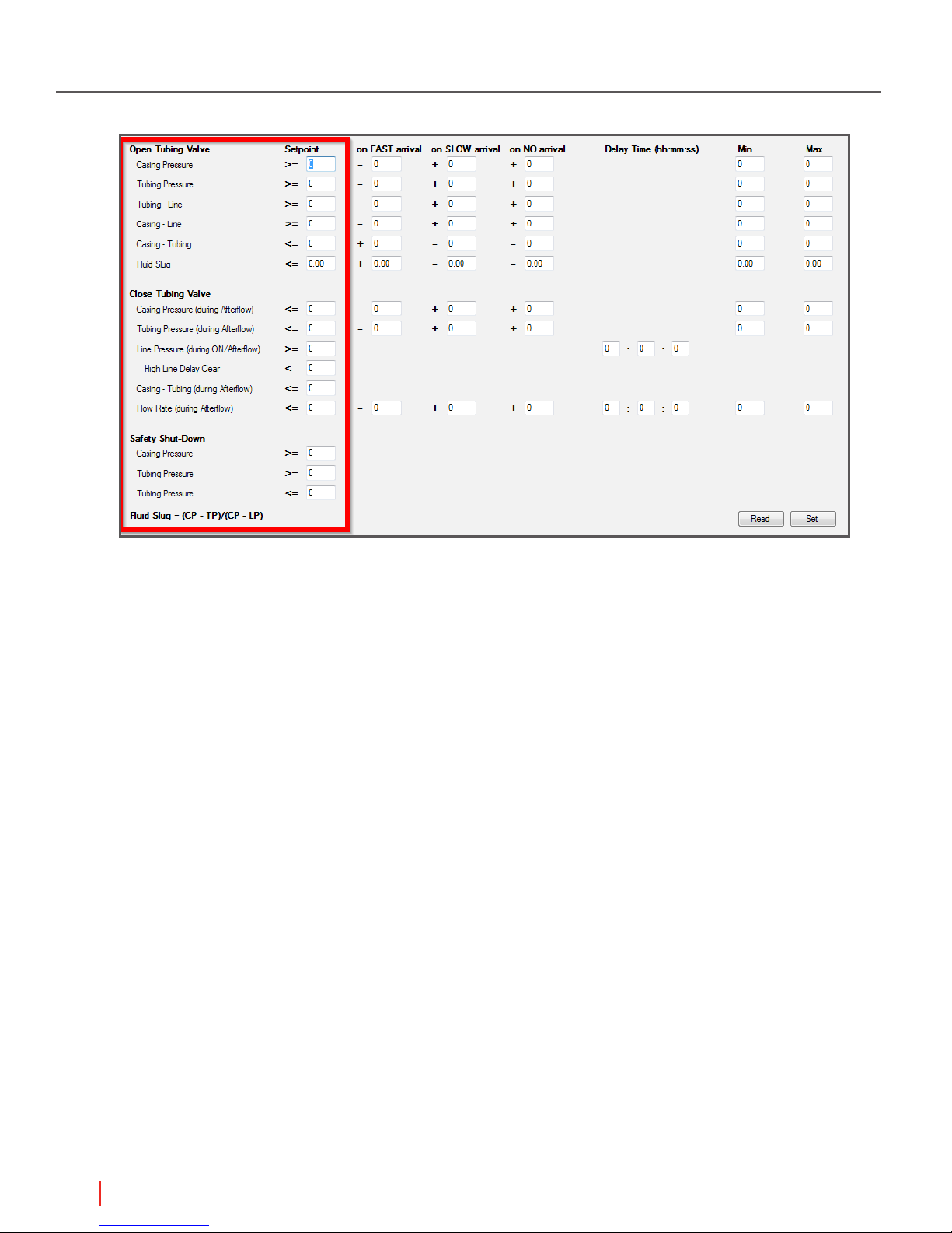
1.6.5 AutoCycle Pressure Set Points
The user can set the program to respond to pressure readings by using the Pressure Overrides
feature. The user can specify pressure set points or differentials that move the program from A
OPEN mode to AFTERFLOW (SALES) mode or to CLOSE mode.
The adjustments for the Casing Pressure, Tubing Pressure, and Differential Pressure Overrides on
Fast, Slow, and No Arrivals are available.
The user can specify pressure set points that change the mode of the AutoCycle program under
certain conditions. The following lists summarize the pressure conditions that trigger the production
value (Tubing Valve) to open or close.
Open Production Valve (Tubing Valve) Overrides
• If Casing pressure is greater than or equal to the set point
– Casing Pressure >=
Single Well Plunger Lift Controller Manual
• If Tubing pressure is greater than or equal to the set point
– Tubing Pressure >=
– If the differential of Tubing pressure and Line pressure is greater than or equal to the set point
– Tubing Pressure – Line Pressure >=
– Casing Pressure – Line Pressure >=
– Casing Pressure – Tubing Pressure <=
– Fluid Slug <= Casing Pressure – Tubing Pressure / Casing Pressure – Line Pressure
Close Production Valve (Tubing Valve) Overrides
• If Casing pressure is less than or equal to the set point
– Casing Pressure <=
• If Tubing pressure is less than or equal to the set point
– Tubing Pressure <=
• If Line pressure is greater than or equal to the set point
– Line Pressure >=
– A delay time is optional
– Shuts in the well until the condition is no longer met
– High Line Delay Clear <Casing - Tubing <= (during afterflow)
– Flow Rate <= (during afterflow)
Safety Shut-Down
– Casing Pressure >=
– Tubing Pressure >=
– Tubing Pressure >=
Understanding Plunger Lift Operations
21
Single Well Plunger Lift Controller Manual
The gure below shows the AutoCycle Pressure Overrides dialog box.
Figure 1.7 The dialog box for pressure set points
By using the pressure overrides, the user sets the program to respond to the current pressure
readings in addition to the passing of time.
22
Understanding Plunger Lift Operations
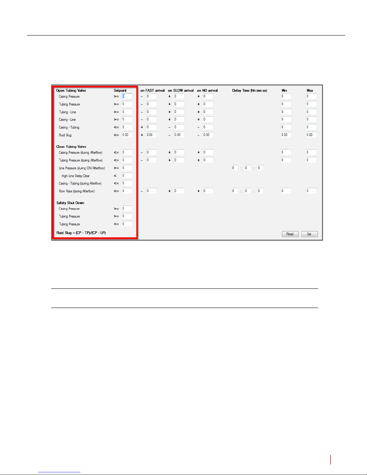
1.6.6 Automatic Adjustment of Pressure Set Points
The user can set the program to adjust the pressure set points for the next cycle based on the
plunger arrival.
Single Well Plunger Lift Controller Manual
Figure 1.8 Adjustments to Pressures for the Arrival Windows
After the user has enabled the program, the user can analyze the results of the optimization
program.
NOTE For more information, see “Well Program Set Points for AutoCycle” in the
Reference section of the Help Documents.
Understanding Plunger Lift Operations
23

Single Well Plunger Lift Controller Manual
2 Set Points for Plunger Lift
Operations
The user can analyze the well’s performance over time and ne-tune the production method based
on trending data. A user examines a current analysis of a well’s performance to set and adjust the
frequency of the plunger cycles based on conditions of the well. The rate of liquid accumulation is
unique to each well. Changes to the production valve state control the plunger cycle. An electronic
controller at the surface automates the state of the production valve.
NOTE For more information about plunger cycles, see “Understanding Plunger
Lift Operations” in this manual.
NOTE For information about specifying a Well Program, see “Configuring Single
Well Production” in the Guides section of the Help Documents.
This document organizes the set points into control and adjustment categories:
Control Production Modes
Adjustments to Open Pressure Values
Adjustments for Plunger Misses
Control Exit of SALES Mode
Control Shut-in
Control Alarms
The user can specify the following set points to adjust when and how the controller directs the Well
Program to respond to well conditions.
2.1 Control Production Modes
The user chooses the set points depending on the well conditions and the production method.
For the Time method, if Well Program’s value for sales time is 00:00:00, the controller closes
the production valve when the plunger arrives. For a pressure method, the controller opens the
production valve in response to wellhead pressures. On the Well Program tab, the WellVision
application offers only the set points appropriate for the method. The other set points are visible
but gray.
24
Set Points for Plunger Lift Operations
Single Well Plunger Lift Controller Manual
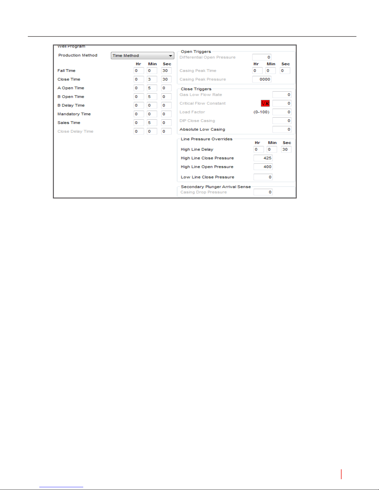
Figure 2.1 Program Values area shows the set points available based on the production method
2.1.1 Fall Time (All Production Methods)
Format: HH:MM:SS
Typical Value: 1:00:00
Disable Value: 00:00:00
Specify a minimum shut-in time to allow the plunger to fall to the bottom of the well. During Fall
Time, the user must use the Go to A open mode on the Status tab of the well or use the ON button
on the Walk Up Display to open the well. The controller does not use other set points to direct the
well to open during this time.
2.1.2 Close Time (All Production Methods)
Format: HH:MM:SS
Typical Value: Time method: 2:00:00: Pressure methods: 00:00:00
Legacy Label: TUBING OFF
Specify a shut-in time that ensures pressure build up in the well to surface the plunger with a liquid
load before the controller opens the production valve for the next production cycle.
Usage: For pressure methods, this set point is typically set to 00:00:00 because the controller
opens the production valve in response to changes in pressure. If the user wants the production
valve to open after time regardless of pressure changes, the user can set the Close Time. If a Close
Time is set, the value must be greater or equal (>=) the Fall Time.
Set Points for Plunger Lift Operations
25

Single Well Plunger Lift Controller Manual
2.1.3 A Open Time (All Production Methods)
Format: HH:MM:SS
Typical Value: Time method: 1:00:00
Legacy Label: Open Time, TUBING ON for the Sales valve
Specify the time that the well is open and gas is owing through the production valve. During Open
Time, the plunger starts to surface and the well produces its initial head gas. Allow enough timing
for the plunger to surface with the liquid load. A zero time setting (00:00:00) leaves the well open
indenitely or until a plunger arrival triggers Sales Mode.
2.1.4 Sales Time (All Production Methods)
Format: HH:MM:SS
Disable Value: 00:00:00 to close the A Valve on plunger arrival
Legacy Label: DELAY TIME, Afterow Time
Specify additional time the controller allows gas ow after the plunger arrival. The countdown starts
after the plunger sensor detects the plunger at the wellhead surface.
Usage: Typically, the user sets this value as a backup to close the well if the well conditions do not
meet other set points within an appropriate time.
For example, the well’s production might be highest when based on meeting a certain pressure,
rate, or other value. Typical set points might be one of the following:
• D.I.P Close Pressure
• Low Gas Flow Rate
• Critical Flow K Factor
NOTE Set the Sales Time higher than the normal time the well is able to sell gas.
2.1.5 Delay Close Time (Pressure methods)
Format: HH:MM:SS
Disable Value: Use 00:00:00
Specify the time to wait and evaluate whether an increase in the casing pressure is a brief spike or
an actual, sustained increase. This set point is evaluated and effective during SALES MODE only.
The user can set this to work with Low Gas Flow Rate also.
NOTE For more information about this set point and the modes, see “Pressure
Set Points and the Time Method” in the “Understanding Plunger Lift
Operations” document of the Concepts section.
26
Set Points for Plunger Lift Operations
 Loading...