

Page 1

PCS Electronics
www.pcs-electronics.com
info@pcs-electronics.com
RDS MAX V1.0
RDS MAX v1.0 is a high quality and cost effective way to add RDS capability to your transmitter. It has been designed especially to
complement the PCI MAX and other FM transmitters from PCS Electronics. Our main guideline was to have an option of transmitting
MP3 IDtag with the radio text. This unit will allow for dynamic PS, TA, AF, RT, DI, PTY, TP, PI and possibly CT (still evaluated).
Simple assembling procedure, high quality components and printed circuit board assure 24/7 operation for years.
Features:
MPX input: 6K
MPX output: 75 ohms
Supply voltage: 12V-16V/100mA DC
Input connector: RCA
Output connector: RCA
Output level:
RDS pilot: 57KHz, PLL locked to stereo pilot
RDS groups supported: 0A, 2A
Functions: PS, AF, RT, TA, DI, PTY, TP, PI
Galvanic separation with the PC, eliminates ground loops (brum)
PC data connection: RS232
Automatic switch from internal pilot to stereo synchronized pilot
THANK YOU FOR PURCHASING RDS MAX V1.0!
We hope you will enjoy it as much as we do and remember to tell your friends about it. If you discovered a bug and perhaps even found a
solution or have an idea for improvement of this product, please don’t hesitate to contact us.
Please feel free to send us your comments to feedback@pcs-electronics.com. For tech support please send email to support@pcs-
electronics.com
From all of us we wish you happy broadcasting!
PCS Electronics
www.pcs-electronics.com
Now go get that soldering iron :-)
BEFORE YOU START
Here is what you need to use RDS MAX V1.0
-Soldering iron; 25-35 watt soldering iron. Weller and ERSA make excellent soldering tools. Radio Shack stuff is horrible, but will do if
that’s your only option. This may not be needed with some configurations (enclosed).
-FM exciter (a transmitter); You will need a transmitter that will transmit the RDS signal. It has been designed specifically for the MAX
family of transmitters, but can be used with any FM exciter.
Finally, if you know nothing or little about electronics, I selected a few books that I find extremely useful and often read. The links to them
are on our homepage. I suggest you start with ARRL HANDBOOK, the holy bible of amateur radio and electronics in general. It is an
extremely valuable resource for every broadcaster.
USING THE RDS MAX v1.0
Step 1: Unwrapping the package
Clean-up that desk and carefully unwrap the package. Depending on the configuration of the purchased RDS encoder you will either find just
the PCB with the CD or the encoder mounted into an enclosure with encoder and cable. Sometimes we don’t send the CD since some
countries have strict regulations pertaining to import of CDs (Mexico is a good example of this). If this is the case, you are advised to
download your driver from our website.
Quickly check the PCB for any defects inflicted by the shipping. If all checks out fine, proceed to the next step.
Step 2: Connecting to the transmitter, PC and stereo encoder
This is the most difficult part of the job. Still, with little patience, good instructions and steady hand it should be a breeze with most users. If
you’re stuck at some point, don’t hesitate to contact us with your questions. Note that we have a Forum on our website; you can post your
questions there also. Let’s look at the typical scenarios with RDS MAX v1.0.
Fig. 1; RDS MAX v1.0 without the enclosure
Page 2

SCENARIO 1: MAX PRO I, SE3 and RDS MAX v1.0 (simple)
The advantage of this setup is its obvious
simplicity. You don’t even have to solder; the only
exception is the positive supply voltage of 12V,
which is really simple. If you are doing this with
the enclosed version of RDS MAX, you don’t even
have to solder anything since there is a connector
for the power supply.
While this setup generally works very well it does
have one small disadvantage. Depending on the
audio content there could be a bit of jitter on the
RDS data carrier.
We’d like to point out here that you should keep
the wires short and mount this setup in enclosure or
separate enclosures.
Install a jumper on J5, place it to the right away
from the edge of the PCB.
Advantages:
-Simple
-Pilot is extracted automatically
-No alignment necessary (when used with PCS
transmitters)
Disadvantages:
-Audio can cause a bit of RDS pilot jitter
SCENARIO 2: MAX PRO I, SE3 and RDS MAX v1.0 (advanced)
If you know how to install an extra cable for the pilot, this is definitely worth doing. The above connections from scenario 1 stay in place
with scenario 2. The only difference is in a way in which we extract stereo pilot and send it over to the RDS encoder. This is now done via a
dedicated cable. The reason for this is the above mentioned jitter on the pilot. Here’s what you have to do to set this up:
-Connect all cables as shown above
-Connect a short coaxial audio cable from C23 on SE3 (stereo encoder pilot) to the J4 on RDS MAX V1.0.
-Install a jumper on J5, place it to the left towards the edge of the PCB
Advantages:
-No alignment necessary (when used with PCS transmitters)
-Better signal quality
Disadvantages:
-A bit more complex
2
Page 3

SCENARIO 3: PCI MAX ULTRA and RDS MAX v1.0
For all those who have been wondering; yes, it can be done! There are two things we need to do here.
First, get the stereo pilot to the RDS MAX board so it can phase lock its RDS data pilot and
second, get the RDS data signal back to the PCI MAX board. The picture on the left
illustrates this really well. This is how we pick up pilot from PCI MAX and send it over to
the RDS encoder. Remember, this must be done with a shielded coaxial audio cable
(microphone cable) and this cable should be kept short. The other end goes to jumper J4 on
the RDS MAX board. Install a jumper on J5, place it to the left towards the edge of the PCB.
Next, we must inject RDS data into the PCI MAX card. We will need another shielded
coaxial cable to do that. This cable will go from MPX out RCA jack on the RDS MAX board
to the point on the PCI MAX ULTRA board. Also replace the 75 ohms resistor close to the
MPX OUT connector with a 10K resistor. You can also place this resistor between the output
(MPX OUT) and the coaxial cable (inline). The next picture below shows where the RDS
signal from the RDS MAX 1.0 goes on the PCI MAX ULTRA board.
Step 3: Software
Install the RDS MAX program from the provided CD or download the latest version from our website. Set the used COM port in the Setup
dialog. Please send us any bug reports or suggestions for improvement. We will take your comments into consideration.
Step 4: Power up and use
If you’re running stereo signal and D2 isn’t lit, adjust P1 until it is. That’s pretty much all there is to it. If you’re using another FM
transmitter and stereo encoder, you may need to increase/decrease the level of RDS data signal. This can be done with changing the 15K
resistor (R7) on the RDS MAX board.
Troubleshooting
We hope you’ll never get to this step. We all know bad things happen. But do not despair! If you have problems that you cannot solve
yourself, please contact us directly support@www.pcs-electronics.com. Feel free to post questions to our forum and discuss matters with
other users.
2
Page 4
Newsletter
You may want to sign up for out newsletter so you can receive the latest news and special deals. Also check our forum and discuss tips and
tricks with other users, you never know you just may learn something. You can sign up at www.pcs-electronics.com
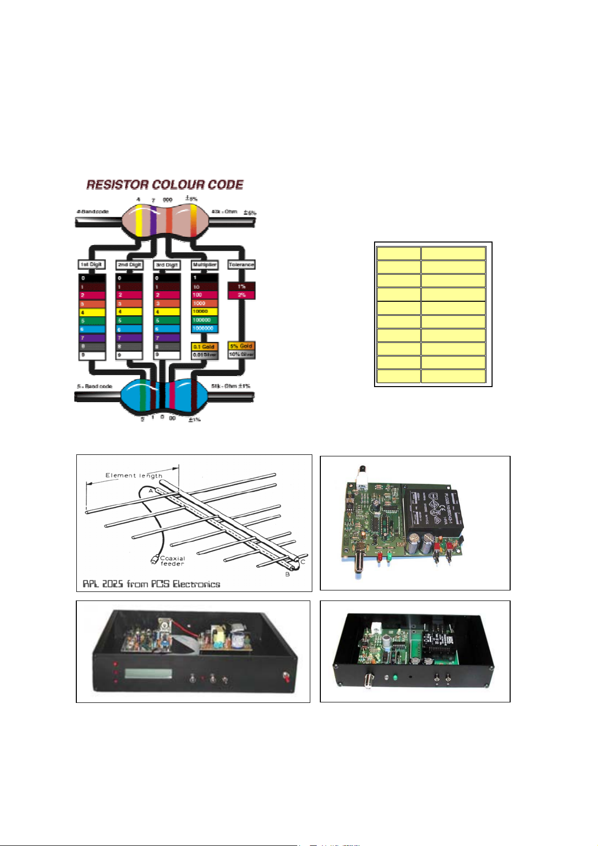
Appendix A: The resistor color codes
The easiest method is to get radio Shack part number 271-1210 for $1.19; it is a pocket sized card with spin dials. Just spin the dials to show
the correct colored bands and read the resistance off the card. Sort of a resistor slide rule. And as you’ve probably guessed, it’s also on our
site.
0 Black
1 Brown
2 Red
3 Orange
4 Yellow
5 Green
6 Blue
7 Violet
8 Grey
9 White
Also available from PCS Electronics
Directional antennas, 5W boosters, stand-alone FM transmitters and much much more…
Check www.pcs-electronics.com!
2
Page 5
Bill of Materials RDS MAX V1.0
Qty Value Reference
1 NE5532P IC1
1 MC1310P IC2
1 4017 IC3
1 4046 IC4
1 TDA7330D IC5
1 4066 IC6
1 4030 SMD IC7
1 4013 SMD IC8
1 90S2313 - 10 IC9
1 24C64 (24C32) ATMEL IC10
1 78L05 IC11
1 78L09 or 78L10 IC12
1 CNY17 IC13
2 RCA connector for PCB J1, J2
1 DB9F connector, PCB, 90 degrees J3
1 Pilot input, optional J4
1 Auto/manual pilot input selection, optional J5
1 4.332 MHz Q1
1 9.8304 MHz Q2
1 LED Green (+681 resistor under the pcb) D1
1 LED RED – Pilot lock to stereo encoder D2
1 Wire bridge D3
1 75 Metal R1
4 6K8 Metal R2, R3, R6, R9
6 10K R4, R5, R13, R16, R19, R20
1 15K Metal R7
2 33 R8, R12
5 1K R10, R11, R15, R22, R23
2 1K SMD under the 24C64
1 330K R14
1 330 R17
1 2M2 R18
1 1K, special placement R21
1 10K trimmer P1
1 15pF C1
6 68-150nF C2, C4, C5, C9, C11, C15
4 10uF C3, C6, C7, C20
2 680pF C12, C32
1 1nF C19
1 1uF (yellow) C16
9 47-100nF C8, C13, C14, C17, C18, C21,
4 22pF C23, C24, C28, C29
2 10nF C10, C25
1 DIL 20 socket for IC9
1 DIL8 socket for IC10
1 PCB
Checklist (√)
C22, C26, C31
Limitation of liability
To the maximum extent permitted by applicable law, in no event shall PCS Electronics or its suppliers be liable for any special, incidental,
indirect, or consequential damages whatsoever (including, without limitation, damages for loss of business profits, business interruption, loss of
business information, or any other pecuniary loss) arising out of the use of or inability to use the PRODUCT, even if PCS Electronics has been
advised of the possibility of such damages. In any case, PCS Electronics’ entire liability under any provision of this agreement shall be limited to
the greater of the amount actually paid by you for the PRODUCT or U.S. $5.00; because some states and jurisdictions do not allow the exclusion
or limitation of liability, the above limitation may not apply to you.
LEGAL INFO
It may be illegal to operate this device in your county. Please consult local authorities before using RDS MAX V1.0!
WARNING
Please note that there is high voltage present inside the RDS encoder (the version in enclosure with mains power supply). Do not touch
any of the exposed circuits or parts once the unit has been connected to the mains voltage. Failure to follow this might result in serious
injury or even death. Always unplug the mains cable before opening this unit and tampering inside the unit!
2
 Loading...