

Page 1
Brought to you by PCS Electronics, www.pcs-electronics.com
1
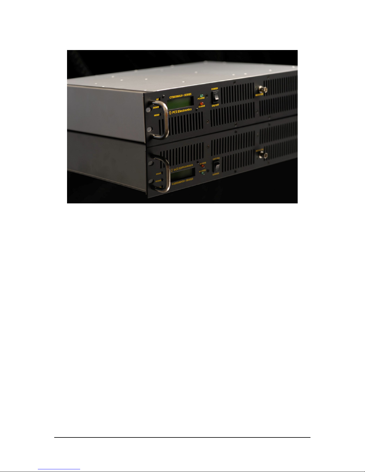
CyberMaxFM+ DSP/RDS
High performance FM radio broadcasting exciter
Covers 150W, 300W, 500W and 750W models, silver and black front
panel
Manual
Page 2

Brought to you by PCS Electronics, www.pcs-electronics.com
2
I M P O R T A N T N O T E
- Upon receiving your order inspect the packaging material and unit for apparent damage.
Any damage should be reported immediately so we can make a claim with the shipping
company. Take photos, if you can, they can be used as a proof.
- Mains cable is typically not included with our mains power supplies and units. Since these
cables vary from country to country and we had trouble finding the exact type we decided
against including them, especially since finding them is so easy and cheap locally. They can be
obtained in any radio/computer/hardware shop at the cost of about 1 US$. It is the type used in
your PC for mains power.
- Study local regulations and ensure you are always operating in compliance.
- Do not open the unit or attempt service yourself. Deadly mains voltage is present inside. There
are also high RF voltage points that can cause burns and discomfort if touched.
- If you are using ¾ Exterminator antenna make sure you first extend all the telescopic tubes all
the way to black marker ring. This ring has been drawn during the tune-up procedure. Also verify
SWR with SWR meter as transport or installation can affect resonant frequency slightly.
- Finally, never ever operate any transmitter or amplifier without a properly tuned antenna!
Page 3

Brought to you by PCS Electronics, www.pcs-electronics.com
3
TABLE OF CONTENTS
INTRODUCING CYBERMAXFM+ SERIES OF TRANSMITTERS................................ .......................... 5
WHAT MAKES THIS FM TRANSMITTER SERIES SO GREAT?................................................................................. 5
GENERAL FEATURES ....................................................................................................................................... 5
TECHNICAL SPECIFICATIONS ........................................................................................................................... 6
THANK YOU FOR PURCHASING CYBERMAXFM+ TRANSMITTER........................................................................ 6
FRONT AND BACK PANEL LAYOUT ................................................................ ....................................... 7
WHAT’S INSIDE THE BOX? ................................................................ ....................................................... 9
FM EXCITER BOARD..................................................................................................................................... 10
STEREO ENCODER BOARD.............................................................................................................................. 12
RDS ENCODER BOARD .................................................................................................................................. 13
WHERE CAN I FIND MORE INFO? .................................................................................................................... 13
BEFORE YOU START ................................................................................................................................ 14
ANTENNA..................................................................................................................................................... 14
SO WHAT IS THIS SWR (VSWR) EVERYONE TALKS ABOUT?........................................................................... 15
COAXIAL CABLE ........................................................................................................................................... 15
MAINS POWER SUPPLY AND MAINS POWER CABLE .......................................................................................... 15
AUDIO SOURCE WITH MI XER, MICROPHONE ETC ............................................................................................. 15
WIRING EVERYTHING TOGETHER ...................................................................................................... 16
WIRING THINGS UP AND FIRST POWER-UP....................................................................................................... 16
USING THE CYBERMAXFM+ SERIES TRANSMITTER....................................................................... 17
LCD CONTROL MODULE MENU SYSTEM: POWER AND DSP FUNCTIONS ............................................................ 17
CHANGING FREQUENCY ................................................................................................................................ 17
<RF POWER>............................................................................................................................................. 17
<STEREO MODE>..................................................................................................................................... 17
<VIEW SELECT>....................................................................................................................................... 18
<TREBLE> AND <BASS> (ONLY WITH DSP STEREO ENCODERS).................................................................. 18
COMPRESSOR SETTINGS (ONLY WITH DSP STEREO ENCODERS)....................................................................... 18
<LCD CONTRAST>................................................................................................................................... 19
LEFT AND RIGHT CHANNEL VOLUME (ONLY WITH DSP STEREO ENCODERS)..................................................... 19
<PLL STEP>............................................................................................................................................... 20
<FIRMWARE VER> .................................................................................................................................. 20
<CURRENT ALARM> ............................................................................................................................... 20
<TEMP ALARM>....................................................................................................................................... 20
<SWR ALARM>......................................................................................................................................... 20
<U AMP ALARM>..................................................................................................................................... 20
<BAND SELECT>...................................................................................................................................... 20
<RF AMP CONTROL>............................................................................................................................... 20
<RF POWER ALC> .................................................................................................................................... 21
DESCRIPTION OF WINDOWS CONTROL PROGRAM................................ ......................................... 22
SETUP .......................................................................................................................................................... 22
FM TX MAIN ............................................................................................................................................... 23
FM TX ALARMS........................................................................................................................................... 25
PI, PTY... .................................................................................................................................................... 26
PS0.............................................................................................................................................................. 27
PS1.............................................................................................................................................................. 28
PS2.............................................................................................................................................................. 28
TIME, MSG................................................................................................................................................. 29
AUTO PS, RT... .......................................................................................................................................... 30
ABOUT......................................................................................................................................................... 31
Page 4

Brought to you by PCS Electronics, www.pcs-electronics.com
4
COMMON CONTROLS..................................................................................................................................... 32
SCHEDULER.................................................................................................................................................. 33
TROUBLESHOOTING ................................................................ ............................................................... 35
APPENDIX A: DIY ANTENNA AND IMPROVEMENT TIPS ................................................................ . 37
SIMPLE GP ANTENNA DESIGN........................................................................................................................ 37
SOME MORE IMPROVEMENT TIPS.................................................................................................................... 37
APPENDIX B: GENERAL TIPS FOR SETTING UP TRANSMITTERS ................................................. 38
TYPICAL FM TRANSMITTER SET UPS .............................................................................................................. 38
TYPICAL FM BROADCASTING ANTENNA SETUPS............................................................................................. 39
WIRING ANTENNAS IN MULTI-BAY CONFIGURATIONS ..................................................................................... 40
APPENDIX C – ATTACHING EXTERNAL STEREO PROCESSOR...................................................... 41
APPENDIX D – PC REMOTE CONTROL VIA USB AND RS232............................................................ 42
SOFTWARE INSTALLATION ............................................................................................................................ 42
CONFIGURING COMMUNICATIONS PORT ......................................................................................................... 43
INSTALLING USB DRIVER (ONLY FOR USB IO BOARD) .................................................................................. 43
CONFIGURING USB DRIVER .......................................................................................................................... 43
APPENDIX E – SETTING UP REMOTE CONTROL VIA ETHERNET ................................................. 45
SOFTWARE INSTALLATION ............................................................................................................................ 45
APPENDIX F: WHAT IS RDS?................................................................ ................................................... 48
APPENDIX G – WARRANTY AND LEGAL INFO................................................................................... 58
IMPORTANT NOTICE!..................................................................................................................................... 58
WARRANTY AND SERVICING! ........................................................................................................................ 58
LEGAL INFO.................................................................................................................................................. 58
LIMITATION OF LIABILITY ............................................................................................................................. 58
ALSO AVAILABLE FROM WWW.PCS-ELECTRONICS.COM............................................................. 59
REVISIONS AND ERRATA................................ ........................................................................................ 60
INDEX................................ ........................................................................................................................... 60
Page 5

Brought to you by PCS Electronics, www.pcs-electronics.com
5
Introducing CYBERMAXFM+ series of transmitters
Our series of rack mounted stereo FM radio transmitters
with optional RDS and DSP processing
his manual covers our 150W/300W/500W and 750W CYBERMAXFM+ transmitters. Even though the design
of these units evolved radically over the years transmitters from this series remain one of our best selling items.
Today our customers still enjoy the incredible price/performance ratio and more reliability, power and features
than ever before. In this manual you’ll find all of this products little secrets.
Please note that while these transmitters are all based on the same technology some may have a different mains power
supply and different amplifier module, but they are internally almost identical.
What makes this FM transmitter series so great?
Besides offering all the standard basic features these units also display a number of useful parameters on the LCD display:
transmitted power, reflected power, exciter temperature, exciter voltage, frequency, audio modulation level, amplifier voltage,
and amplifier temperature. They are available in mono (MPX input) and stereo (with regular or DSP stereo encoder). RDS
(Radio Data System) option is also available. Of course this unit is completely no-tune and works from any mains voltage
(110-240V 50/60Hz) available worldwide.
Comfortably sized 2H 19" rack enclosure offers easy access to all internal components and assures good ventilation. A
number of protection circuits helps prevent disasters. Temperature and SWR are monitored by on-board computer and
alarm threshold can be set via LCD module. Hardware fold back SWR protection is also built-in as a backup. Unit is rugged
and made for 24/7/365 operation. In our opinion it gives the best quality/price ratio possible.
General features
- True wideband no-tune operation (no tuning required to make it work, just set the frequency and desired output power)
- Covering entire FM broadcasting band with clean signal and great sounding audio
- Built-in SWR and TEMP protection for peace of mind
- High power (150W/300W/500W/750W depending on the model)
- Digital output power adjustment (with up/down keys and LCD display)
- Both DSP and analog models have extremely sharp audio filters
- DSP model offers complete control over audio parameters via LCD menu system
- Optional high-performance RDS encoder with scrolling PS and many other features.
Chapter
1
T
Page 6

Brought to you by PCS Electronics, www.pcs-electronics.com
6
Technical specifications
RF section:
- Frequency range: 87.5-108MHz
- RF Output Power: 0 to full (digitally adjustable with UP/DOWN keys or remotely via PC)
- Output connector: N female (50-750W models)
- Output Impedance: 50 Ohms
- PLL steps: 5KHz (10/25/50/100/200KHz adjustable via LCD)
- Frequency stability: +/- 20Hz
- Spurious/Harmonic rejection: Harmonics: >50dB, Spurious: -90dB
- RF output ruggedness: SWR protection, TEMP protection, reduced power with LCD warning and RED LED
- Quartz locked PLL frequency control, ultra stable & clean output
- S/N ratio: >90 dB
- No expensive test equipment required to setup
Audio section:
- Audio performance: Less than 0.2% distortion, 20Hz-75KHz
- Pre-emphasis, 50uS, 75uS or none selectable
- Audio Input Level: 0 dB
- Stereo separation: > 50dB
- Audio low pass filter with 19KHz notch filter: Yes, all models
- Audio input impedance: 10Kohms balanced, 1Kohms unbalanced
- Limiter: Yes, all models
- Pre-emphasis: Yes, precision 50uS, 75uS or none for all models
- DSP: Yes, in DSP models
General:
- Mains power: 110-240V/50-60Hz, universal worldwide, IEC male at the back (cable typically not included)
- LCD display shows: Power, reflected power, frequency, temperature, supply voltage, modulation level and uptime counter
- Ambient temperature: -10C° to +40°C, air conditioning in transmitter room strongly advisable for long life
- External dimensions: 150W-300W ( W x D x H ) 19" x depth (315mm) x height 2HE (88mm), ~6Kg
- External dimensions: 500W-750W ( W x D x H ) 19" x depth (~370mm) x height 2HE (88mm), ~10Kg
Thank you for purchasing CyberMaxFM+ transmitter
We hope you will enjoy it as much as we do and if you do remember to tell your friends and colleagues about it. Please feel
free to leave your comments at our website or post your experience in our forum. And if you encounter a problem please let
us know so that we may improve our products, offer advice and suggestion. From all of us we wish you happy broadcasting!
Your PCS Electronics team
Page 7
Brought to you by PCS Electronics, www.pcs-electronics.com
7
Front and back panel layout
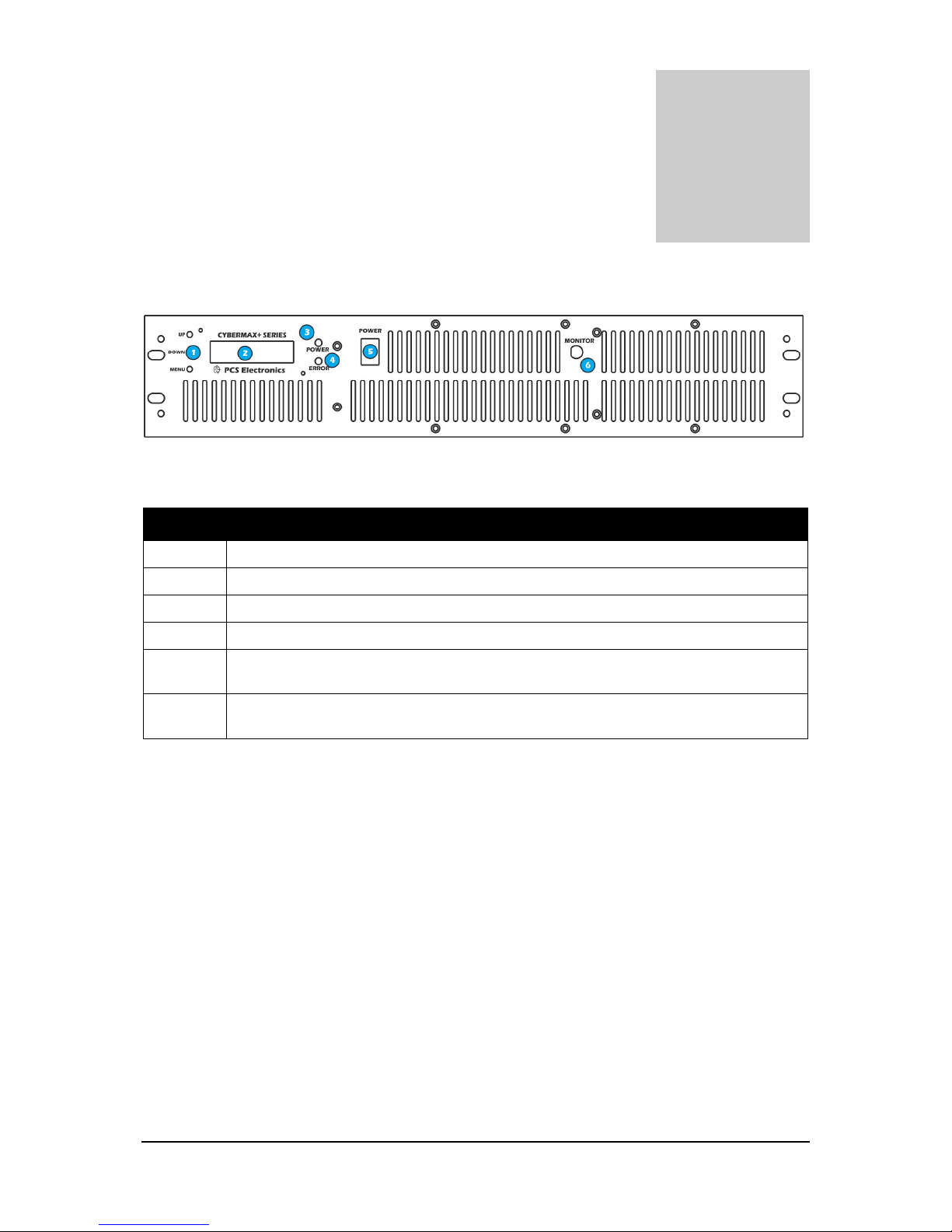
Fig. 1: Front panel
Reference Function
1 Three push buttons, the UP, DOWN and MENU keys.
2 LCD display that lets you control the unit and monitor various parameters.
3 The green led. Green signals power is ON.
4 Red error led. Turns on while VCO is tuning into selected frequency and in case of SWR or TEMP error.
5 Power switch in the middle of the panel is actually a standby switch. To really fully disconnect the unit
from mains power use the main switch at the back.
6 Monitor output at the front provides a small sample of the transmitter signal, this can be used to attach
frequency counter, modulation index monitor, spectrum analyzer or similar equipment.
Chapter
2
Page 8
Brought to you by PCS Electronics, www.pcs-electronics.com
8
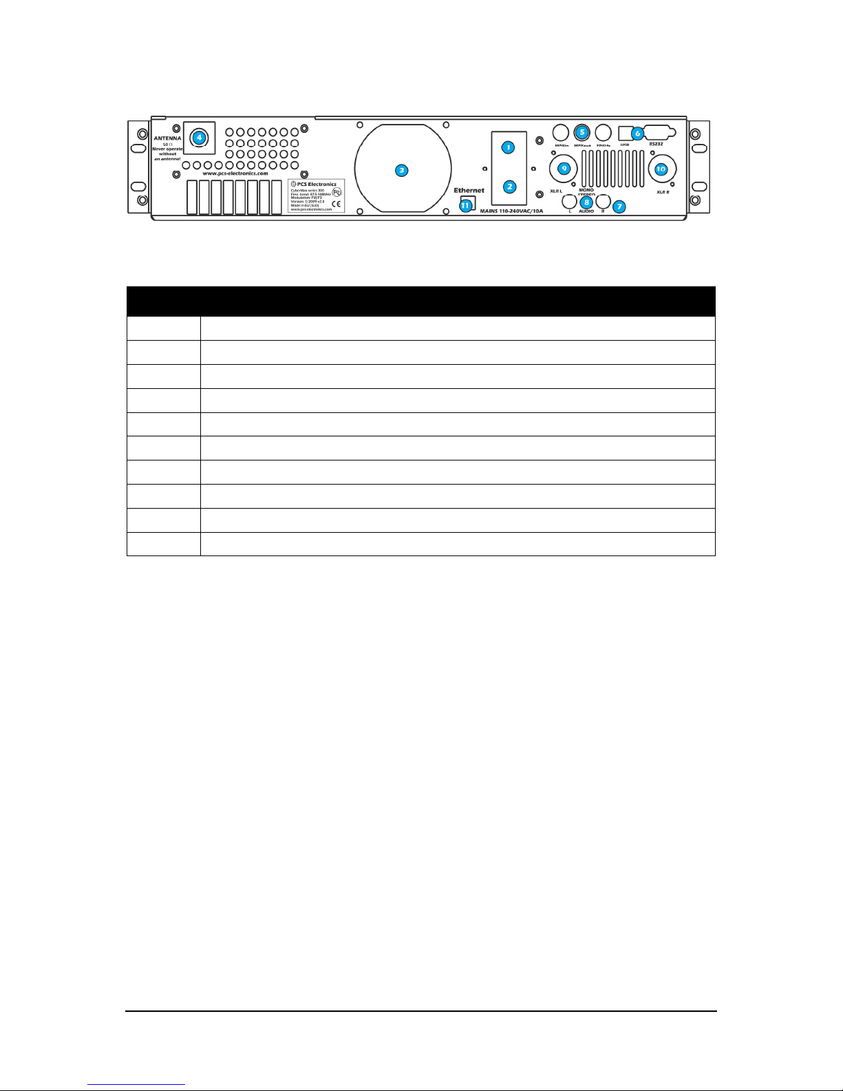
Fig. 2: Back panel
Reference Function
1 Mains power, universal input 110-240V, IEC jack (same as for PC)
2 Fuse and main mains switch (total off)
3 Ventilation aperture
4 Antenna connector, N female. Do not operate without antenna.
5 BNC connectors for MPXin, MPXout and 19KHz pilot.
6 RS232/USB for controlling your RDS encoder and FM transmitter.
7 Audio inputs, RCA jacks for left and right channel
8 STEREO mode indicator.
9, 10 Balanced audio inputs, left and right channel XLR (Canon)
11 Ethernet (optional) port for controlling/monitoring RDS and FM transmitter.
Page 9
Brought to you by PCS Electronics, www.pcs-electronics.com
9
What’s inside the box?
CyberMaxFM+ transmitters are available in several configurations. Exact internal configuration depends on the particular
model. Since we sometimes change configurations it is best to check our website for latest information. Below are the basic
building blocks of the exciter. Note that the RDS encoder is optional and only available in models with RDS capability.
Similarly DSP encoder is only available in DSP capable models. We are now going to have a look at these building blocks.
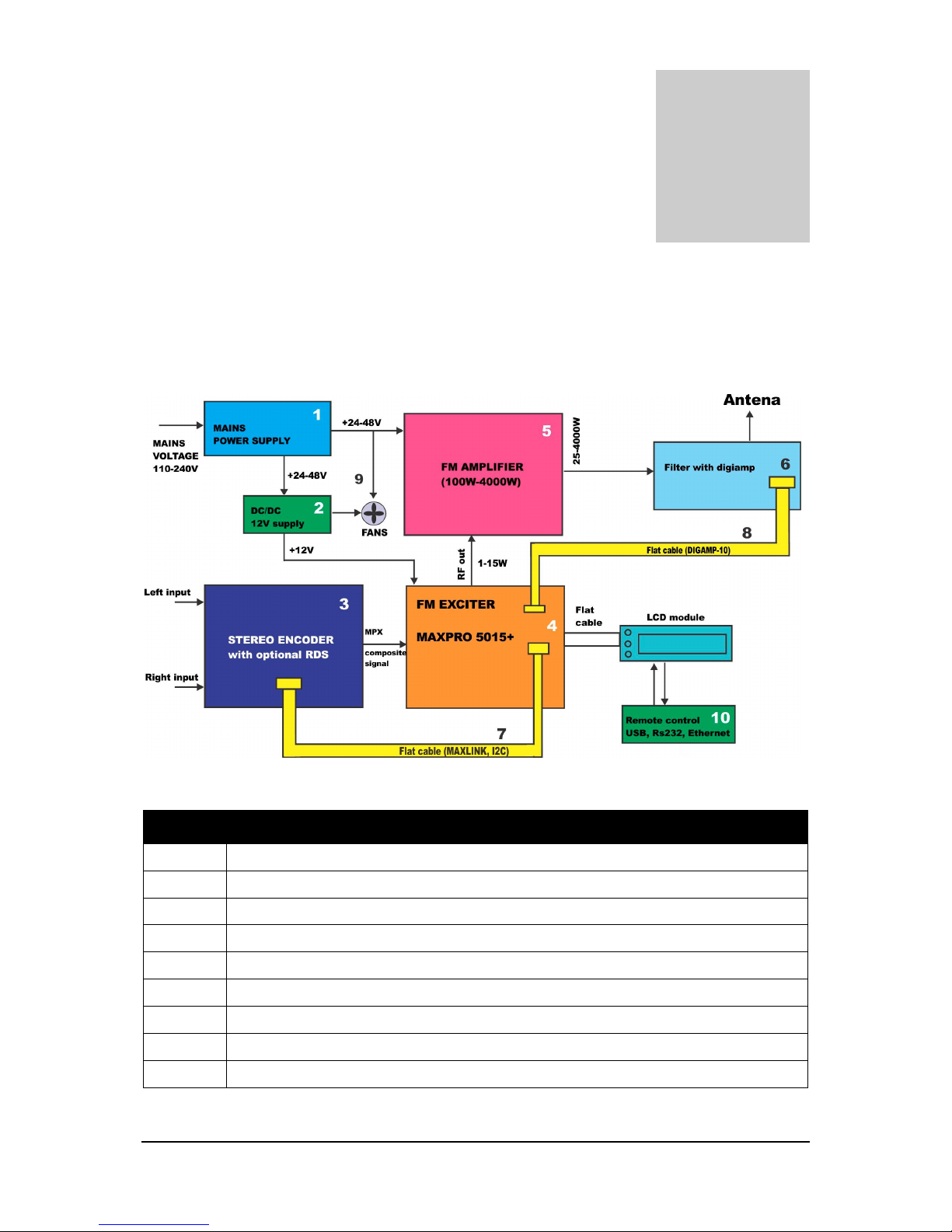
Fig. 3: Block diagram of the CyberMaxFM+ transmitter
Reference Function
1 Mains power supply, universal input 110-240V, IEC jack (same as for PC)
2 DC/DC converter from 48V down to 12V for stereo encoder, FM exciter and fans
3 Stereo encoder with optional RDS
4 FM exciter module, “the brains” of the transmitter
5 FM amplifier module
6 Filter with SWR/PWR sensor, temperature sensor, voltage sensor and current sensor
7, 8 Digiamp and Maxlink interconnect cables for controlling stereo and amplifier.
9 Various fans, there are usually at least two (one for amplifier, one for exciter + stereo)
10 RS232/USB/Ethernet for controlling your RDS encoder and FM transmitter.
Chapter
3
Page 10
Brought to you by PCS Electronics, www.pcs-electronics.com
10
FM Exciter board
CyberMaxFM+ units are all based on our MAXPRO5000+ series FM exciters, note the current revision may differ slightly
from the board in your transmitter as we are constantly fine-tuning the design and making it better.
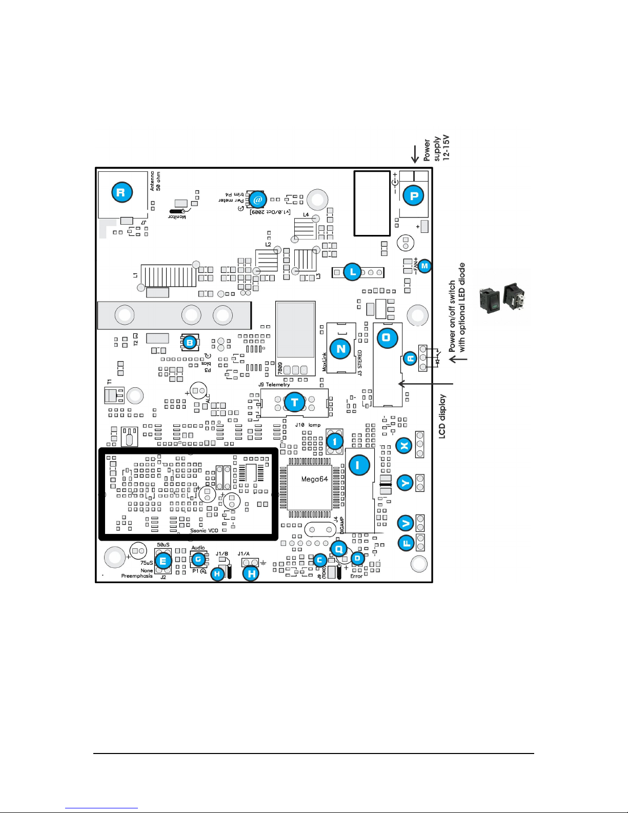
Fig. 4: MAX PRO 5000 series + RF board layout
Page 11

Brought to you by PCS Electronics, www.pcs-electronics.com
11
Ref. Function
A Connect ON/OFF switch here, but you can also just install a jumper. A LED diode can also be connected as
shown on the image; series resistor is on board and is not necessary.
B Output stage bias current. DO NOT change this setting. (Does not exist on new 5015 boards)
C You can connect external TCXO (thermally stabilized reference oscillator). Frequency needs to be 18MHz, TTL.
You will probably have to remove nearby quartz crystal, if you want to use this input.
D Optional ERROR indicator LED can be connected here. This LED is activated when RF output stage is NOT
active. For example, whenever temperature protection is activated, this LED illuminates and RF power is
reduced. This LED is also located on the LCD control module. Important: This LED is also illuminated
whenever you change frequency as the control unit turns RF power off until PLL/VCO tuning is finished. In
such case this does not signal a problem with temperature or SWR.
E Pre-emphasis. Use this jumper to set pre-emphasis. This can either be 50uS (EU and most of the world) or 75uS
(USA). If you plan to connect stereo encoder to the MAXPRO5015+ board, place the jumper in position None
(top - this disables pre-emphasis).
F Power adjustment jumper. Remove this jumper if you want to control power via LCD module. To set output
power via external control voltage (0-5V) apply voltage to header V (J6).
G Audio input sensitivity adjustment.
H Audio input - coaxial cable or 2-pin header.
I Digiamp connector enables easy control of RF amplifiers and mains power supplies that power them. This greatly
simplifies the process of building FM transmitters. You can read more about this connector in appendix.
@ Internal power meter accuracy adjustment. If the internal power display on the LCD is a bit off you can correct its
accuracy with this trimmer, the range of adjustment is very small.
K RF monitor output. This output contains a small sample of output signal, suitable for monitoring RF signal
quality with instruments such as frequency meter, frequency analyzer or modulation monitor.
L You can connect VUMAX-1 led vu-meter unit here, it will show output power and SWR as bar graphs. The 2
remaining bar graphs can be connected to SE5000 DSP+ and will show audio volume.
M Soldering posts for a small 12V fan. Output stage appreciates a bit of air flow, it does not have to be substantial.
As long as the air slowly moves a bit it'll be more than enough so use weakest available FAN. Due to improved
design this fan now spins down completely at low RF power output and our new 40x40x25mm unit is almost
completely inaudible even at highest speed.
N Maxlink connector for easy connection with the SE5000 or SE3000 stereo encoder. This lets you connect and
control both units from the same LCD control units. Our Cyber Max FM+ units use this arrangement. This
connection is now completely solder-free, just plug the connector in and voila, finished. Flat cable that runs
between the units also carries supply voltage for the stereo encoder further reducing required wiring and work.
O LCD control unit, attach your LCD control module here.
P Power supply connector, center is positive. DO NOT use more than 15V.
Q Do not touch unless you understand what this is. Lets you fine-tune the reference frequency. Can be used to set
the unit to any frequency, even though the PLL step is 5KHz. You can for example use this to set the frequency
to 100.001KHz by first using the LCD to set it to 100.000KHz and than using this trimmer to shift it to
100.001.000Hz.
R RF output connection. BNC jack. Use a properly matched FM band antenna. The range and success of your
transmissions will depend primarily upon the quality and position of your antenna so invest your energy and
money into a proper solution. Poor unreliable connections may damage the final transistor.
S 15W - 2.5A fast, 25W 4A fast and 40W – 6.3A fast fuse. Always replace with this type for continued protection
against short-circuit.
Page 12
Brought to you by PCS Electronics, www.pcs-electronics.com
12
T Telemetry connector. All vital signals are available on this 10-pin connector. You can connect a 10-pin connector
at the back of the transmitter and use them to supervise status of the transmitter.
V External control voltage for power adjustment, only works when jumper J5 (F) is removed. Apply external
control voltage (0-5V).
X External power and SWR signal, only use if you are not using digiamp connector (I)
Y Increases sensitivity of external power and SWR meter.
1 Power limit jumper J12, use to limit output power to 2, 4, 6 or 8W (exact value depends on the model)
Description of various elements of the MAX PRO 5015+ FM exciter board
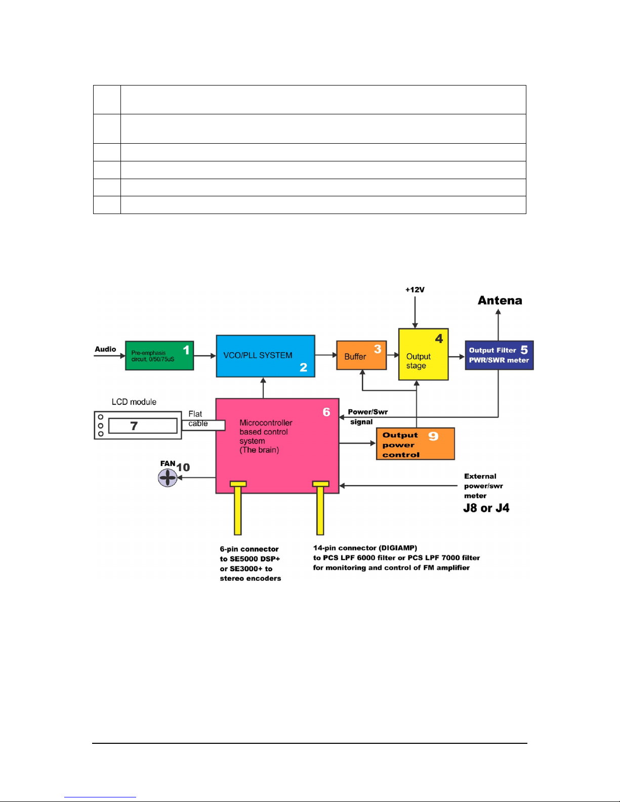
The block diagram of the MAXPRO5000+ series exciter is shown below. It is simplified as the actual block diagram would
be too complex for this manual.
Fig. 5: Block diagram of the MAXPRO5000+ series FM exciter
Stereo encoder board
CyberMaxFM+ units utilize our SE5000 DSP+ (DSP model) or SE2000D+ stereo encoders (analog model)
Page 13
Brought to you by PCS Electronics, www.pcs-electronics.com
13
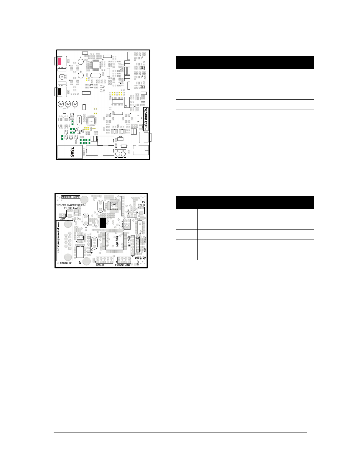
Fig. 6: SE5000 DSP+ stereo encoder board layout
RDS encoder board
CyberMaxFM+ units utilize our RDS MAX 4000+ and RDSMAX4000+ mini RDS encoders
Fig. 7: RDSMAX4000+ rds encoder board layout
Where can I find more info?
Separate extensive manuals for all of the built-in components are available on our website. We have a section in our forum
dedicated to all of the manuals and you can discuss each of the manuals with other forum members here:
http://www.pcs-electronics.com/phpBB2/viewforum.php?f=33
Ref Function
J1-2 Audio Inputs
J3-4 Pre-emphasis selection
J7 MPX out, going to FM exciter audio input
J10 Mode select, don’t install in this configuration
J11 Maxlink 6-pin cable going to MAX PRO 3000+
exciter
J12 Install to reduce pilot level slightly
J14 Stereo/mono selection, do not install jumper here
Ref Function
P1 RDS level
P2 RDS carrier phase relationship to stereo pilot
J11-13 Baud speed selection, leave at default
CLK RDS clock led, should blink at around 1Hz
57KHz PLL lock led, should be off in stereo mode
Page 14

Brought to you by PCS Electronics, www.pcs-electronics.com
14
Before you start
It is recommended that you read this section before you power your unit up for the first time. Let us clear up some basics
you should know about. You will also find some useful tips in our guides and forum at http://www.pcs-electronics.com.
Here is what you need to get your FM transmitter on the air:
Antenna
Preferred type of antenna is affected by several factors, but mostly by desired radiation pattern, space available and your
budget. If you are located in the middle of the area you want to cover you'll need an omni-directional antenna which
transmits equally in all directions. If you are located at the edge of your desired coverage area you can beam the signal into
the target area with a directional antenna. Directional antennas are also practical for point-to-point communications.
Another thing to consider is that directional antennas usually have much higher gain than omni-directional antennas since
the power which is radiated in all directions with omni antenna is concentrated mainly into one direction with directional
antenna. Antennas with more gain thus have narrower beam. A compromise is usually made depending on budget and
space available, higher gain antennas are often bigger and often more expensive.
Once you’ve chosen and installed your antenna there is another thing to consider. You can read more about it in the next
section (So what is this SWR everyone talks about). Before powering up your transmitter on the air you should tune your
antenna to get minimal SWR. This is typically done by adjusting the position of the antenna and any adjustable pieces. Aim
for 2:1 or less. Use low power into the antenna when tuning it up and making adjustments. If you were using full power and
a bit of the antenna came off in your hand the VSWR could be so bad as to blow the final transistor. For the same reason
check the DC continuity of the antenna with an ohmmeter before plugging it in, to be sure it's what it's meant to be, either a
short circuit or an open one, depending on the antenna type. Note you won’t be reading 50 ohms with regular ohm-meter.
For instructions regarding construction of antennas please see our website: http://www.pcs-electronics.com (guides section -
antennas).
Antenna is a crucial part of the system so take special care. It is usually a good idea to place antenna away from your
transmitter, power supply and audio system. Also any transmitter should be in a metal case which shields circuitry from the
radiation of the antenna. If you cannot meet these requirements, you could experience feedback and other RF problems. We
cannot guarantee proper operation of any transmitter/amplifier unless suitable antenna system is used and transmitters are in
ventilated metal enclosure! This applies to any transmitter. Interestingly, strong RF field can make CD players and other
digital devices go crazy. Try placing antenna next to yours and see what happens. Most of the modern audio gear is not RF
shielded – reducing costs is unfortunately the mantra today. This is why keeping antenna away from audio gear is a good
idea, too.
If you are going to place your antenna outside, on your roof, please take care of the grounding. This should be done to
prevent lightning hazard and should be done by a company specializing in lightning protection. You can read more about
lightning protection in the book recommended below or many of the websites (Google up “lightning protection ham radio”
for example).
I hope this basic introduction will not scare you too much, it should be sufficient for the time being although we encourage
you to explore this exciting subject further with the help of a book such as the ARRL Antenna Book:
http://www.amazon.com/exec/obidos/ASIN/0872598047/mightyspiraterad
Chapter
4
Page 15

Brought to you by PCS Electronics, www.pcs-electronics.com
15
So what is this SWR (VSWR) everyone talks about?
SWR is a measure of how well two devices are impedance matched to each other. Typical radio/TV transmission equipment
is designed for 50 ohm load impedance, so we usually use 50 ohm cables and build or buy antennas that are specified for 50
ohm. While most cables have flat impedance over frequency (they measure 50 ohm at all frequencies you are likely to use)
the same is not true of the antennas.
A 1.0:1 VSWR is a perfect match. That means the load impedance is exactly 50 ohms. A 2.0:1 VSWR is obtained when the
load impedance is either 25 ohms or 100 ohms.
Because most transmitters will deliver full power with a load VSWR of up to 2.0:1, this value is usually considered the limit
for acceptable operation. Many prefer to keep their VSWR below that however, but for all practical purposes, it is
unnecessary to spend time or money trying to get much below a VSWR of 1.5:1. The benefits will be hard to measure and
even harder to notice.
On the other hand, coaxial cable losses increase rapidly, for a given frequency of operation, when the antenna VSWR
exceeds 2.0:1. This can even, in some extreme cases, result in the coaxial cable burning, even when running 100 W. Using a
higher grade of cable will definitely improve things, but even high quality coaxial cable becomes very lossy when VSWR
exceeds 3.0:1 at higher HF frequencies (or VHF and higher).
Coaxial cable
Coaxial cable is an electrical cable consisting of a round, insulated conducting wire surrounded by a round, conducting
sheath, usually surrounded by a final insulating layer. The cable is designed to carry a high-frequency or broadband signal,
usually at radio frequencies. Coaxial Cabling is a two conductor closed transmission medium that is often used for the
transmission of RF energy. It yields excellent performance at high frequencies and superior EMI control/shielding when
compared to other types of copper cabling. Coaxial cabling is commonly found in broadcast and networking systems. Most
coaxial cables have a characteristic impedance of either 50 or 75 ohms. The RF industry uses standard type-names for coaxial
cables. The U.S military uses the RG-# or RG-#/U format (probably for "radio grade, universal", but other interpretations
exist).
The common RG-58 from Radio Shack is NOT the best you can do and can eat a lot of your effective power out! Use it
only for short runs. BELDEN makes terrific coaxial cable in various qualities and with very low loss (measured in
dB’s…decibels). 3 dB loss = 1/4 of your signal strength - either lost or gained. Watch out for the correct impedance; RG58,
RG213, H-500 and H-155 have 50 Ohms, RG-59 and RG-6 have 75 Ohms. Most antennas and transmitters including ours
are 50 ohm. Check our website for good coax. Don't buy more than you need to make the long run to your antenna and
don't make up a few "jumpers" to go between your exciter, VSWR meter and your antenna as all you'll do is create higher
SWR and more line losses. H-155 or H500 are good choices! RG-142 with Teflon is recommended for wiring inside
cabinets, for baluns, Wilkinson couplers and everywhere where resistance to heat is required as insulation won’t melt during
soldering or operation.
Mains power supply and mains power cable
Do not underestimate the importance of mains power supply, despite abundance of all kinds of cheap units available today
they unfortunately do not always meet requirements. What you need is a well stabilized DC 15V mains power supply that
can supply at least 2 amps (15W) or more depending on the model (see specifications) of continuous current without
overheating, introducing buzzing, dropping the voltage down to 12V or lower (a classic case) or acting up in other way.
Whenever in doubt please buy our mains power supply. One final note, if you use less than 15V this effectively lowers your
output power. The lower the supply voltage the lower the power.
If you ordered and received our mains power supply (which is recommended) you’ll notice the mains cable is not included,
but can be obtained in any radio/computer/hardware shop at the cost of about 1 US$. It is the type used in your PC for
mains power. Since these cables vary from country to country and we had trouble getting the exact type locally we decided
against including them, especially since finding them is so easy locally.
Audio source with mixer, microphone etc
You need some kind of audio source to drive your transmitter. This will typically be either a computer (just plug the cable
into your sound card outputs, a mixer and a variety of audio sources, such as a microphone, CD player, DAT player, tape
deck, gramophone, MP3 player etc.
Page 16

Brought to you by PCS Electronics, www.pcs-electronics.com
16
Wiring everything together
Wiring things up and first power-up
Wiring the CyberMaxFM+ is easy, just make sure you read the previous chapter first and setup antenna and coaxial cable
correctly. Than proceed with the following:
- Erect antenna tower and install antenna securely. Make sure your antenna is well away from any metal objects. Ensure your
antenna tower is grounded securely.
- Connect one end of your 50ohm coaxial cable to the antenna. If you have SWR analyzer you can now verify SWR of your
antenna. If your antenna is already tuned connect the other end of coaxial cable to the antenna connector (BNC) at the back
of the transmitter. If you have SWR/POWER meter, you can wire that one inline between antenna and transmitter as well.
Make sure the SWR meter supports the frequency band required (87-108MHz). Ensure all connectors are firmly secured and
antenna is mounted securely.
- While making sure power switch is off connect mains power cable into the mains power supply and connect mains power
supply into the back of the transmitter.
- Inspect all cables quickly again and make sure everything is secure.
- Turn on a radio receiver and set it to your intended transmitter frequency.
- Flip the POWER switch and wait for the unit to turn on. Enter the menu system by pressing the bottom key (Menu)
repeatedly and look for the <RF power> menu item. Now set desired output power with the UP/DOWN keys. For tuning
and testing use around 25% of full power. Press Menu again to exit back to main display. Now you can use the
UP/DOWN keys to set the desired frequency of operation. Wait a few seconds for the red LED diode to turn off. Your
radio should now mute since you did not connect any audio sources yet.
- Observe SWR and output power. If everything seems ok enter <RF power> menu on your amplifier again. Increase power
to full.
- You can now connect audio sources of choice and verify audio performance. You should not sound louder than other
stations, in fact unless you have an expensive high performance software or hardware sound processor you should sound
quieter than other stations.
Chapter
5
Page 17

Brought to you by PCS Electronics, www.pcs-electronics.com
17
Using the CyberMaxFM+ series transmitter
Basically there are three push-buttons available for the menu system; UP, DOWN and MENU. By pushing UP or
DOWN you get a shift of frequency in corresponding direction. Hold any of these keys for a few seconds and the jumps
will increase to 500 KHz. The new frequency is saved automatically. The third button (MENU) gives you an option to
select and setup many of the options and DSP functions of this unit.
Lcd control module menu system: Power and DSP functions
The UP and DOWN keys are used to change parameter values. In normal mode the LCD simply shows the frequency and
power or whatever view you select. Menu key can be used to enter the menu mode, repeatedly pressing this key brings up
the following menus: <RF POWER>, <STEREO MODE>, <VIEW SELECT>, <TREBLE>, <BASS>,
<COMPRESSION>, <THRESHOLD>, <ATTACK>, <DECAY>, <INTEGRATION>, <LCD CONTRAST>,
<RIGHT CH VOL>, <LEFT CH VOL>, <PLL STEP>, <RF EQ>, <FIRMWARE VER>, <PWR/SWR METER>,
<TEMP ALARM>, <SWR ALARM>, <BAND SELECT>, and <RF AMP CONTROL>. Pressing the UP or DOWN
key selects the desired parameter and allows you to modify its value. Another press on the MENU key and you’re back to
the normal mode. Note that all these settings except power and frequency are already set as they should be so changing them
should not be necessary and is not recommended.
Changing frequency
Simply press the UP/DOWN button to change frequency. Depending on PLL STEP setting your frequency will go down in
5/10/25/50/100/200KHz steps. If you keep pressing a key for a while the PLL STEP switches to fast tuning mode and
jumps in 500KHz steps.
Note: Frequency changes also when you select a view type which does not show frequency, such as UPTIME.
<RF POWER>
This setting allows you to set output power. Select desired power with the UP/DOWN keys and press MENU key to exit
the menu system and return to normal operation. Selected power is displayed on the LCD as a line of bars. Think of this
setting as an accelerator (gas) pedal in your car. Think of the power in watts that is shown on the LCD as the speed meter in
your car. Depending on the road going uphill or downhill speed meter will show different values even if your accelerator
pedal is fixed in the same position. If you go downhill your speed will be greater with same amount of gas pedal. Likewise
here your supply voltage can affect the actual output power slightly.
<STEREO MODE>
You can set your transmitter to MONO or STEREO here.
Chapter
6
Page 18
Brought to you by PCS Electronics, www.pcs-electronics.com
18
<VIEW SELECT>
CyberMaxFM+ is capable of displaying a number of various parameters. Since the LCD real-estate is limited to 2x16
characters we prepared a number of pre-programmed views that only show a selected number of parameters. At the time of
writing these views were available:
- [Freq+Mode+Pwr] – This view shows frequency, mono/stereo mode and output power
- [Fr+Mode+Te+Ue] – This view shows frequency, mono/stereo mode, exciter temperature and exciter supply voltage
- [Po+Pr+Uamp+Ta] – This view shows output power, reflected power, amplifier supply voltage and amplifier temperature
(if used)
- [Audio Level] – This view shows audio level bar graph. For this to work you the W solder bridge on the LCD module
needs to be closed-soldered.
- [Uptime D:H:M] – This view shows how long the transmitter has been operating without mains power going out. It is
sometimes useful in diagnosing mains power failures.
- [Auto Scroll]D – This is the default view, it shows each of the above listed views for a short while and than moves on to
the next in an endless loop. This way you can see all the relevant parameters without having to go through the menu system
to change the view type, You just have to wait a few seconds for the view to change.
<TREBLE> and <BASS> (only with DSP stereo encoders)
This option allows you to set the amount of TREBLE and BASS in your audio. Recommended values are marked with (D).
Fig. 8: Setting treble
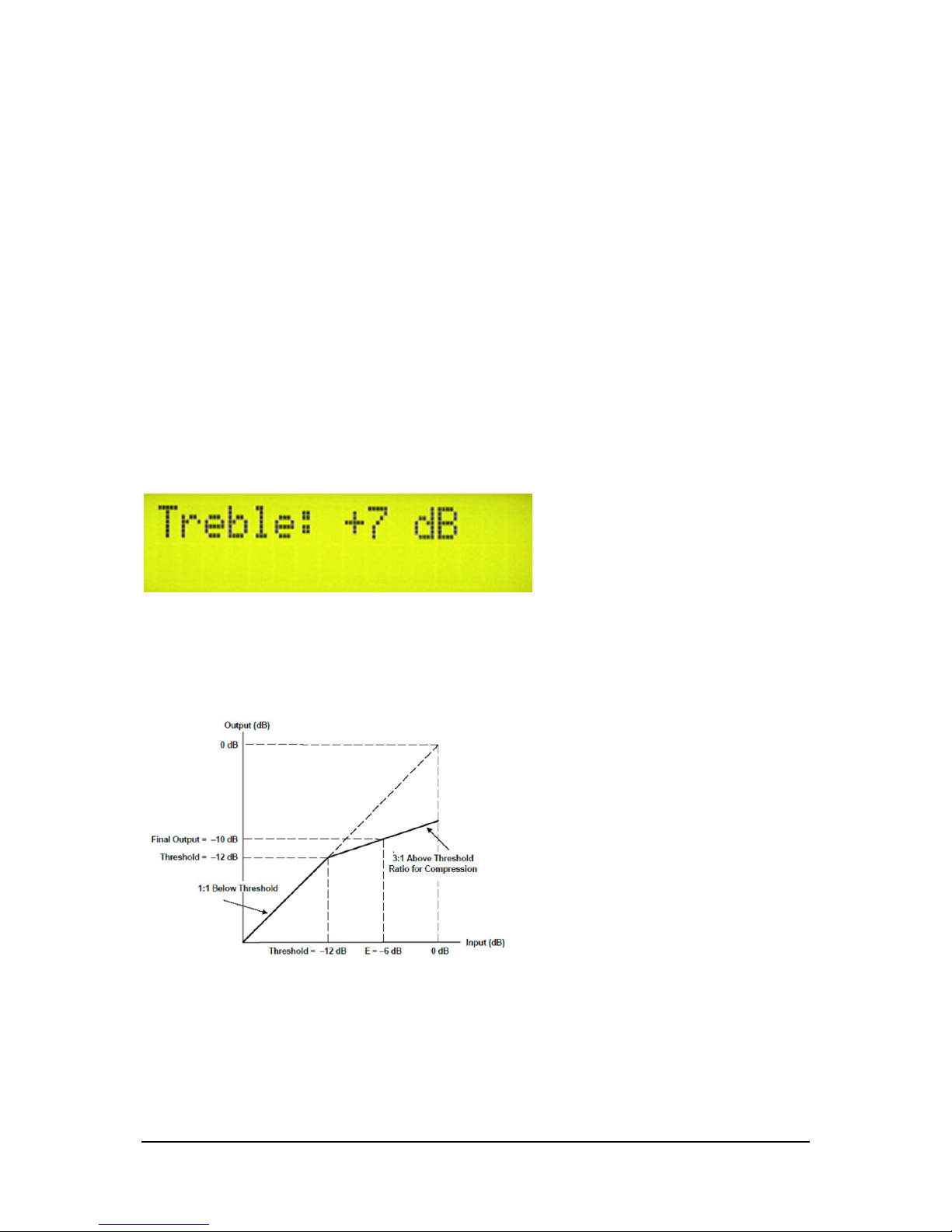
Compressor Settings (only with DSP stereo encoders)
A number of MENU settings control the operation of the compressor. Lets assume that the audio signal enters the
transmitter at some low level. Compressor does nothing to the signal until at one point as the input signal increases the signal
reaches the compression threshold. Digital signal processor starts compressing the signal beyond that point. The higher the
compression ratio the higher the compression. For example, compression ratio of 1:∞ would in effect be a limiter.
Fig. 9: Explanation of the compressor settings
Page 19

Brought to you by PCS Electronics, www.pcs-electronics.com
19
Fig. 10: Setting the compression level
Fig. 11: Setting the compression threshold
Fig. 12: Setting the attack time, this is the time between the input signal and the actual response of the compressor
Fig. 13: Setting the decay time, this is the time the compressor needs to respond after the input signal falls back to normal level (below threshold).
Fig. 14: Setting the integration interval, this is the time the DSP evaluates the signal to establish whether it should respond or not
Integration interval determines the energy needed to trip the compressor. In simple words; it determines how long the audio
needs to be loud for the compressor to respond by reducing the gain. This is not to be confused with attack time. Attack
time of 50ms means the compressor will respond in 50ms after the signal spike is detected, regardless of duration of that
spike, even if it is just a very short event. With longer integration interval, on the other hand, compressor only responds if a
long spike or a substantial number of spikes is detected (meaning more signal energy).
<LCD CONTRAST>
Select for the best visibility. Contrast is slightly affected by ambient temperature and you can adapt it to your needs here.
Fig. 15: Changing contrast
Left and right channel volume (only with DSP stereo encoders)
This option allows you to precisely adjust the input sensitivity of both audio channels. This is very useful when your audio source has either too
high or too low output level.
Page 20

Brought to you by PCS Electronics, www.pcs-electronics.com
20
Fig. 16: Changing right input channel gain
<PLL STEP>
Frequency can normally be adjusted in smallest steps of 5KHz or larger steps of 10KHZ, 25KHz, 50KHz or 100KHz. We
recommend you to select 100KHz as this lets you change frequency fast and there is rarely need for fine tuning. However,
you can enter this menu and select a PLL step of 5KHz for example and take advantage of these small steps.
<FIRMWARE VER>
This option allows you to display current LCD module firmware version.
Fig. 17: Firmware version
<CURRENT ALARM>
You can set the sensitivity of amplifier current alarm here. We recommend you set these according to your amplifier. This
alarm only works if you use PCS LPF 6000 or PCS LPF 5000 filters with current sensor. Current meter accuracy is not very
high at this time.
<TEMP ALARM>
You can set the sensitivity of temperature alarm here. We recommend you set these to 75 degrees Celsius. A properly
installed unit with a tiny fan will typically run at 55 degrees C at maximum output power. This alarm applies to externally
sensed temperature (PCS LPF 6000/7000 or ControlMini2), if you are using external PWR/SWR METER.
<SWR ALARM>
You can set the sensitivity of software driven SWR alarm here.
<U AMP ALARM>
You can set the sensitivity of amplifier supply voltage alarm here. We recommend you set these according to your amplifier.
Usually this is around 50V. This alarm only works if you use PCS LPF 5000/6000/7000 filters with voltage sensor.
<BAND SELECT>
MAXPRO5015+ supports one band, if you want us to modify design for another frequency please let us know:
- [87.5-108MHz]D – This is default band, used in most of the world. MAXPRO5015+ works perfectly across the entire
band. Changing this setting can lead to serious damage so it can only be changed in our testing lab.
<RF AMP CONTROL>
This menu option lets you choose how the MAX PRO 5015+ controls the amplifier. Please leave this setting at default value
“(D).
Page 21

Brought to you by PCS Electronics, www.pcs-electronics.com
21
<RF POWER ALC>
This menu option is useful for situations where MAX PRO 5000 drives a pallet or other FM amplifier. It is possible to set a
limit power level (for example 500W) and exciter will reduce its output power if needed to prevent overdriving. This is a very
useful feature when you are for example building a 500W, 1000W or stronger FM transmitter, it ensures constant power
across the band without overdriving. Changing this setting can lead to serious damage so it can only be changed in
our testing lab.
Page 22

Brought to you by PCS Electronics, www.pcs-electronics.com
22
DESCRIPTION OF WINDOWS CONTROL PROGRAM
Setup
COM port
Select correct COM port here. Usually this would be COM1.
Baud rate is selected automatically according to the selected FM transmitter type.
Communication test tool
Use this feature to find correct settings easily. Try different settings and check them by clicking the button.
Autoscan
Use this feature to find correct settings even more easily. Just click it and wait to program find the connected
transmitter by itself.
Chapter
6
Page 23

Brought to you by PCS Electronics, www.pcs-electronics.com
23
FM TX main
FM transmitter type
Select your FM transmitter type.
FM transmitter frequency
Set the frequency by 0.5 or 0.05MHz step.
Transmitter output power
Set the desired output power.
Stereo/Mono
Select audio mode.
Audio input level
Select audio gain for left and right channel separately.
Bass and Treble
Select boost level for Bass and Treble.
Page 24

Brought to you by PCS Electronics, www.pcs-electronics.com
24
Audio Compressor Settings (only with DSP stereo encoders)
These are settings which control the operation of the compressor. Lets assume that the audio signal enters the
transmitter at some low level. Compressor does nothing to the signal until at one point as the input signal increases
the signal reaches the compression threshold. Digital signal processor starts compressing the signal beyond that
point. The higher the compression ratio the higher the compression. For example, compression ratio of 1:1 would in
effect be a limiter.
Attack: Set the attack time, this is the time between the input signal and the actual response of the compressor.
Decay: Set the decay time, this is the time the compressor needs to respond after the input signal falls back to
normal level (below threshold).
Interval: Set the integration interval, this is the time the DSP evaluates the signal to establish whether it should
respond or not.
Integration interval determines the energy needed to trip the compressor. In simple words; it determines how long
the audio needs to be loud for the compressor to respond by reducing the gain. This is not to be confused with
attack time. Attack time of 50ms means the compressor will respond in 50ms after the signal spike is detected,
regardless of duration of that spike, even if it is just a very short event. With longer integration interval, on the other
hand, compressor only responds if a long spike or a substantial number of spikes is detected (meaning more signal
energy).
Threshold: Set the compression threshold.
Compression: Set the compression level.
Page 25

Brought to you by PCS Electronics, www.pcs-electronics.com
25
FM TX alarms
Here many operating parameters can be observed including alarms. Threshold values of alarms can be set too.
Read TX
Click this button to get the current status of your hardware.
Auto read TX
Check this box to activate automatic continous hardware status reading.
Page 26

Brought to you by PCS Electronics, www.pcs-electronics.com
26
PI, PTY...
PI code
This information consists of a code enabling the receiver to distinguish between countries, areas in which the same
programme is transmitted, and the identification of the programme itself. The code is not intended for direct display
and is assigned to each individual radio programme, to enable it to be distinguished from all other programmes. One
important application of this information would be to enable the receiver to search automatically for an alternative
frequency in case of bad reception of the programme to which the receiver is tuned; the criteria for the change-over
to the new frequency would be the presence of a better signal having the same Programme Identification code.
TP/TA flag
TP is a flag to indicate that the tuned program carries traffic announcements. The TP flag must only be set on
programs which dynamically switch on the TA identification during traffic announcements. The signal shall be taken
into account during automatic search tuning, so I recommend to turn this flag on even though you don't transmit
any traffic announcements.
Program type PTY
This is an identification number to be transmitted with each program item and which is intended to specify the
current Program type within 31 possibilities. This code could be used for search tuning. The code will, moreover,
enable suitable receivers and recorders to be pre-set to respond only to program items of the desired type. The last
number, i.e. 31, is reserved for an alarm identification which is intended to switch on the audio signal when a receiver
is operated in a waiting reception mode.
Music/Speech
This is a two-state signal to provide information on whether music or speech is being broadcast. The signal would
permit receivers to be equipped with two separate volume controls, one for music and one for speech, so that the
listener could adjust the balance between them to suit his individual listening habits.
AF - Alternative Frequncies
The list of alternative frequencies gives information on the various transmitters broadcasting the same program in
the same or adjacent reception areas. This facility is particularly useful in the case of car and portable radios. When
the PI code indicates local coverage-area, i.e. only one frequency is used, AF list may contain this frequency.
Page 27

Brought to you by PCS Electronics, www.pcs-electronics.com
27
PS0
PS
This is the label of the program service consisting of not more than eight alphanumeric characters, which is displayed
by RDS receivers in order to inform the listener what program service is being broadcast by the station to which the
receiver is tuned.
If you want to use just one PS setting please set delay for all others to 0.
You can select delay for each of the PS labels. Note that setting a 0 disables associated PI.
Labels will start at the start of the list once they reach the last defined PS label.
Do not exagerate, fast changing PI labels can compromise driver safety!
More information about PS feature
This is the most interesting feature for 99% of customers out there so we will dedicate a bit more time to it. RDS
standard provides for a 8-character PS string which is used to identify radio station and is displayed by RDS-enabled
radio receivers. Some countries prohibit changing this text dynamically, but others don't. Whatever your decision
may be, RDSMAX supports either static or dynamic PS. It is best to check with the local authorities before setting
up the RDS encoder.
The mechanism for handling dynamic (or static) PS text is best demonstrated by the following example:
Imagine a train traveling in a round trip involving 100 train stations. The train starts on station 00 (PS00) and goes
through stations 01, 02…. until it passes through station 99 and finally returns to station 00. Every time a train stops
at the station it sends the message back to the headquoters (PS text shown on RDS receiver). The amount of time
the train stays at the station (delay - PD00 to PD99) varies and can be from 0 minutes (train does not stop) to 9
minutes. I hope this little analogy has illustrated the process. You have 100 8-character strings (PS00 to PS99) which
are displayed one after the other until the entire loop repeats itself. You can define how long each of these strings is
displayed, the parameter which defines this is PD (PD00 to PD99).
Example: If you wish to just have one static PS, set all delays to 0 and set just PD00 to 1. Than set PS00 to desired
statis PS, which will be displayed indefinitely.
Page 28

Brought to you by PCS Electronics, www.pcs-electronics.com
28
PS1
Next level of PS messages.
PS2
Last level of PS messages.
Page 29

Brought to you by PCS Electronics, www.pcs-electronics.com
29
TIME, MSG...
Computer time and date
Select to Synchronize RDS RTC (Real Time Clock) with current PC clock.
External switchable messages
To activate these messages attach 8 switches to header J10 (EXTMSG).
These switches must be going to ground from each of the 8 pins and are activated when you ground the
corresponding pin.
Message is scrolled, if larger than 8 characters.
Page 30

Brought to you by PCS Electronics, www.pcs-electronics.com
30
AUTO PS, RT...
Auto PS and RT update is another hugely popular feature. Basically you can take the song title from Winamp or
another program via text file. Winamp must be setup to write its song info into a text file, this is done with TitleSpy
plugin. Most other playback programs can easily be setup to write song info into a text file. You can use this info to
update PS or RT text. PS text is limited to 8 characters so the entire song title can either be scrolled or split into 8character blocks. You can set the speed of scrolling on the panel above. You can also insert DATE at the end of the
scrolling block. A really popular and nifty feature indeed. This feature requires your PC to be connected to the RDS
encoder at all times during music playback.
Auto update PS from txt file
This mode makes it possible to have the PS updated automatically. A number of very usefull features make this
mode extremely usefull. It is possible to insert time, date or song name from external file. This external file can be
updated via Winamp or any other program.
If you want to collect data from Winamp (MP3 ID tag, song name) please use winamp plugin called VtitleSpy. This
little program was shipped with our driver, you will find it in the RDS MAX installation folder. Install it and
configure it to output winamp song info into your text file and than set RDS MAX driver to read song name from
that file. Also make sure you setup VtitleSpy plugin to limit song name to 64 characters.
Auto update RT from txt file
This is another popular feature, RDS allows for 64-character text string to be displayed on the receiver. However this
feature is rarely used as you need to press a button to display it (PS is always displayed by default). Another "nail in
RTs' coffin" is the fact that typical receiver only displays a maximum of 8-characters at a time meaning the message
needs to be scrolled. However popular or unpopular it may be, we support it.
The field at the top (RT) shows the currently active RT message
The auto update RT field makes it possible to collect the RT from any text file. In order to pick RT from a text file
select the text file with the browse button and enable auto update by selecting the Yes option. RDS MAX driver will
check the file once every second and update the encoder automatically, if it detects any changes of the text file.
If you want to collect data from Winamp (MP3 ID tag, song name) please use winamp plugin called VtitleSpy. This
little program was shipped with our driver, you will find it in the RDS MAX installation folder. Install it and
configure it to output winamp song info into your text file and than set RDS MAX driver to read song name from
that file. Also make sure you setup VtitleSpy plugin to limit song name to 64 characters.
Page 31

Brought to you by PCS Electronics, www.pcs-electronics.com
31
About
Firmware version
Here can be found firmware version of your hardware. At least one TX read must be proceeded to get the proper firmware version.
Page 32

Brought to you by PCS Electronics, www.pcs-electronics.com
32
Common controls
These are common controls belonging to all program tabs.
Move to tray
Click Move to tray to move this program into taskbar.
Check To tray at start checkbox to start the program minimized in system
tray.
Preview
This window shows PS and RT preview.
Select desired preview type by clicking appropriate radio button.
RDS active
Check this box to activate RDS features.
Send settings
Send settings and Send RT and PS buttons may change their appearance and
accessibility according to currently active tab.
Use Send settings to send parameter values + PS00 and RT to RDS encoder.
Use Send RT and PS to send all PS and RT parameters to RDS encoder.
Shut down TX at exit
Check this box to automatically reduce transmitting power to 0 when exiting
the program.
Send settings at start
Check this box to automatically send TX settings at starting the program.
This may come handy when Shutdown TX at exit is activated to
automatically raise TX power when next time starting the program.
Audio histogram
Every time the transmitter status is read, a new audio level value is added at the histogram. Status may be read manually (by
clicking Read TX button) or automatically (by checking Auto TX read checkbox). Levels above 80% are marked in red
colour.
Status window
Some communication activities can be observed here.
Page 33

Brought to you by PCS Electronics, www.pcs-electronics.com
33
Scheduler
Built-in scheduler allows to user determine automatic switching of transmitting power and frequency according to
predefined scheme. Schemes can be defined on daily or weekly basis. To accomplish this task the PC must be
connected to the transmitter and the program must be running all the time.
Up to 20 controlling lines can be entered into list box. Each line defines transmitting power, frequency and switching
time.
Put a tick at the beggining of each line to make that line active. There can be many lines active if desired.
It is recommended to be careful while entering lines not to make time-overlapping lines active at the same time.
Example: if you define a line on daily basis and at the same time another weekly based line is active the results may
be unpredictable.
You can always enter many lines and then decide which of them should be momentarily active by putting ticks into
checkboxes.
Enable
Check this box to make the scheduler active in general.
Add...
Click Add... button to open Add form to add a new line into list box.
Edit
Select desired line first, then click Edit to open Edit form.
Remove
Select desired line first, then click Remove to delete it.
Page 34

Brought to you by PCS Electronics, www.pcs-electronics.com
34
Add form
Add form allows you to enter the following parameters:
transmitter frequency transmitter power repetition mode; it can be Daily or Weekly switching time
Daily repetition mode switches every day at the same time. To make sense, at least two daily based lines should be active at the same time.
Weekly repetition mode allows individually selection of days in the week.
Add or Modify
Click this button to accept changes. In the case of adding lines more lines can be entered subsequently.
Close or Cancel
Click this button to finish adding lines or to cancel editing.
Page 35

Brought to you by PCS Electronics, www.pcs-electronics.com
35
Troubleshooting
We hope you’ll never get to this step. We all know bad things happen but do not despair! Cybermax FM+ is protected with a
fuse, SWR and TEMP protection. Fuse is the first thing to check. Make sure your coaxial cable leading to the transmitter or
antenna is not shorted or open. Next check the troubleshooting table on the next page. If you have problems you cannot
solve yourself, please see our website for contact information and support resources in our forum.
Fig 18: So, do you think you can handle it? We think you sure can!
Chapter
7
Page 36

Brought to you by PCS Electronics, www.pcs-electronics.com
36
PROBLEM DESCRIPTION POSSIBLE SOLUTIONS
Everything appears normal, but
there is no RF power
1. Wait a few more seconds, MAX PRO 5000 series exciters need about 8 seconds to get their
power to full, power is slowly ramped up.
2. Maybe one of the alarms was triggered and power was reduced, try to power off and power
back on, whenever an alarm is triggered power may be reduced until you power off and back
on
RF output power is too low 1. Maybe one of the alarms was triggered and power was reduced, try to power off and power
back on, whenever an alarm is triggered power may be reduced until you power off and back
on
2. Find out which alarm was triggered, maybe your unit is over-heating or your antenna (SWR)
may be way off. Let the unit cool off and ensure proper cooling in the future. Perhaps you
adjusted TEMP ALARM or another alarm too low, set it slightly higher.
LCD display keeps showing
TEMP/SWR error warning
1. Unit is probably over-heating or your antenna is faulty. Let the unit cool off and ensure
proper cooling in the future. Perhaps you adjusted TEMP ALARM too low, set it slightly
higher.
2. It is very likely that your antenna is not working correctly, check cable and check SWR. You
may need to adjust SWR ALARM slightly higher (but first make sure your antenna and cable
are OK).
Audio too quiet/loud 1. Open or close the modulation trimmer on MAX PRO 5015+ exciter board a bit.
2. Increase or decrease level on your audio source a little bit, start using software or hardware
compressor. If increasing leads to distortion you may need to open the trimmer on MAX
PRO 5015 exciter board
3. Get a compressor, you can’t sound as loud as best commercial stations unless you get a
compressor, they are all using one, this can either be a software program or even better a
dedicated hardware, check our website for studio equipment. Compressor keeps your audio
“pumped up” while preventing over-modulation (distortion).
Audio too loud 1. Close the modulation trimmer on MAX PRO 5015+ exciter board a little bit.
2. Get a compressor, you can’t sound as loud as best commercial stations unless you get a
compressor, they are all using one, this can either be a software program or even better a
dedicated hardware, check our website for studio equipment. Compressor keeps your audio
“pumped up” while preventing over-modulation (distortion).
Unit blows fuses and draws
excessive current
You have probably burned the output transistor. It is time to contact service support; you may
have to replace a final transistor.
Power supply is blinking Probably the same thing as above. Blinking power supply means its protection is shutting it off
and back on, probably due to excessive current draw caused by burned final.
Audio distortion on high peaks,
for example on “s” sound.
Your audio input level is slightly too high, reduce input audio level slightly at your audio
source. Use some kind of compressor to remove over-modulation peaks.
There is HUM in audio - Move antenna as far away from the transmitter and audio gear as possible
- Use balanced audio inputs (XLR audio connectors) rather than RCA
- Make sure SWR is low and that all equipment is grounded.
- Keep audio cables short and away from antenna and RF coaxial cable
- Form a coil from coaxial cable going to the antenna, make a few turns. This stops RF
currents that might be flowing on the outer braid of the coaxial cable.
Page 37

Brought to you by PCS Electronics, www.pcs-electronics.com
37
Appendix A: DIY antenna and improvement tips
Simple GP antenna design
You can build an inexpensive 1/4 wave antenna from 1 so-239 chassis mount rf connector and 5 - 3' bronze welding rods,
cut to the proper length. We don’t recommend this for more than 150W and even that only when you tune the antenna first
with SWR meter. Here is how it looks:
Fig. 19: »Do it yourself« GP antenna
For other antenna designs check our web site here: http://www.pcs-electronics.com/guide_antenna.php
Some more improvement tips
Think about purchasing SWR meter to tune and align your antenna. A good antenna system is extremely important and can
make up for a lot of power. For a suitable SWR meter check:
http://www.pcs-electronics.com/cn101l-daiwa-power-meter-p-347.html
If you can’t get much range with your homebrew antenna, have a look at these:
http://www.pcs-electronics.com/antennas-c-38.html
Appendix
A
If you have a SWR meter,
leave a bit longer radiator
and adjust it later by
cutting to achieve
minimum SWR.
Most designs on the web don't compensate for the fact
that GP antennas are not wideband antennas. Here is a
Freq/element length chart for this simple GP antenna, all
element lengths are in millimeters:
Frequency Radiator - B Radials - A
108MHZ 660mm 693mm
104MHz 684mm 720mm
100MHz 713mm 749mm
90MHz 792mm 819mm
Page 38

Brought to you by PCS Electronics, www.pcs-electronics.com
38
Appendix B: General tips for setting up transmitters
Typical FM transmitter setups
Below are several of the typical broadcasting systems that can be encountered worldwide.
Fig. 20: Typical broadcasting systems
Lets look at system A first. It consists of audio source (mixer, microphones, CD players and a PC), FM exciter with
integrated RDS and stereo encoder (such as our CyberMaxFM+ units from 15W-300W) and antenna. Note antenna in this
system is located in the same location as the transmitter and studio, typically it would be placed on a small tower or a pole at
the top of the building with studio. Disadvantage of this system is that you have to keep studio, transmitter and antenna
close. Now you usually can’t place studio on the top of a mountain for practical reasons so this limits your range. This is a
typical small community radio with output powers of up to 300-500W.
System B is very similar to system A, but operators have decided to add an additional amplifier to boost the range. Such
stations can go into kilowatts, but they are starting to hit another speed limit. Since the studio is typically located in a town,
high RF powers aren’t desirable due to interference with other services and safety regulations. So range is still limited
compared to system C stations.
System C is radically different in one respect. Antenna and transmitter are no longer located at the same place with the
studio. To accomplish this the two audio channels are first combined with stereo processor. Resulting MPX signal is than
passed to the STL wireless link transmitter (STL=Studio Transmitter Link). Up in the mountains is a STL wireless link
receiver that receives the signal from the studio and passes I to the exciter. In this case exciter does not need to be stereo
anymore since composite MPX signal is passed to its MPX input (all mono transmitters have this input). Such exciters can
than optionally drive big amplifiers with powers going into tens of KW with maximum range.
You can check our amplifiers here: http://www.pcs-electronics.com/fm-amplifiers-c-41.html
You can check our wireless STL links here: http://www.pcs-electronics.com/wireless-audio-links-c-42.html
Appendix
B
Page 39

Brought to you by PCS Electronics, www.pcs-electronics.com
39
Typical FM broadcasting antenna setups
Below are several of the typical broadcasting antenna systems that can be encountered worldwide.
Fig. 21: Typical antenna setups
Lets look at system A first. It’s a simple vertical dipole antenna, mounted on a pole. The gain of this antenna is 0dBd and if
we assume that the coaxial cable does not have any losses the ERP of this system equals transmitter power. For example, a
1KW transmitter with this antenna system and perfect coaxial cable (losses=0) would have ERP of 1000W. Radiation
pattern of this system is more-less omni-directional but since the metal pole holding the antenna blocks the signal there is a
null of signal exactly on the opposite side of the pole.
System B has two simple dipole antennas mounted on a pole. The gain of this antenna is slightly less than 3dBd (due to
losses in harness – splitter). If we assume that the coaxial cable does not have any losses the ERP of this system equals
double transmitter power. For example, a 1KW transmitter with this antenna system and perfect coaxial cable (losses=0)
would have ERP of 2000W. Note the antennas are mounted on the opposite sides of the pole to help make radiation pattern
as omni-directional as possible.
System C has four simple vertical dipole antennas mounted on a pole. The gain of this antenna is slightly less than 6dBd
(due to losses in harness – splitter). If we assume that the coaxial cable does not have any losses the ERP of this system
equals 4x transmitter power. For example, a 1KW transmitter with this antenna system and perfect coaxial cable (losses=0)
would have ERP of 4000W. Note the antennas are mounted at an angle of 90 degrees between each other to help make
radiation pattern as omni-directional as possible.
System C has theoretically double the range of the System A although in practice it takes 4-6x increase of power to double
the range. 4x increase of power is equal to 6dB of gain. And you get 3dB of gain by doubling the number of dipoles. So to
upgrade system C to 9dBd you’d need 8 dipoles. And for 12dBd you’d need 16 dipoles. 16 dipoles would in theory increase
your range 4x compared to a single dipole. In practice there would be some losses in combining so many dipoles. You can
use circular dipoles in very similar configurations.
Page 40

Brought to you by PCS Electronics, www.pcs-electronics.com
40
Wiring antennas in multi-bay configurations
We have observed typical multi-dipole (called multi-bay) antenna configurations on the previous page. However there are
some things to keep in mind.
Fig. 22: Wiring multi-bay antennas
Look at the diagram above. This is a simple system with two dipole antennas and a 2-way coaxial splitter (harness). This
splitter is made from sections of coaxial cable with such impedance and length which ensure perfect match at specific
frequency. Do not attempt to assemble from regular 50-ohm coaxial cable. What is important here is that the two sections of
coaxial cable going from antenna to the splitter should be of exact equal length. These two sections are shown in black. The
same rule applies for system with more dipoles. It is also possible to have cables of different lengths, but you have to know
velocity factor of the cable so we have omitted this for simplicity reasons. If you want more info please contact our technical
staff.
Page 41

Brought to you by PCS Electronics, www.pcs-electronics.com
41
Appendix C – Attaching external stereo processor
You may prefer to use another external stereo sound processor. Usually this could be for two reasons, either because you
obtained a professional grade high-performance stereo sound processor or because you are using a wireless link. Here is
what your system would look like for wireless studio-transmitter link:
Fig. 23: Using external stereo/rds processor for wireless link
Fig. 23: Using external professional stereo/rds processor
It is important that you set the CyberMaxFM+ unit in these two systems to MONO. This ensures that the two stereo
encoders are not interfering with each other. Next you can connect external stereo encoder or wireless link receiver to the
MPXin input at the back of the unit. If you get stuck or need our advice please contact our technical department.
Appendix
C
Page 42

Brought to you by PCS Electronics, www.pcs-electronics.com
42
Appendix D – PC remote control via USB and RS232
Software installation
Download the latest CyberMaxFM driver from our website. You can find it here:
http://www.pcs-electronics.com/phpBB2/viewtopic.php?t=2268
Once you have the driver run the setup file and install the program on your computer. This process is very straight-forward
and should only take a few minutes. Wait for the installation to complete and click Finish when done.
Fig. 24: Setup is about to start
Once the installation is done you are ready to start the program. You are now ready to establish connection with the
CYBERMAXFM+ and configure all the parameters.
Fig. 25: CYBERMAXFM+ application program
Appendix
D
Page 43

Brought to you by PCS Electronics, www.pcs-electronics.com
43
As you can see this program lets you control all parameters of your FM exciter board. It also lets you read all of the available
information, such as output power, temperature, frequency, uptime etc.
Configuring communications port
The only setup required is minimal. Start the CyberMaxFM+ program, the icon should now be on the desktop. Now click
File and setup. The following window will open. You can set COM port manually or you can use Autoscan feature. Make
sure to set FM Transmitter type correctly and it is turned On! A short guide for manual settings: If you are using USB make
sure to set COM port to 5! When using RS232 please set COM port to 1 or 2. These settings are usually correct. If not, we
will explain the installation and setup process for USB control cable in more detail below. You can use Communication test
tool to approve the selected COM port.
Fig. 26: Set COM port to 1 for RS232 IO board
Installing USB driver (only for USB IO board)
Unzip the archive_usb2comport_driver.zip file that you downloaded off our website here: http://www.pcselectronics.com/phpBB2/viewtopic.php?t=2268
Wait for the following screen to appear and select the installation directory (best left alone at default location). Click Install
and wait for the installation to finish.
Fig. 27: Installing USB driver
Configuring USB driver
In Windows go to Start > Settings > Control Panel > System > Hardware tab > Device Manager (This can vary depending
on your Windows version). You should have something like this on your screen at this point:
Page 44

Brought to you by PCS Electronics, www.pcs-electronics.com
44
Fig. 28: Configuring Com port for USB driver
Take note of the COM port number here, you will need it later to configure the COM port inside CyberMaxFM+ windows
control program. If you wish to change this port right click on the PCS USB-COM port and select Properties. Now select
the Port settings tab and click Advanced. Note you can set the COM port number as you wish:
Fig. 29: Configuring Com port for USB driver
Page 45

Brought to you by PCS Electronics, www.pcs-electronics.com
45
Appendix E – Setting up remote control via Ethernet
Software installation
Download the latest EthernetVirtualPort.exe from our website. You can find it here:
http://www.pcs-electronics.com/phpBB2/viewtopic.php?t=2268
Once you have the driver run the setup file and install the program on your computer. This process is very straight-forward
and should only take a few minutes. Wait for the installation to complete and than start the program.
Connect the CYBERMAXFM+ to your network via Ethernet cable (cable not included). The Ethernet adapter is setup to
accept IP from your router’s DHCP server. It is possible to setup Ethernet adapter with fixed IP or to login directly to
ADSL modem. If you need MAC address of the Ethernet adapter open the cover of the unit and look at the Ethernet
adapter, the MAC address is shown on the adapter. Now create and configure a connection between the PC and
CYBERMAXFM+ as shown below. Note the IP will differ, but make sure the port is set to 5005!
Fig. 30: Seting up Ethernet connection for CYBERMAXFM+, screen 1
Appendix
E
Page 46

Brought to you by PCS Electronics, www.pcs-electronics.com
46
Fig. 31: Seting up Ethernet connection for CYBERMAXFM+, screen 2
Fig. 32: Seting up Ethernet connection for CYBERMAXFM+, screen 3
Page 47

Brought to you by PCS Electronics, www.pcs-electronics.com
47
Fig. 33: Seting up Ethernet connection for CYBERMAXFM+, screen 4
Fig. 34: Seting up Ethernet connection for CYBERMAXFM+, overview
Page 48

Brought to you by PCS Electronics, www.pcs-electronics.com
48
Appendix F: What is RDS?
The use of more and more frequencies for radio programs in the VHF/FM range makes it increasingly difficult to
tune a conventional radio to a desired program. This kind of difficulty is solved with the Radio Data System, that has
been on the market since 1987, and whose spectacular evolution is still continuing. RDS has by now conquered all
receiver price classes and one can easily imagine that it will soon be part of the standard equipment of any radio
receiver.
The development of RDS started some 20 years ago in the European Broadcasting Union, EBU. The developers
aimed at making radio receivers very user-friendly, especially car radios when these are used where a transmitter
network with a number of alternative frequencies (AF) are present. In addition listeners should be enabled to see the
program service name (PS) on an eight character alpha-numerical display and the transmitter frequency information,
displayed on non-RDS radios, is then only used, in the background, by an RDS radio. All this has become possible
by the using, for many years, microprocessor controlled PLL tuner technology, permitting a radio to be retuned
within milliseconds. During this process the audio signal is muted which because of the short time is usually not
detected by the ear. Thus, the radio is able to choose the transmitter frequency, among a number of alternatives that
gives the best quality reception. It is also sure that the switch-over is made to exactly the same program service by
performing a kind of identity check using the program identity code.
Travel information with RDS is possible using the Travel Program (TP) and Travel Announcement (TA) flags.
Information is broadcast for motorists, identified in parallel with the ARI system with the corresponding RDS
features TP/TA. But ARI is being replaced on a European scale, so it will cease after the year 2005. A more recent
development of RDS is the digitally coded Traffic Message Channel (TMC) which is now planned to be introduced
all over Europe, within projects funded by the European Union. However, present RDS radios are not yet suitable
for RDS-TMC.
Once a radio is tuned to a program service broadcast within a network, using the RDS feature Enhanced Other
Networks (EON) additional data about other programs from the same broadcaster will be received. This enables the
listener, according to his choice, to have his radio operating in an automatic switch-mode for travel information or a
preferred Program Type (PTY, e.g. News) and this information comes from a service that, at a given time, does not
necessarily contain such travel information nor even broadcasts the desired program type.
Many of the Hi-Fi home tuners or receivers at this IFA implement, apart from the usual RDS features (PI, PS,
TP,TA, AF), some of the newer features such as Program Type-PTY, Radiotext-RT and Clock-Time, displaying the
time/date.
RDS is absolutely future proof and will not be replaced by DAB, at least until such time as when FM broadcasting
ceases to exist and this, for sure, is not going to happen within the next 20 years, in spite of the breathtaking
developments of the new era of digital broadcasting.
Short descriptions about different RDS services:
PI (Programme Identification)
This is the unique code that identifies the station. Every station receives a specific code with a country prefix. In
the US, PI is determined by applying a formula to the station's call sign.
AF (Alternative Frequencies)
This allows a receiver to re-tune to a different frequency providing the same station when the first signal becomes
too weak (e.g., when moving out of range). This is often utilized in car stereo systems.
Appendix
F
Page 49

Brought to you by PCS Electronics, www.pcs-electronics.com
49
PTY (Programme Type)
This coding of up to 31 pre-defined programme types (e.g., in Europe: PTY1 News, PTY6 Drama, PTY11 Rock
music) allows users to find similar programming by genre. PTY31 seems to be reserved for emergency
announcements in the event of natural disasters or other major calamities.
TA, TP (Traffic Announcement, Traffic Programme)
The receiver can often be set to pay special attention to this flag and, for example, stop the tape/pause the CD or
retune to receive a traffic bulletin. The TP flag is used to allow the user to find only those stations that regularly
broadcast traffic bulletins whereas the TA flag is used to signal an actual traffic bulletin in progress, with radio
units perhaps performing other actions such as stopping a cassette tape (so the radio can be heard) or raising the
volume during the traffic bulletin.
PS (Programme Service)
This is simply an eight-character static display that represents the call letters or station identity name. Most RDS
capable receivers display this information and, if the station is stored in the receiver's presets, will cache this
information with the frequency and other details associated with that preset.
CT (Clock Time)
Can synchronize a clock in the receiver or the main clock in a car. Due to transmission vagaries, CT can only be
accurate to within 100 ms of UTC.
EON (Enhanced Other Networks)
Allows the receiver to monitor other networks or stations for traffic programmes, and automatically temporarily
tune into that station.
REG (Regional)
This is mainly used in countries where national broadcasters run "region-specific" programming such as regional
opt-outs on some of their transmitters. This functionality allows the user to "lock-down" the set to their current
region or let the radio tune into other region-specific programming as they move into the other region.
RT (Radio Text)
This function allows a radio station to transmit a 64-character free-form textual information that can be either
static e.g. station slogans or in sync with the programming such as the title and artist of the currently playing song.
TMC (Traffic Message Channel)
Digitally encoded traffic information. Not all RDS equipment supports this, but it is often available for
automotive navigation systems. In many countries only encrypted traffic data is broadcast, and so an appropriate
decoder, possibly tied to a subscription service, is required to use the traffic data.
Page 50

Brought to you by PCS Electronics, www.pcs-electronics.com
50
List of RDS and RBDS program type codes and their meanings
Page 51

Brought to you by PCS Electronics, www.pcs-electronics.com
51
RDS Country codes
RDS TP and TA codes
Page 52

Brought to you by PCS Electronics, www.pcs-electronics.com
52
Appendix G: Communication protocol explanation
If you are one of the many interested in developing your own RDSMAX application, look no further. The entire
protocol will be explained here in detail. Also check the provided sample VB application. If you’re still stuck, do
drop us an email and we will be more than happy to help you out.
Baud rate and COM port
Communication with RDSMAX 4000+ uses RS232 protocol. There are 4 supported speeds, 2400, 14400, 19200 and
38400. 2400 was provided for extremely long cable runs, 14400 was used for compatibility with RDSMAX 30, 19200
and 38400 were added for cases where fast update time is an advantage.
A simple VB code would look like this:
MSComm1.CommPort = COMSelected 'This can be COM1, COM2 etc
Select Case COMSpeed
Case 1
MSComm1.Settings = "2400,N,8,1"
Case 2
MSComm1.Settings = "14400,N,8,1"
Case 3
MSComm1.Settings = "19200,N,8,1"
Case 4
MSComm1.Settings = "38400,N,8,1"
End Select
MSComm1.InputLen = 0
MSComm1.PortOpen = True
General Command Format
This is the format of a typical command sent to the RDSMAX encoder:
<StartByte>Command<EndCommandByte>Value<EndByte>
<StartByte>: Signals start of new incoming command/parameter
The hey/binary value of this byte is 0x00 (0b00000000).
VB basic example: MSComm1.Output = Chr$(0) 'Start (0)
Command: Command/parameter that you wish to send to the encoder
Simply send the command/parameter in ASCII form.
VB basic example: MSComm1.Output = "TA"
<EndCommandByte>: Signals end of the new incoming command, tells encoder to expect incoming
command/parameter value
The hey/binary value of this byte is 0x01 (0b00000001).
VB basic example: MSComm1.Output = Chr$(1) ‘End Command start of value(1)
Value: Command/parameter value that you wish to send to the encoder
The method varies a bit from parameter to parameter, but usually you can simply send the command/parameter
value in ASCII form. Check each parameter individually for correct setting.
VB basic example: MSComm1.Output = "1" 'sets TA to ON
<EndByte>: Signals the end of complete incoming command including command/parameter value, it tells encoder
to process the received data
Appendix
G
Page 53

Brought to you by PCS Electronics, www.pcs-electronics.com
53
VB basic example: MSComm1.Output = Chr$(2) ‘End Command and value
PS
This is the most interesting feature for 99% of customers out there so we will dedicate a bit more time to it. RDS
standard provides for a 8-character PS string which is used to identify radio station and is displayed by RDS-enabled
radio receivers. Some countries prohibit changing this text dynamically, but others don’t. Whatever your decision
may be, RDSMAX supports either static or dynamic PS. It is best to check with the local authorities before setting
up the RDS encoder.
The mechanism for handling dynamic (or static) PS text is best demonstrated by the following example:
Imagine a train traveling in a round trip involving 100 train stations. The train starts on station 00 (PS00) and goes
through stations 01, 02…. until it passes through station 99 and finally returns to station 00. Every time a train stops
at the station it sends the message back to the headquoters (PS text shown on RDS receiver). The amount of time
the train stays at the station (delay – PD00 to PD99) varies and can be from 0 minutes (train does not stop) to 9
minutes. I hope this little analogy has illustrated the process. You have 100 8-character strings (PS00 to PS99) which
are displayed one after the other until the entire loop repeats itself. You can define how long each of these strings is
displayed, the parameter which defines this is PD (PD00 to PD99).
Example: If you wish to just have one static PS, set all delays to 0 and set just PD00 to 1. Than set PS00 to desired
statis PS, which will be displayed indefinitely.
General Command Format
This is the format of a PS00 command, which sets PS00 to **TEST**:
<StartByte>PS00<EndCommandByte>**TEST**<EndByte>
VB basic example:
MSComm1.Output = Chr$(0) 'Start (0)
MSComm1.Output = "PS00"
MSComm1.Output = Chr$(1) ‘End Command start of value(1)
MSComm1.Output = "**TEST**"
MSComm1.Output = Chr$(2) ‘End Command and value
This is the format of a PD00 command, which sets PD00 to 5:
<StartByte>PD00<EndCommandByte>5<EndByte>
VB basic example:
MSComm1.Output = Chr$(0) 'Start (0)
MSComm1.Output = "PD00"
MSComm1.Output = Chr$(1) ‘End Command start of value(1)
MSComm1.Output = "5"
MSComm1.Output = Chr$(2) ‘End Command and value
It is recommended to put a short delay of 10ms after sending of each data packet. So the example above becomes:
MSComm1.Output = Chr$(0) 'Start (0)
Sleep 10
MSComm1.Output = "PD00"
Sleep 10
MSComm1.Output = Chr$(1) ‘End Command start of value(1)
Sleep 10
MSComm1.Output = "5"
Sleep 10
MSComm1.Output = Chr$(2) ‘End Command and value
Sleep 10
RT
This is another popular feature, RDS allows for 64-character text string to be displayed on the receiver. However this
feature is rarely used as you need to press a button to display it (PS is always displayed by default). Another “nail in
Page 54

Brought to you by PCS Electronics, www.pcs-electronics.com
54
RTs' coffin" is the fact that typical receiver only displays a maximum of 8-characters at a time meaning the message
needs to be scrolled. However popular or unpopular it may be, we support it.
General Command Format
This is the format of a PS00 command, which sets PS00 to **TEST**:
<StartByte>RT<EndCommandByte>**THIS IS A TEST OF RADIO TEXT FEATURE**<EndByte>
VB basic example:
MSComm1.Output = Chr$(0) 'Start (0)
MSComm1.Output = "RT"
MSComm1.Output = Chr$(1) ‘End Command start of value(1)
MSComm1.Output = "**THIS IS A TEST OF RADIO TEXT FEATURE**"
MSComm1.Output = Chr$(2) ‘End Command and value
Format descriptions for the other supported parameters:
‘Sending TP
MSComm1.Output = Chr$(0) 'Start (0)
MSComm1.Output = "TP"
MSComm1.Output = Chr$(1) 'End command and start of data (1)
temp = Str$(TP)
temp = LTrim(temp)
MSComm1.Output = temp
'Sending STEREO/MONO status
MSComm1.Output = Chr$(0) 'Start (0)
MSComm1.Output = Chr$(0) 'Start (0)
MSComm1.Output = "FS"
MSComm1.Output = Chr$(1) 'End command and start of data (1)
temp = Str$(TXStereo)
temp = LTrim(temp)
MSComm1.Output = temp
MSComm1.Output = Chr$(2) 'Finish command
'Sending RDS active (PWR)
MSComm1.Output = Chr$(0) 'Start (0)
MSComm1.Output = "PWR" 'Program reference, lower byte of PI
MSComm1.Output = Chr$(1) 'End command and start of data (1)
If Check1.Value = 1 Then
temp = "1" 'turn RDS on
Else
temp = "0" 'turn RDS off
End If
MSComm1.Output = temp
MSComm1.Output = Chr$(2) 'Finished transmission
'Sending CCAC
MSComm1.Output = Chr$(0) 'Start (0)
MSComm1.Output = "CCAC" 'Program reference, lower byte of PI
MSComm1.Output = Chr$(1) 'End command and start of data (1)
temp = Str$(CountryCode * 16 + AreaCoverage)
temp = LTrim(temp)
If Len(temp) = 2 Then temp = "0" & temp
If Len(temp) = 1 Then temp = "00" & temp
If Len(temp) = 0 Then temp = "000"
MSComm1.Output = temp
MSComm1.Output = Chr$(2) 'Finished transmission
'Sending ProgReference
MSComm1.Output = Chr$(0) 'Start (0)
MSComm1.Output = "PREF" 'Program reference, lower byte of PI
MSComm1.Output = Chr$(1) 'End command and start of data (1)
temp = Str$(ProgramReference)
temp = LTrim(temp)
If Len(temp) = 2 Then temp = "0" & temp
If Len(temp) = 1 Then temp = "00" & temp
If Len(temp) = 0 Then temp = "000"
MSComm1.Output = temp
MSComm1.Output = Chr$(2) 'Finished transmission
'Sending PTY
Page 55

Brought to you by PCS Electronics, www.pcs-electronics.com
55
MSComm1.Output = Chr$(0) 'Start (0)
MSComm1.Output = "PTY"
MSComm1.Output = Chr$(1) 'End command and start of data (1)
temp = Str$(PTY)
temp = LTrim(temp)
If Len(temp) = 1 Then temp = "0" & temp
If Len(temp) = 0 Then temp = "00"
MSComm1.Output = temp
'Sending TP
MSComm1.Output = Chr$(0) 'Start (0)
MSComm1.Output = "TP"
MSComm1.Output = Chr$(1) 'End command and start of data (1)
temp = Str$(TP)
temp = LTrim(temp)
MSComm1.Output = temp
'Sending TA
MSComm1.Output = Chr$(0) 'Start (0)
MSComm1.Output = "TA"
MSComm1.Output = Chr$(1) 'End command and start of data (1)
temp = Str$(TA)
temp = LTrim(temp)
MSComm1.Output = temp
MSComm1.Output = Chr$(2) 'Finish command
'Sending MS
MSComm1.Output = Chr$(0) 'Start (0)
MSComm1.Output = "MS"
MSComm1.Output = Chr$(1) 'End command and start of data (1)
temp = Str$(MS)
temp = LTrim(temp)
MSComm1.Output = temp
MSComm1.Output = Chr$(2) 'Finish command
'Sending Did0
MSComm1.Output = Chr$(0) 'Start (0)
MSComm1.Output = "Did0"
MSComm1.Output = Chr$(1) 'End command and start of data (1)
temp = Str$(DId0)
temp = LTrim(temp)
MSComm1.Output = temp
MSComm1.Output = Chr$(2) 'Finish command
'Sending AF0 (af number)
MSComm1.Output = Chr$(0) 'Start (0)
MSComm1.Output = "AF0"
MSComm1.Output = Chr$(1) 'End command and start of data (1)
temp = Chr$(AFNum + 224 + 4)
MSComm1.Output = temp
MSComm1.Output = Chr$(2) 'Finish command
'Sending AF1
MSComm1.Output = Chr$(0) 'Start (0)
MSComm1.Output = "AF1"
MSComm1.Output = Chr$(1) 'End command and start of data (1)
temp = Chr$(AF1 + 4)
MSComm1.Output = temp
MSComm1.Output = Chr$(2) 'Finish command
'Sending RT
MSComm1.Output = Chr$(0) 'Start (0)
MSComm1.Output = "RT"
MSComm1.Output = Chr$(1) 'End command and start of data (1)
temp = RT & Chr$(13) & Chr$(13) & String(64, Chr(13))
If Len(temp) > 64 Then temp = Left(temp, 64)
MSComm1.Output = temp 'RT
MSComm1.Output = Chr$(2) 'Finish command
'Send PS
MSComm1.Output = Chr$(0) 'Start (0)
MSComm1.Output = "PS00"
MSComm1.Output = Chr$(1) 'End command and start of data (1)
temp = “your text”
MSComm1.Output = temp
Page 56

Brought to you by PCS Electronics, www.pcs-electronics.com
56
MSComm1.Output = Chr$(2) 'Finish command
'Sending ECC
MSComm1.Output = Chr$(0) 'Start (0)
MSComm1.Output = "ECC"
MSComm1.Output = Chr$(1) 'End command and start of data (1)
temp = Chr$(ECC + 4)
MSComm1.Output = temp
MSComm1.Output = Chr$(2) 'Finish command
'Sending RF POWER status
MSComm1.Output = Chr$(0) 'Start (0)
MSComm1.Output = "FO"
MSComm1.Output = Chr$(1) 'End command and start of data (1)
If Option25(13).Value = True Then ‘check version
temp = Chr$((Int(TXPower / 100 * 34)) + 4) 'was 100*20 for max pro 4025 v3
Else
temp = Chr$((Int(TXPower / 100 * 44)) + 4) 'was 100*20 for max pro 4025 v4
End If
MSComm1.Output = temp
MSComm1.Output = Chr$(2) 'Finish command
'Sending Frequency
MSComm1.Output = Chr$(0) 'Start (0)
MSComm1.Output = "FF"
MSComm1.Output = Chr$(1) 'End command and start of data (1)
temp = Chr$((Int(TXFrequency / 5) - Int(Int(TXFrequency / 5) / 128) * 128) + 4) 'low part of freq
temp = temp & Chr$((Int(Int(TXFrequency / 5) / 128)) + 4) 'high part of freq
MSComm1.Output = temp
MSComm1.Output = Chr$(2) 'Finish command
'Sending DSP settings - Treble
MSComm1.Output = Chr$(0) 'Start (0)
MSComm1.Output = "FDT"
MSComm1.Output = Chr$(1) 'End command and start of data (1)
MSComm1.Output = Chr$(Treble + 4)
MSComm1.Output = Chr$(2) 'Finish command
'Sending DSP settings - Bass
MSComm1.Output = Chr$(0) 'Start (0)
MSComm1.Output = "FDB"
MSComm1.Output = Chr$(1) 'End command and start of data (1)
MSComm1.Output = Chr$(Bass + 4)
MSComm1.Output = Chr$(2) 'Finish command
'Sending DSP settings - Attack
MSComm1.Output = Chr$(0) 'Start (0)
MSComm1.Output = "FDA"
MSComm1.Output = Chr$(1) 'End command and start of data (1)
MSComm1.Output = Chr$(Attack + 4)
MSComm1.Output = Chr$(2) 'Finish command
'Sending DSP settings - Decay
MSComm1.Output = Chr$(0) 'Start (0)
MSComm1.Output = "FDD"
MSComm1.Output = Chr$(1) 'End command and start of data (1)
MSComm1.Output = Chr$(Decay + 4)
MSComm1.Output = Chr$(2) 'Finish command
'Sending DSP settings - Threshold
MSComm1.Output = Chr$(0) 'Start (0)
MSComm1.Output = "FDH"
MSComm1.Output = Chr$(1) 'End command and start of data (1)
MSComm1.Output = Chr$(Threshold + 4)
MSComm1.Output = Chr$(2) 'Finish command
'Sending DSP settings - Compression
MSComm1.Output = Chr$(0) 'Start (0)
MSComm1.Output = "FDC"
MSComm1.Output = Chr$(1) 'End command and start of data (1)
MSComm1.Output = Chr$(Compression + 4)
MSComm1.Output = Chr$(2) 'Finish command
'Sending DSP settings - Integration
Page 57

Brought to you by PCS Electronics, www.pcs-electronics.com
57
MSComm1.Output = Chr$(0) 'Start (0)
MSComm1.Output = "FDI"
MSComm1.Output = Chr$(1) 'End command and start of data (1)
MSComm1.Output = Chr$(Integration + 4)
MSComm1.Output = Chr$(2) 'Finish command
'Sending DSP settings - LeftGain
MSComm1.Output = Chr$(0) 'Start (0)
MSComm1.Output = "FDGL"
MSComm1.Output = Chr$(1) 'End command and start of data (1)
MSComm1.Output = Chr$(LeftGain + 4)
MSComm1.Output = Chr$(2) 'Finish command
'Sending DSP settings - RightGain
MSComm1.Output = Chr$(0) 'Start (0)
MSComm1.Output = "FDGR"
MSComm1.Output = Chr$(1) 'End command and start of data (1)
MSComm1.Output = Chr$(RightGain + 4)
MSComm1.Output = Chr$(2) 'Finish command
'Sending settings - TEMP alarm
MSComm1.Output = Chr$(0) 'Start (0)
MSComm1.Output = "FAT"
MSComm1.Output = Chr$(1) 'End command and start of data (1)
MSComm1.Output = Chr$(TEMPAlarm + 4)
MSComm1.Output = Chr$(2) 'Finish command
'Sending settings - SWR alarm
MSComm1.Output = Chr$(0) 'Start (0)
MSComm1.Output = "FAS"
MSComm1.Output = Chr$(1) 'End command and start of data (1)
MSComm1.Output = Chr$(SWRAlarm + 4)
MSComm1.Output = Chr$(2) 'Finish command
'Sending settings - Uamp alarm
MSComm1.Output = Chr$(0) 'Start (0)
MSComm1.Output = "FAU"
MSComm1.Output = Chr$(1) 'End command and start of data (1)
MSComm1.Output = Chr$(UampAlarm + 4)
MSComm1.Output = Chr$(2) 'Finish command
'Sending settings - Iamp alarm
MSComm1.Output = Chr$(0) 'Start (0)
MSComm1.Output = "FAC"
MSComm1.Output = Chr$(1) 'End command and start of data (1)
MSComm1.Output = Chr$(IampAlarm + 4)
MSComm1.Output = Chr$(2) 'Finish command
'Sending Store command, commits changes
MSComm1.Output = Chr$(0) 'Start (0)
MSComm1.Output = "FW"
MSComm1.Output = Chr$(1) 'End command and start of data (1)
temp = 0
MSComm1.Output = temp
MSComm1.Output = Chr$(2) 'Finish command
Page 58

Brought to you by PCS Electronics, www.pcs-electronics.com
58
Appendix H – Warranty and legal info
Important notice!
Please remember to turn off the transmitter/amplifier when not in use! This goes especially for high powered
transmitters. Remember that anything you broadcast through the transmitter can be heard by anyone tuning in to that
frequency. Although it is unlikely certain weather conditions may allow the signal to go further than your immediate listening
area so please don't broadcast anything you don't mind anyone else hearing.
Warranty and servicing!
Within one (1) year of receiving your order, if any product proves to be defective; please contact us via e-mail or our
feedback form. Please DO NOT ship the product back to us without contacting us first and receiving return instructions.
After we receive the defective merchandise, we will test it if need be, and we will ship back to you a non-defective
replacement product. Please note that this doesn't cover final RF transistor as it can be damaged by using defective or poorly
matched antenna. An exception is as well any mishandling or abuse by the customer. If the product is defective, you will
receive a replacement. If you choose to return the defective item, rather than replace it, we will charge a 20% restocking fee
and your original shipping and handling charges will not be refunded. The return of the product is at your expense. We
believe that this is a fair policy because lower overhead results in lower prices for all of our customers.
Legal info
It may be illegal to operate this device in your county. Please consult local authorities before using our products! PCS
Elektronik d.o.o. is not responsible for any damage to your PC arising from use of this product and will not be held
responsible for any violation of local laws pertaining to the use of this product. It is entirely your responsibility that you make
sure you operate in accordance with local laws and/or regulations.
Limitation of liability
To the law, in no event shall PCS Elektronik d.o.o. or its suppliers be liable for any special, incidental, indirect, or
consequential damages whatsoever (including, without limitation, damages for loss of business profits, business interruption,
loss of business information, or any other pecuniary loss) arising out of the use of or inability to use the PRODUCT, even if
PCS Elektronik d.o.o. has been advised of the possibility of such damages. In any case, PCS Elektronik d.o.o.´s entire
liability under any provision of this agreement shall be limited to the greater of the amount actually paid by you for the
PRODUCT or U.S. $5.00; because some states and jurisdictions do not allow the exclusion or limitation of liability, the
above limitation may not apply to you.
Appendix
H
Page 59

Brought to you by PCS Electronics, www.pcs-electronics.com
59
Also available from www.pcs-electronics.com
We also carry a big range of:
- FM transmitters in assembled and KIT form
- TV transmitters in assembled and KIT form, VHF and UHF
- AM transmitters with extremely clear modulation (PWM design)
- Various accessories for professional and hobby FM radio stations
- A large assortment of hard to obtain RF components (RF transistors; MRF, 2SC, coils, silver plated wire, coaxial cable,
capacitors, quartz crystals and many others)
- PC based FM transmitters (PCI MAX pc based FM transmitter turns your PC into a radio station)
- A large number of beginners guides to get you started
- A large selection of free schematics is as well available at our website.
If you can’t get much range with your homebrew antenna, have a look at these: http://www.pcs-electronics.com
Page 60

Brought to you by PCS Electronics, www.pcs-electronics.com
60
Revisions and errata
V40 (Dec 2012): Release version of new manual format
Please report any errors you see in this manual, you will be helping us and many other users out there. Thank you!
Index
A
adjusting............................................................ 14
Antenna............................................................. 14
B
beam.................................................................. 14
block diagram.................................................9, 12
C
Coaxial cable..................................................... 15
compressor ........................................................ 18
D
directional antenna............................................. 14
DIY antenna ...................................................... 37
E
Ethernet............................................................. 45
exciter board...................................................... 10
F
feedback............................................................ 14
final transistor.................................................... 14
G
gain ................................................................... 14
grounding .......................................................... 14
H
H-500................................................................ 15
M
mains cable........................................................ 15
mains power supply............................................ 15
metal case .......................................................... 14
O
omni-directional antenna .................................... 14
P
perfect match ..................................................... 15
R
radiation pattern................................................. 14
RDS................................................................... 48
RF board layout ................................................. 10
RF shielded........................................................ 14
RG-58................................................................ 15
S
scheduler ........................................................... 33
short circuit........................................................ 14
stereo encoder board .......................................... 12
SWR.................................................................. 14
T
Technical specifications ....................................... 6
troubleshooting .................................................. 35
tune ................................................................... 14
 Loading...