

Page 1
Brought to you by PCS Electronics, www.pcs-electronics.com
500/700W FM BAND RF AMPLIFIER
With full digital controls and SWR/PWR/TEMP meters
Manual
Page 2

Brought to you by PCS Electronics, www.pcs-electronics.com
I M P O R T A N T N O T E
- Upon receiving your order inspect the packaging material and unit for apparent damage.
Any damage should be reported immediately so we can make a claim with the shipping
company. Take photos, if you can, they can be used as a proof.
- The two rack handles have been removed from the front panel just before shipping. This
is to prevent any damage during transport. They are included in the shipment (2x handle +
2x mounting screw) so please make sure you retrieve them before you throw away the
packaging. You will need Phillips screwdriver and 1 minute of your time to install the
handles.
- Mains cable is not included with our units. Since these cables vary from country to country
and we had trouble getting the exact type locally we decided against including them,
especially since finding them is so easy and cheap locally. They can be obtained in any
radio/computer/hardware shop at the cost of about 1 US$. It is the type used in your PC for
mains power.
- Study local regulations and ensure you are operating in compliance.
- Do not open the unit or attempt service yourself. Deadly mains voltage is present inside.
There are also high RF voltage points that can cause burns and discomfort if touched.
- Finally, never ever operate any transmitter or amplifier without a properly tuned antenna!
Page 3

Brought to you by PCS Electronics, www.pcs-electronics.com
Table of Contents
Introducing CYBERMAX FM+ series of amplifiers.................... 5
What makes this FM amplifier series so great? .............................. 5
General features: ............................................................................ 5
Technical specifications: ................................................................. 6
Thank you for purchasing CyberMaxFM+ amplifier......................... 6
Before you start........................................................................ 7
Antenna........................................................................................... 7
So what is this swr (vswr) everyone talks about?............................ 8
Coaxial cable .................................................................................. 8
FM exciter ....................................................................................... 8
Wiring everything together ....................................................... 9
Wiring things up and first power-up................................................. 9
Using the CyberMaxFM+ series amplifier ....................................... 9
Swr And Power Measurement Facility .......................................... 10
Lcd Menu System Explained......................................................... 10
MAIN SCREEN ............................................................................. 10
SWR ALARM ................................................................................ 11
TEMP ALARM............................................................................... 11
VIEW TYPE .................................................................................. 11
RF EQ ........................................................................................... 11
LCD CONTRAST .......................................................................... 12
FIRMWARE VER .......................................................................... 12
BAUD SPEED............................................................................... 12
FAN MODE ................................................................................... 12
Troubleshooting ............................................................................ 13
Appendix A – Attenuators....................................................... 14
Appendix B – Front and back panel layout............................. 15
Appendix C – Internal layout .................................................. 17
Appendix D – Warranty and legal info .................................... 18
Important notice! ........................................................................... 18
Warranty and servicing! ................................................................ 18
Page 4

Brought to you by PCS Electronics, www.pcs-electronics.com
Legal info ...................................................................................... 18
Limitation of liability....................................................................... 18
Also available from www.pcs-electronics.com .............................. 18
Revisions and errata .............................................................. 20
Index ...................................................................................... 21
Page 5

Introducing CYBERMAX FM+ series of amplifiers
Our series of rack mounted FM broadcasting amplifiers
his manual covers our 500W and 750W CYBERMAX FM+ amplifiers. Even though the design of these units evolved radically over the years
amplifiers from this series remain one of our best selling items. Today our customers still enjoy the incredible price/performance ratio and more
reliability, power and features than ever before. In this manual you will find all of its little exciting secrets.
What makes this FM amplifier series so great?
One might think any of the RF amplifier modules would be enough and anyone can build their own amplifier, but reality is often far from that. Just the basic
coaxial cable wiring represents a major problem to many users. Than there’s the issue of suitable cooling, filtering, RF shielding, potential feedback problems
with RF leaking into mains power supply, and of course the SWR/TEMP protection which most modules don’t offer. Besiders offering all the basic features
this amplifier series also displays a number of usefull parameters on the LCD display: transmitted power, reflected power, temperature, voltage, uptime and
frequency. This is not just convenient but often helps monitor operation and eliminate the problem fast or even before it happens. Another strong point is
the mains power supply, most modules are shipped with PSU that is just barely able to cope with the load, usually quitting after a couple months, or, as
Murhpy would have it, just a few days after warranty expires (in the middle of the top radio show). A relatively modest additional investment in a better
equipment is rewarded by reliable operation, convenience and peace of mind. Of course this unit is completely no-tune and works with mains voltage
available worldwide. Comfortably sized 2H 19" rack enclosure offers easy access to all internal components and assures good ventilation. Our early models
were slightly lacking in the ventilation area so we took steps and made sure ventilation is perfect. 4-6 large heavy-duty 80x80mm cooling fans with protection
mesh will take care of any excessive heat easily. Additional smaller fans cool the mains power supply. Perhaps a bit excessive, but this assures long and
trouble-free life of your transmitter. A number of protection circuits helps prevent disasters. Temperature and SWR are monitored by on-board computer
and alarm threshold can be set via LCD module. Foldback hardware SWR protection is also built-in as a backup. Unit is rugged and made for 24/7/365
operation. In our opinion the best quality/price ratio possible.
General features:
- Reliable and convenient
- Plenty of power for a small/medium radio station
- Standard 19" 2H rack, clean design and high quality manufacturing
- Clean filtered signal
- Built-in CPU system for controlling and monitoring
- TEMP protection
- SWR protection
- Friendly user interface
- In our opinion the best quality/price ratio possible.
- Industrial quality and rugged switching-mode power supply
- Heavy duty cooling for reliability
Chapter
1
T
Page 6

Brought to you by PCS Electronics, www.pcs-electronics.com
Technical specifications:
- Output power: 500W/750W depending on the model, adjustable
- Output impedance: 50 unbalanced, VSWR less than 2:1 for full output
- Output connector: N female (rear panel )
- Input connector: N female (rear panel )
- Input excitation power: 6-10W for full output
- Frequency range 87.5 to 108MHz
- RF Harmonics > -60 dBc Standard
- RF spurious > -90 dBc Standard
- RF output ruggedness: SWR protection with reduced power, over-voltage protection, TEMP protection
- SWR meter: LCD display
- RF power meter: LCD display
- TEMP meter: LCD display
- VOLTAGE meter: LCD display
- FREQUENCY meter: LCD display
- RF EQ function: (gain/supply voltage boost at band edges)
- Uptime counter: (hours, minutes)
- SWR&TEMP protection: Reduced power with LCD warning, lights RED led
- Monitoring Led: Power on, SWR/TEMP error warning
- Mode: AB/C class, suitable for FM modulation
- AC mains power: 110-240V 50/60Hz universal, works everywhere on this planet
- Ambient temperature: -5° to +45°C
- External dimensions ( W x D x H ) 19" x depth (380mm) x height 2HE (88mm)
- Weight 8-12kg
Thank you for purchasing CyberMaxFM+ amplifier
We hope you will enjoy it as much as we do and if you do remember to tell your friends and colegues about it. Please feel free to leave your comments at our
website or post your experience in our forum. And if you encounter a problem please let us know so that we may offer advice and suggestion. From all of us
we wish you happy broadcasting!
Your PCS Electronics team
Page 7

Brought to you by PCS Electronics, www.pcs-electronics.com
Before you start
It is recommended that you read this section before you power your unit up for the first time. Let us clear up some basics you should know about. You will
also find some useful tips in our guides and forum at http://www.pcs-electronics.com. Here is what you need to get your TV transmitter on the air:
Antenna
Preferred type of antenna is affected by several factors, but mostly by desired radiation pattern, space available and your budget. If you are located in the
middle of the area you want to cover you'll need an omni-directional antenna which transmits equally in all directions. If you are located at the edge of your
desired coverage area you can beam the signal into the target area with a directional antenna. Directional antennas are also practical for point-to-point
communications. Another thing to consider is that directional antennas usually have much higher gain than omni-directional antennas since the power which
is radiated in all directions with omni atenna is concentrated mainly into one direction with directional antenna. Antennas with more gain thus have narrower
beam. A compromise is usually made depending on budget and space available, higher gain antennas are often bigger and often more expensive.
Once you’ve chosen and installed your antenna there is another thing to consider. You can read more about it in the next section (So what is this SWR
everyone talks about). Before powering up your transmitter on the air you should tune your antenna to get minimal SWR. This is typically done by adjusting
the position of the antenna and any adjustable pieces. Aim for 2:1 or less. Use low power into the antenna when tuning it up and making adjustments. If you
were using full power and a bit of the antenna came off in your hand the VSWR could be so bad as to blow the final transistor. For the same reason check
the DC continuity of the antenna with an ohmmeter before plugging it in, to be sure it's what it's meant to be, either a short circuit or an open one, depending
on the antenna type. For instructions regarding construction of antennas please see our website: http://www.pcs-electronics.com (guides section - antennas).
Antenna is a crucial part of the system so take special care. It is usually a good idea to place antenna away from your transmitter, power supply and audio
system. Also any transmitter should be in a metal case which shields circuitry from the radiation of the antenna. If you cannot meet these requirements, you
could experience feedback and other RF problems. We cannot guarantee proper operation of any transmitter/amplifier unless suitable antenna system is used
and transmitters are in ventilated metal enclosure! This applies to any transmitter. Interestingly, strong RF field can make CD players and other digital devices
go bezerk. Try placing antenna next to yours and see what happens. Most of the modern audio gear is not RF shielded – reducing costs is unfortunately the
mantra today. This is why keeping antenna away from audio gear is a good idea, too.
If you are going to place your antenna outside, on your roof, please take care of the grounding. This should be done to prevent lightning hazard and should
be done by a company specializing in lightning protection. You can read more about lightning protection in the book recommended below or many of the
websites (google up “lightning protection ham radio” for example) .
I hope this basic introduction will not scare you too much, it should be suffucient for the time being although we encourage you to explore this exciting
subject further with the help of a book such as the ARRL Antenna Book:
http://www.amazon.com/exec/obidos/ASIN/0872598047/mightyspiraterad
Chapter
2
Page 8

Brought to you by PCS Electronics, www.pcs-electronics.com
So what is this swr (vswr) everyone talks about?
SWR is a measure of how well two devices are impedance matched to each other. Typical radio/TV transmission equipment is designed for 50 ohm load
impedance, so we usually use 50 ohm cables and build or buy antennas that are specified for 50 ohm. While most cables have flat impedance over frequency
(they measure 50 ohm at all frequencies you are likely to use) the same is not true of the antennas.
A 1.0:1 VSWR is a perfect match. That means the load impedance is exactly 50 ohms. A 2.0:1 VSWR is obtained when the load impedance is either 25 ohms
or 100 ohms.
Because most transmitters will deliver full power with a load VSWR of up to 2.0:1, this value is usually considered the limit for acceptable operation. Many
prefer to keep their VSWR below that however, but for all practical purposes, it is unnecessary to spend time or money trying to get much below a VSWR of
1.5:1. The benefits will be hard to measure and even harder to notice.
On the other hand, coaxial cable losses increase rapidly, for a given frequency of operation, when the antenna VSWR exceeds 2.0:1. This can even, in some
extreme cases, result in the coaxial cable burning, even when running 100 W. Using a higher grade of cable will definitely improve things, but even high
quality coaxial cable becomes very lossy when VSWR exceeds 3.0:1 at higher HF frequencies (or VHF and higher).
Coaxial cable
Coaxial cable is an electrical cable consisting of a round, insulated conducting wire surrounded by a round, conducting sheath, usually surrounded by a final
insulating layer. The cable is designed to carry a high-frequency or broadband signal, usually at radio frequencies. Coaxial Cabling is a two conductor closed
transmission medium that is often used for the transmission of RF energy. It yields excellent performance at high frequencies and superior EMI
control/shielding when compared to other types of copper cabling. Coaxial cabling is commonly found in broadcast and networking systems. Most coaxial
cables have a characteristic impedance of either 50 or 75 ohms. The RF industry uses standard type-names for coaxial cables. The U.S military uses the RG-#
or RG-#/U format (probably for "radio grade, universal", but other interpretations exist).
The common RG-58 from Radio Shack is NOT the best you can do and can eat a lot of your effective power out! Use it only for short runs. BELDEN
makes terrific coaxial cable in various qualities and with very low loss (measured in dB’s…decibels). 3 dB loss = 1/4 of your signal strength - either lost or
gained. Watch out for the correct impedance; RG58, RG213, H-500 and H-155 have 50 Ohms, RG-59 and RG-6 have 75 Ohms. Most antennas and
transmitters including ours are 50 ohm. Check our website for good coax. Don't buy more than you need to make the long run to your antenna and don't
make up a few "jumpers" to go between your exciter, VSWR meter and your antenna as all you'll do is create higher SWR and more line losses. H-155 or
H500 are good choices! RG-142 with Teflon is recommended for wiring inside cabinets, for baluns, Wilkinson couplers and everywhere where resistance to
heat is required as insulation won’t melt during soldering or operation.
FM exciter
You need something to drive your amplifier. Any FM transmitter, built for FM broadcasting band with an output power of about 6-10W will do. Our exciters
can be adjusted to 6W - 10W easily.
Please do not try to use 50W, 150W or 300W FM exciter to drive the amplifier. Such amplifiers are going to over-drive the amplifier and damage it
permanently. Even if you set such a relatively high power transmitter to 5W this setting typically varies quite a bit with time/temperature and can eventually
exceed maximum drive power. If you want to use more power at the input, use a smaller transmitter or use an attenuator (see appendix) or ask us to make
one for you.
Page 9

Brought to you by PCS Electronics, www.pcs-electronics.com
Wiring everything together
Wiring things up and first power-up
Wiring the CyberMaxFM+ is easy, just make sure you read the previous chapter first and setup antenna and coaxial cable correctly. Than proceed with the
following:
- Erect antenna tower and install antenna securely. Make sure your antenna is well away from any metal objects. Ensure your antenna tower is grounded
securely.
- Connect one end of your 50ohm coaxial cable to the antenna. If you have SWR analyzer you can now verify SWR of your antenna. If your antenna is
already tuned connect the other end of coaxial cable to the antenna connector (N) at the back of the transmitter/amplifier. If you have SWR/POWER meter,
you can wire that one inline as well. Make sure the SWR meter supports the frequency band required (87-108MHz). Ensure all connectors are firmly secured
and antenna is mounted securely.
- Ensure your FM exciter is set to a frequency of interest and a safe power level, say 3-4W. Power off and connect FM exciter to amplifier input at the back of
the transmitter via suitable jumper cable.
- Connect mains power cable into the mains power socket at the back of the transmitter. Inspect all cables quickly again and make sure everything is secure.
- Flip the switch and wait for the unit to turn on. There is one switch at the back and another at the front of the unit. Enter the menu system by pressing the
bottom key (Menu) repeatedly and look for the <RF power> menu item. Now set desired output power with the UP/DOWN keys. For tuning and testing
use 1/2 of full power or less. Press Menu again to exit back to main display.
- Power on the FM exciter. Observe SWR and output power. If everything seems ok enter <RF power> menu on your amplifier again. Increase power to
full. If necessary increase power on your FM exciter as well to reach 500-700W depending on your amplifier model. Do not overdrive the amplifier as that
will result in early death of the output transistors.
Using the CyberMaxFM+ series amplifier
Figure 1: One of the selectable views for the LCD display
- There are three push-buttons available on the front panel. The top two are UP and DOWN while the third one at the bottom is used to invoke MENU.
You can change any of the available settings by pushing the UP or DOWN button inside any of the available menus. Adjusted power level is displayed as a
number of bars (bar graph) in the lower line of the LCD display. Please note that this is a relative value, meaning half of the bars may not necessarily mean
50% of output power. However, 50% will always be more than 40%, for example.
- To get an exact feel of the output power, look at the output power reading on the LCD [ 0W] on figure 3 above means the output power is currently zero.
Some other views show power in other views.
- Some views also show temperature, reflected power (SWR), power supply voltage, frequency (as seen above) or uptime in minutes, hours and days.
- SWR or reflected power (represented with Pref) should be as low as possible. If this value exceeds certain adjustable value, the amplifier shows a SWR
warning, RED led is lit and output power is reduced until condition is fixed.
- Green LED is always lit and signals power on.
- Red LED signals high SWR or TEMP and engaged protection circuit.
Chapter
3
Page 10

Brought to you by PCS Electronics, www.pcs-electronics.com
- Sufficient cooling is crucial for optimum output power. Unit starts powering down if it overheats. Make sure no ventilation openings are blocked so air can
circulate freely.
- For maximum durability and years of 24/7 operation consider being slightly conservative. Set the power to 80-90% and you won’t even notice any
difference in range.
Swr And Power Measurement Facility
Please be aware that the built-in SWR and POWER meter serves the purpose of monitoring. Its accuracy is affected by the exact impedance of the load.
Inaccurate power value results can occur when the load is not perfectly matched. Also, the built in SWR meter should not be used for tuning antenna unless
you absolutely have to. A professional SWR/POWER meter should be used for that. Always tune antenna for minimum SWR. Do not try to tune antenna
for maximum measured power. You will be in effect changing load impedance in a way which causes the power meter to display more power than is actually
being transmitted, while in reality you will be transmitting less power than in ideal circumstances with matched load.
Lcd Menu System Explained
The front of the LCD unit starts with the three keys on the left, followed by the backlit LCD display. LCD control module is equipped with our new menu
system. It can be modified on request to include your call sign or any other messages you want displayed on the LCD. PCS Electronics welcome screen can
be removed on request.
The UP and DOWN keys are used to change parameter value. In normal mode the LCD is simply showing the selected overview screen. You can always use
the UP/DOWN keys in this mode to increase or decrease output RF power. Menu key can be used to enter the menu mode, repeatedly pressing this key
brings up the following menus: SWR ALARM, TEMP ALARM, VIEW TYPE, RF EQ, LCD CONTRAST, FIRMWARE VER, BAUD SPEED and
FAN MODE. Pressing the UP or DOWN key selects the desired parameter and allows you to modify its value. Another tap on the MENU key and you’re
back to normal overview mode.
NOTE: Default and recommended values are usually represented with a (D) behind the parameter value.
MAIN SCREEN
This is the general appearance of the LCD display in idle state, during normal use when various view types are selected. For example if we look at the first
view type we have frequency at the top left corner, measured output power in top right corner and adjusted output power bar in the bottom line. Any of the
presented view types can be selected as the default main screen.
Fig. 2: Default view type (1)
Fig. 3: View type 2 (measured output power, measured reflected power and adjusted output power; bar-graph in bottom line)
Fig. 4: View type 3 (temperature, measured power supply voltage and adjusted output power; bar-graph in bottom line)
Page 11

Brought to you by PCS Electronics, www.pcs-electronics.com
Fig. 5: View type 4 (Frequency, temperature, voltage and measured output power)
Fig. 6: View type 5 (Up-time in days, hours and minutes)
SWR ALARM
This option allows you to set the amount of reflected power that triggers SWR alarm. When the level of reflected RF power (Pref) exceeds the preset level
(>30W on the LCD below) it activates SWR alarm, which decreases output power, turns-on the red LED diode and prints a warning message on the LCD
screen.
Fig. 7 and 8: SWR ALARM menu and adjustment
TEMP ALARM
This option allows you to set the temperature that triggers TEMP alarm. When the temperature reaches the preset level (50 deg. C on the LCD below) it
activates TEMP alarm, which decreases output power, turns-on the red LED diode and prints a warning message on the LCD screen.
Fig. 9 and 10: SWR ALARM menu and adjustment
VIEW TYPE
This menu option lets you select desired view type:
Fig. 11 and 12: View type selection
RF EQ
This is a new setting that lets you control how your output power rolls off at band edges. Several settings are available and are represented by a graphic, the
function should be obvious from the appearance.
Default setting does not try to equalize the output power at band edges.
Second setting gives a slight power boost at the band edges around 88 and 108MHz by slightly increasing supply voltage around band edges. This typically
flattens-out the frequency response of many RF amplifiers which tend to have lower output power and gain at the band edges.
There are additional two settings, one of these gives more power at the top of the band around 108MHz and the other does the opposite, providing more
gain at the bottom of the band around 88MHz.
These four settings should cover any situation you are likely to encounter, whatever your amplifier’s attitude might be.
Page 12

Brought to you by PCS Electronics, www.pcs-electronics.com
Fig. 13: RF EQ selection
LCD CONTRAST
This option lets you change LCD contrast
Fig. 14: LCD contrast
FIRMWARE VER
This option displays Firmware version.
Fig. 15 and 16: Firmware version
BAUD SPEED
Lets you select BAUD speed for remote access to your amplifier via COM port or USB port.
Fig. 17 and 18: BAUD SPEED selection
FAN MODE
Lets you select fan mode. It can either be active permanently or when the temperature reaches a certain preset value. Display on the right below shows a
situation with fan activating at temperatures above 70 deg Celsius.
Fig. 19 and 20: FAN MODE
Page 13

Brought to you by PCS Electronics, www.pcs-electronics.com
Troubleshooting
We hope you’ll never get to this step. We all know bad things happen but do not despair! Cybermax FM+ is protected with a fuse, SWR and TEMP
protection. Fuse is the first thing to check. Make sure your coaxial cable leading to the transmitter and antenna is not shorted or open. Next check the
troubleshooting table below. If you have problems you cannot solve yourself, please see our website for contact information and support resources in our
forum.
PROBLEM DESCRIPTION
POSSIBLE SOLUTIONS
Unit produces very poor range 1. Check antenna and coaxial cable. How much power/swr does the power meter show? If this is not a
problem than it has to be poor antenny system
2. Are you driving the amplifier with sufficient power? It requires about 6-10W for full output.
Unit is very hot and its output fell to zero If you take extremely poor care of cooling (blocked input or output apertures, unit placed into a
cabinet with poor air circulation, very hot ambient temperature) it will eventually become hot and
reduce output power. In normal operation unit typically runs at 50-70 degC max. Please ensure proper
ventilation and unit will stop shutting off.
Also remember to clean the accumulated dust perhaps 1x a year.
Unit blows fuses and draws excessive
current, everything seems dead
You have probably burned the output transistor. Is your antenna system ok? Any shorts on the coaxial
cable? You've possibly tried to squeeze out too much output power by increasing the bias current or
you have perhaps overdriven the input. It is time to order a replacement final transistor and get the
soldering iron. Next time think twice about doing these things.
Power supply fan is revving up and
stopping, LEDs illuminate for a second and
than turn off again
Probably the same thing as above. Power supplies protection is shutting it off and back on, probably
due to excessive current draw caused by burned final.
Repetitive noise/sound can be heard on the
radio.
1. Check your antenna and cable, you have a serious SWR problem, SWR protection is kicking in.
Usually there is a short on your coaxial cable or antenna.
There is HUM in audio - Move antenna as far away from the transmitter and audio gear as possible
- Make sure SWR is low
- Form a coil from coaxial cable going to the antenna, make a few turns. This stops RF currents that
might be flowing on the outer braid of the coaxial cable. This usually happens when you connect
unbalanced cable to balanced antenna without proper BALUN (balanced-unbalanced converter)
resulting in coaxial cable becoming part of the antenna and radiating RF energy as well…causing hum.
Fig 21: So, do you think you can handle it? We think you sure can!
Page 14

Brought to you by PCS Electronics, www.pcs-electronics.com
Appendix A – Attenuators
Our 500/700W amplifiers require about 6-10W of drive to produce full output. If you need or want to change the amplifier to accept larger amount of
power, simply build an attenuator as shown below. Suitable values are shown below for 10W. Make sure to use resistors of suitable power rating. As you can
see it makes little sense to use a lot of power to drive an amplifier as a lot of power can be wasted as heat in attenuator. Use a suitable FM exciter, for example
our cybermax fm+ 15W, which can be easily turned down to 6-10W simply by using 12V mains power supply instead of the usual 15V.
Loss in dB R1 ohms R2 ohms Input power (Pin) for 10W output power
(Pout)
1 870 5.8 12,5W
2 436 11.6 16W
3 292 17.6 20W
4 221 23.8 25W
5 179 30.4 32W
6 151 37.3 40W
7 131 44.8 50W
8 116 52.8 63W
9 105 61.6 80W
10 96.2 71.2 100W
Appendix
A
Page 15

Brought to you by PCS Electronics, www.pcs-electronics.com
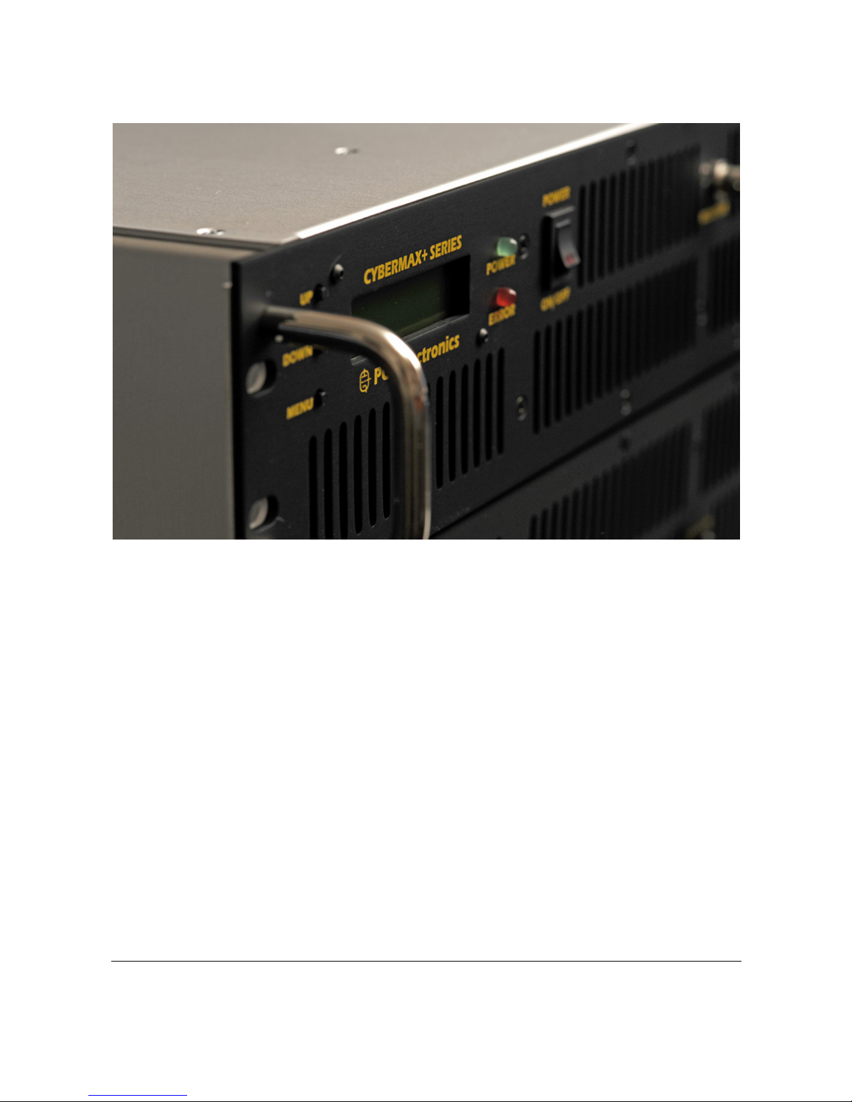
Appendix B – Front and back panel layout
Fig. 22: Front panel
Reference Function
1 Three push buttons, the UP, DOWN and MENU keys.
2 LCD display that lets you control the unit and monitor various parameters.
3 The green and red led. Green signals power and red signals error.
4 Power switch in the middle of the panel is actually a standby switch. To really
disconnect the unit from mains power use the main switch at the back.
5 Monitor output on the right can be used to connect various measuring
instruments, such as frequency meter, spectrum analyzer etc. It provides a
sample of output signal which has been greatly attenuated and does not
represent any danger to measuring equipment.
6 Input ventilation slots for RF section
A,A,A,A Install rack handles here with provided screws
Front panel of the CyberMaxFM+ series amplifier is shown above. These units are available in black and silver finish. On the far left you see three push
buttons, the UP, DOWN and MENU keys. Next to it is the LCD display that lets you control the unit and monitor various parameters. The green and red
led are right next to the LCD display. Green signals power and red signals error. Power switch in the middle of the panel is actually standby switch. To really
disconnect the unit from mains power use the main switch at the back (shown on the next page). Monitor output on the right can be used to connect various
measuring instruments, such as frequency meter, spectrum analyzer etc. It provides a sample of output signal which has been greatly attenuated and does not
represent any danger to measuring equipment.
Appendix
B
Page 16

Brought to you by PCS Electronics, www.pcs-electronics.com
Fig. 23: Back panel
Reference Function
1 Output connector, going to antenna
2,3,4 Output ventilation apertures for RF section
5 Input connector, going to exciter (only used in amplifiers)
6 MPX input, only used for exciters
7 Output ventilation aperture for mains power supply
8 Mains switch with fuse and mains plug socket
9,10 USB/RS232 remote control, not used at the moment
Back panel of the CyberMaxFM+ series amplifier is shown above.
Page 17

Brought to you by PCS Electronics, www.pcs-electronics.com
Appendix C – Internal layout
Fig. 24: Internal view of the 500/700W amplifier
Internal view of the CyberMaxFM+ series amplifier is shown above. You can see that there are two main sections, mains power supply and control
electronics are on the left. RF section is on the right. You can see there are many fans cooling the RF section and one smaller fan cooling the left section with
electronics. You can also recognize LCD display at the front, RF low pass filter and pallet FM amplifier in the right compartment and nicely routed internal
wiring.
Appendix
C
Page 18

Brought to you by PCS Electronics, www.pcs-electronics.com
Appendix D – Warranty and legal info
Important notice!
Please remember to turn off the transmitter/amplifier when not in use! This goes especially for high powered transmitters. Remember that anything
you broadcast through the transmitter can be heard by anyone tuning in to that frequency. Although it is unlikely certain weather conditions may allow the
signal to go further than your immediate listening area so please don't broadcast anything you don't mind anyone else hearing.
Warranty and servicing!
Within one (1) year of receiving your order, if any product proves to be defective; please contact us via e-mail or our feedback form. Please DO NOT ship
the product back to us without contacting us first and receiving return instructions. After we receive the defective merchandise, we will test it if need be, and
we will ship back to you a non-defective replacement product. Please note that this doesn't cover final RF transistor as it can be damaged by using defective or
poorly matched antenna. An exception is as well any mishandling or abuse by the customer. If the product is defective, you will receive a replacement. If you
choose to return the defective item, rather than replace it, we will charge a 20% restocking fee and your original shipping and handling charges will not be
refunded. The return of the product is at your expense. We believe that this is a fair policy because lower overhead results in lower prices for all of our
customers.
Legal info
It may be illegal to operate this device in your county. Please consult local authorities before using our products! PCS Elektronik d.o.o. is not responsible for
any damage to your PC arising from use of this product and will not be held responsible for any violation of local laws pertaining to the use of this product. It
is entirely your responsibility that you make sure you operate in accordance with local laws and/or regulations.
Limitation of liability
To the law, in no event shall PCS Elektronik d.o.o. or its suppliers be liable for any special, incidental, indirect, or consequential damages whatsoever
(including, without limitation, damages for loss of business profits, business interruption, loss of business information, or any other pecuniary loss) arising out
of the use of or inability to use the PRODUCT, even if PCS Elektronik d.o.o. has been advised of the possibility of such damages. In any case, PCS
Elektronik d.o.o.´s entire liability under any provision of this agreement shall be limited to the greater of the amount actually paid by you for the PRODUCT
or U.S. $5.00; because some states and jurisdictions do not allow the exclusion or limitation of liability, the above limitation may not apply to you.
Also available from www.pcs-electronics.com
We also carry a big range of:
- FM transmitters in assembled and KIT form
- TV transmitters in assembled and KIT form, VHF and UHF
- AM transmitters with extremely clear modulation (PWM design)
- Various accessories for professional and hobby FM radio stations
- A large assortment of hard to obtain RF components (RF transistors; MRF, 2SC, coils, silver plated wire, coaxial cable, capacitors, quartz crystals and many
others)
- PC based FM transmitters (PCI MAX pc based FM transmitter turns your PC into a radio station)
- A large number of beginners guides to get you started
- A large selection of free schematics is as well available at our website.
If you can’t get much range with your homebrew antenna, have a look at these:
http://www.pcs-electronics.com
Appendix
D
Page 19

Brought to you by PCS Electronics, www.pcs-electronics.com
Page 20

Brought to you by PCS Electronics, www.pcs-electronics.com
Revisions and errata
V20 (Dec 2009): Release version of new manual format
Please report any errors you see in this manual, you will be helping us and many other users out there. Thank you!
Page 21

21
Index
AC mains power, 6
adjusting, 7
Antenna, 7
beam, 7
Coaxial cable, 8
directional antenna, 7
feedback, 7
final transistor, 7
FM transmitter, 8
gain, 7
General features:, 5
grounding, 7
H-500, 8
metal case, 7
omni-directional antenna, 7
perfect match, 8
radiation pattern, 7
RF shielded, 7
RG-58, 8
short circuit, 7
SWR, 7, 8
Technical specifications, 6
tune, 7
 Loading...