

Page 1
System 24/48
Installation Manual
Digital Communications
for the Growing Business
Page 2

Copyright (C) PCS digital™
2/2005
Page 3

Table of Contents
Notices .................................................................................................... vii
Disclaimer .............................................................................................. vii
Electric-Static Discharge ........................................................................ vii
Voltage Do’s and Don’t’s........................................................................ vii
Safety Guidelines................................................................................... viii
Life Support Notice ................................................................................ viii
FCC Regulation ..................................................................................... ix
Regulatory Information (U.S.A.)............................................................. ix
FCC Part 68 Compliance ....................................................................... ix
Telephone Company Notification ........................................................... x
Incidence of Injury.................................................................................. x
Hearing Aid Compatibility ....................................................................... x
Year 2000 Compliance........................................................................... x
UL/CSA Safety Compliance ................................................................... x
Notice of Compliance............................................................................. x
Toll Fraud and DISA Disclaimer ............................................................. x
Warranty Repair..................................................................................... xi
Limited Warranty.................................................................................... xi
Exclusions.............................................................................................. xi
i
Installation ................................................................................................... 1-3
Introduction ............................................................................................ 1-3
Welcome to PCS Digital ................................................................... 1-3
System Capabilities .......................................................................... 1-4
About This Manual............................................................................ 1-5
General Description.......................................................................... 1-5
System Components ........................................................................ 1-5
Installation Guide ................................................................................... 1-7
System 24 Wiring and Start-up......................................................... 1-8
System 48 Wiring and St art-up......................................................... 1-10
Single Line Adapter (SLA) Wiring........................................................... 1-12
Specifications......................................................................................... 1-13
Caller ID Installation............................................................................... 1-14
Caller ID Wiring...................................................................................... 1-15
31-Button Display Telephone ................................................................. 1-17
Programming
About this section................................................................................... 2-3
Database Admin Programming the PCS digital System 24/48............... 2-4
Station Database Admin......................................................................... 2-5
Day Class ......................................................................................... 2-6
CO Receive Assignment................................................................... 2-7
Account Code ................................................................................... 2-8
Station DSS Owner........................................................................... 2-9
CO Line Programming ........................................................................... 2-10
CO Line Group ................................................................................. 2-11
Page 4

ii
Table of Contents
Call Handling.......................................................................................... 2-12
Pause ............................................................................................... 2-13
VM Dialing Ratio............................................................................... 2-14
DISA ................................................................................................. 2-15
External Call Forward ....................................................................... 2-16
Call Abandon Time ........................................................................... 2-17
CO Preset Call Forward ................................................................... 2-18
Wait -ICLID....................................................................................... 2-20
Resource................................................................................................ 2-21
Letter Type........................................................................................ 2-22
Database Password ......................................................................... 2-23
Pre-Programmed Messages............................................................. 2-24
System Speed No............................................................................. 2-25
System Time..................................................................................... 2-26
Name Directory................................................................................. 2-27
Data Link .......................................................................................... 2-28
Restriction.............................................................................................. 2-29
Toll Restriction Theory ...................................................................... 2-30
System Application................................................................................. 2-31
Hunt Groups ..................................................................................... 2-32
Voice Mail ......................................................................................... 2-33
Appendix A (Programming PCS digital System 24/48 with PCS Mail) ... 2-34
Feature Code - Alphabetical.................................................................. 2-37
Feature Code - Code ............................................................................. 2-38
System Features and Operation ................................................................. 3-1
General Conventions ............................................................................. 3-3
Quick Reference Chart .......................................................................... 3-5
Features................................................................................................. 3-11
Account Code ................................................................................... 3-11
Forced and Verified..................................................................... 3-11
Unforced and Unverified.............................................................. 3-12
Alarm - Station.................................................................................. 3-12
Alarm - System ................................................................................. 3-13
Alternate Attendant Position ............................................................. 3-14
Answering Machine Emulation ......................................................... 3-14
Attendant Administration................................................................... 3-15
Service Mode .............................................................................. 3-15
Attendant Position ............................................................................ 3-16
Authority Code - Traveling Class of Service ..................................... 3-16
Auto Line Select ............................................................................... 3-17
Automatic Redial .............................................................................. 3-18
Background Music ............................................................................ 3-18
Busy Lamp Field (BLF)..................................................................... 3-18
Call Back .......................................................................................... 3-19
Call Brokering ................................................................................... 3-20
Call Forward Display ........................................................................ 3-20
Page 5

Table of Contents
iii
Call Forward ..................................................................................... 3-20
No Answer................................................................................... 3-21
Busy ............................................................................................ 3-22
Busy / No Answer........................................................................ 3-22
Idle .............................................................................................. 3-22
All Call ......................................................................................... 3-23
Follow Me.................................................................................... 3-23
Call Park........................................................................................... 3-24
Call Pickup........................................................................................ 3-25
Direct Station............................................................................... 3-25
Group .......................................................................................... 3-25
Call Waiting....................................................................................... 3-26
Caller Identification ........................................................................... 3-26
Caller Identification Review .............................................................. 3-27
Class of Service................................................................................ 3-27
CO Line Access................................................................................ 3-29
CO Line Assignment......................................................................... 3-29
CO Line Group Assignment.............................................................. 3-30
CO Line Pool .................................................................................... 3-30
CO Line Status Indication ................................................................. 3-31
CO Line Type Assignment ................................................................ 3-31
Conference ....................................................................................... 3-32
Supervised .................................................................................. 3-32
Unsupervised .............................................................................. 3-33
Direct Inward System Access (DISA) ............................................... 3-34
Directory Dial .................................................................................... 3-36
Distinctive Ring - CO Line ................................................................ 3-37
Distinctive Ring - Station................................................................... 3-37
Do Not Disturb .................................................................................. 3-38
Do Not Disturb Override ................................................................... 3-38
Drop Caller Time-Out........................................................................ 3-38
DSS Console .................................................................................... 3-39
External Call Forward ....................................................................... 3-40
Flash................................................................................................. 3-40
Flex Button Review and Programming ............................................. 3-41
Forced Tone Ring ............................................................................. 3-44
Headset Mode .................................................................................. 3-44
Hold .................................................................................................. 3-45
System Hold................................................................................ 3-45
Exclusive Hold............................................................................. 3-46
Reminder Time............................................................................ 3-46
Hold Abandon (Loop Supervision)............................................... 3-46
Automatic Hold............................................................................ 3-47
Hot Line ............................................................................................ 3-47
Hour Mode Selection ........................................................................ 3-49
Hunt Groups ..................................................................................... 3-49
Intercom Calling................................................................................ 3-50
Page 6

iv
Table of Contents
Last Number Redial.......................................................................... 3-51
Letter Scheme .................................................................................. 3-51
Loud Bell Control .............................................................................. 3-52
Message Waiting .............................................................................. 3-52
Leave a Message........................................................................ 3-52
Receiving a Message.................................................................. 3-53
Cancellation ................................................................................ 3-53
Music on Hold................................................................................... 3-53
Mute ................................................................................................. 3-53
Muted Ringing .................................................................................. 3-53
Night Service .................................................................................... 3-54
One Button Record........................................................................... 3-54
Paging .............................................................................................. 3-55
Pause ............................................................................................... 3-56
Preset Call Forward.......................................................................... 3-56
Privacy Release................................................................................ 3-57
Private Line....................................................................................... 3-58
Receive Assignment ......................................................................... 3-58
Ring Assignment............................................................................... 3-59
Ringing Line Priority ......................................................................... 3-59
Save Dialed Number ........................................................................ 3-60
Station Camp On .............................................................................. 3-60
Station Feature Status Check ........................................................... 3-61
Station Groups.................................................................................. 3-61
Station Lock / Unlock........................................................................ 3-62
Station Message Detail Recording (SMDR)...................................... 3-63
Station Speed Dial ............................................................................ 3-63
Saving Speed Dial Numbers ....................................................... 3-64
Retrieving Speed Dial Number.................................................... 3-64
System Speed Dial ........................................................................... 3-65
System Time..................................................................................... 3-65
Text Messaging................................................................................. 3-66
Sending a Text Message ............................................................. 3-66
Receiving a Text Message .......................................................... 3-67
Station Notification ...................................................................... 3-67
Toll Restriction .................................................................................. 3-68
Tone / Inter-digit Duration ................................................................. 3-69
Tone / Pulse Mode............................................................................ 3-69
Pulse-to-Tone Switch over........................................................... 3-69
Transfer ............................................................................................ 3-69
Supervised .................................................................................. 3-69
Unsupervised .............................................................................. 3-70
Transfer Recall ................................................................................. 3-70
Trunk Queuing.................................................................................. 3-71
User Names...................................................................................... 3-72
User Saved Number Redial.............................................................. 3-73
Voice Announce................................................................................ 3-73
Page 7

Voice Mail Button.............................................................................. 3-74
Voice Over Busy ............................................................................... 3-74
Activating..................................................................................... 3-74
Rejecting ..................................................................................... 3-74
Talk Back..................................................................................... 3-74
V olume Control................................................................................. 3-75
Warning Tone.................................................................................... 3-75
Appendix A - Customer Database Worksheets............................................ A-1
Station Flexible button Worksheet......................................................... A-2
Station Programming Worksheet ........................................................... A-3
CO Line Programming Worksheet ......................................................... A-5
Call Handling Programming Worksheet ................................................. A-7
Resource Programming Worksheet ....................................................... A-9
Toll Restriction Programming Worksheet ............................................... A-11
Single Line St ation Number Conversion ................................................ A-3
System Application Programming Worksheet ........................................ A-13
v
Appendix B - Index ...................................................................................... B-1
©Copyright PCS digital
TM
All rights reserved - 02/2005
Page 8

vi
Page 9

Notices
vii
Notices
Disclaimer
This manual contains current information about the PCS digital™ as
written during the month of April 2003, the contents are subject to
change without notice. Every effort has been made to ensure the
accuracy of any information provided.
Electric-Static Discharge
All electronic boards are susceptible to electro-static discharge and
the PCS digital™ is no exception. Care should be taken in when
handling the circuit by the edges only and keeping the cards in antistatic
bags is imperative. Us an antistatic wrist strap or grounding strap
while installing the equipment. Any damage cause by electro-static
discharge or mishandling will void the warranty provided by PCS
digital™.
Voltage Do’s and Don’ts
Ensure to check your local electrical codes for proper installation of
telephone and electronic components. Follow the safety guidelines
provided by the UL document 1459, issue 2, which is the safety
specification for telephone equipment installation. Check your outlet
for proper wiring and voltage levels, your neutral to ground voltage is
critical for electronic equipment optimal operation and longevity.
Typically an AC voltage reading of less than .5 VAC between your
neutral to ground is required.
Safety Guidelines
When installing telephone equipment, the basic safety precautions
should be met in order to minimize the risk of fire and or electrical
shock.
◊ Read and understand all instructions in this manual and safety
documentation.
◊ Do not use or install equipment where it is prone to water hazard
or leakage.
◊ Read and understand all labels on product prior to installation.
◊ Equipment is manufactured with ventilation holes since they contain
no fan; proper care must be taken so that these vents do not get
blocked. There is a risk of equipment failure or fire if these vents
are blocked.
◊ Install equipment on a dry flat fire retardant Plywood and never
install on a shelf or desktop.
Page 10

viii
Notices
Life Support Notice
Since this product is not sold with a built in battery backup or UPS
(Un-interruptible Power Supply), it is not the intent that this unit be
installed in a life support environment or elevator.
FCC Regulation
This equipment has been tested by an independent lab and found to
comply with the limits for a Class A digital device, pursuant to part 15
of the FCC Rules as reproduced below.
These limits are designed to provide reasonable protection against
harmful interference when the equipment is operated in a commercial
environment. The equipment generates, uses and can radiate radio
frequency energy and, if not installed and used in accordance with
the instruction manual, may cause harmful interference to radio
communications. Operation of this equipment in a residential area is
likely to cause harmful interference in which case the user will be
required to correct the interference at his own expense. FCC ruling
states that the owner of the system to be installed gives the local
telephone company sufficient advance notice of the intention to use
privately owned telephone equipment. The owner must also furnish
information as to the identification of the particular lines to be connected
to the system and the affected telephone numbers. FCC registration
information on the model number, FCC-assigned registration number
and ringer equivalence information must also be furnished. The ringer
equivalence (REN) is used to determine how many devices can be
connected to a telephone line. In most areas, the sum of RENs of all
devices on one line should not exceed five. If too many devices are
attached, they may not ring properly. Should there be any questions
that the customer provided equipment causes harm to the telephone
network, the local operation company is required to notify the customer
of an impending temporary interruption of service. The customer must
be given the opportunity to correct the existing problem, if possible.
The telephone company must also advise customers of their rights
for filing complaints before the FCC. The telephone company may
make changes in its technical operations and procedures. If such
changes affect the compatibility or use of the system, the telephone
company is required to give adequate notice of the changes. Under
no circumstances is the equipment to be altered or modified without
written approval of the manufacturer. Failure to gain permission for
any modification will void the warranty.
Page 11
Notices
“This equipment generates and uses RF energy and if not installed and used in
accordance with the Instruction Manual, may cause interference to Radio Communications.
It has been tested and found to comply with the limits for a Class A computing device,
pursuant to Subpart J of Part 15 of the FCC Rules, which are designed to provide
reasonable protection against such interference, when operated in a commercial
environment. Operation of this equipment in a residential area is likely to cause interference,
in which case the user, at his own expense, will be required to take whatever measures
may be required to correct the interference.”
ix
Regulatory Information (U.S.A.)
The Federal Communications Commission (FCC) has established
rules that allow the direct connection of the PCS digital™ System 24
and PCS digital™ System 48 systems to the telephone network.
Certain actions must be undertaken or understood before the
connection of customer provided equipment is completed.
FCC Registration Number for PBX or
hybrid operation (CO Line accessed
by means of dial-access-codes or
FCC Registration Number for Key
System operation (CO Line access by
Ringer Equivalence Number (REN) or 1.0B 1.2B
Type and USOC number of the inter RJ21X RJ21X
D6XTAI-23086-MF-E D6XTAI-25245-MF-E
Telephone Company Notification
Before connecting the PCS digital™ System 24 and PCS digital™
System 48 system to the telephone network, the local telephone
company must be given advance notice of intention to use customerprovided equipment, and must be provided with the following
information:
◊ Telephone numbers to be connected to the system
◊ PCS digital™ System 24 or System 48 system information
◊ Ringer Equivalency Number (REN)
◊ USOC jack required for direct interconnection with the telephone
network (RJ11C)
◊ FCC Registration Numbers (Refer to Table A)
D6TAI-25246-KF-E
Page 12

x
Notices
Incidence of Injury
The telephone company determines that the customer-provided
equipment is faulty and possibly causing harm or interruption to the
telephone network, it should be disconnected until repairs can be
made. If this is not done, the telephone company may temporarily
disconnect service.
Hearing Aid Compatibility
All PCS digital™ Systems’ digital terminals are Hearing Aid Compatible,
as defined in Section 68.316 of Part 68 FCC Rules and Regulations.
UL/CSA Safety Compliance
The PCS digital™ System 24 and 48 have met all safety requirements
and were found in compliance with the Underwriters Laboratories (UL)
1459.
Notice of Compliance
The PCS digital™ System 24 and 48 comply with all rules regarding
radiation and radio frequency emissions by Class A computing devices.
In accordance with FCC Standard 15 (Subpart J), the following
information must be supplied to the end user:
Toll Fraud and DISA Disclaimer
The PCS digital™ System 24 / 48 device is designed by PCS digital™
to be reasonably secure against intrusions from fraudulent callers, it
is by no means fraud proof. Therefore, no express or implied warranty
is made against such fraud including interconnection to the long
distance network
While this device is designed to be reasonably secure against invasion
of privacy , it is by no means invulnerable to such invasions. Therefore,
no express or implied warranty is made against unlawful or
unauthorized utilization which results in the invasion of one’s right of
privacy.
PCS digital™ has made reasonable effort to ensure that this product
works in most business environments. There may be some
environments (RFI and EFI) in which this product may not work. In
such cases, it is the responsibility of the interconnect to take the
necessary actions to correct any RFI interference.
Page 13
Use of Station Lock Feature 97 will restrict access to 911. Also, use of
certain music sources for BGM or MOH may violate copyright laws.
Notices
xi
Warranty Repair
If you have troubles the with the PCS digital™ System 24 or the PCS
digital™ System 48, please contact PCS digital™ technical support
at (480)-222-1159 for repair, return authorization or warranty
information.
Limited Warranty
PCS digital™ provides original purchases with a limited warranty
against defects in material and workmanship on this product for three
(3) years from date of purchase. This limited warranty is extended
only to original purchasers.
THIS WARRANTY SPECIFICALLY EXCLUDES THE IMPLIED
WARRANTIES OF MERCHANTABILITY AND FITNESS FOR ANY
PARTICULAR PURPOSE. THIS LIMITED WARRANTY IS IN LIEU
OF AND EXCLUDES ANY CLAIMS BY THE PURCHASER FOR
CONSEQUENTIAL OR INCIDENTAL DAMAGES.
Exclusions
This warranty does not apply to defects or malfunctions caused by
abuse, accident, modification, negligence or any other damage not
resulting from defects in the original materials or workmanship or for
reasons beyond the control of PCS digital™.
Some states do not allow for the exclusion of consequential or
incidental damages. In which case the foregoing exclusions may not
apply to you. This warranty gives you specific legal rights that vary
from state to state.
Page 14

xii
Notices
Page 15

PCS digital
System 24
and
System 48
1-1Installation
TM
Installation
Page 16

1-2
Installation
Page 17

Introduction
This manual is intended to provide the information necessary to install, program and
maintain the PCS digital™ System 24 and System 48.
Welcome to PCS digital™
The PCS digital™ is a compact, digital communication system. PCS digital™ has been
designed to provide today’s business with a feature-rich system enabling even the
smallest company to project the image of a much larger company. Overall productivity
of the company will increase because applications may be solved based on a compliment
of communication features.
System Capabilities
The PCS digital™ provides a single company with the following two important business
services:
1-3Installation
Attendant Functions
PCS digital™ provides:
◊ Dial an extension number to reach someone.
◊ One button transfer with DSS appearance.
◊ Key or PBX line access.
◊ Hot Pad dialing.
Direct CO Line Ringing
◊ Day and Night Ring schedule.
◊ Ring multiple extensions.
◊ Ring to Hunt groups.
◊ External Preset transfer off site.
Page 18
1-4
About this manual
About this manual
Installation
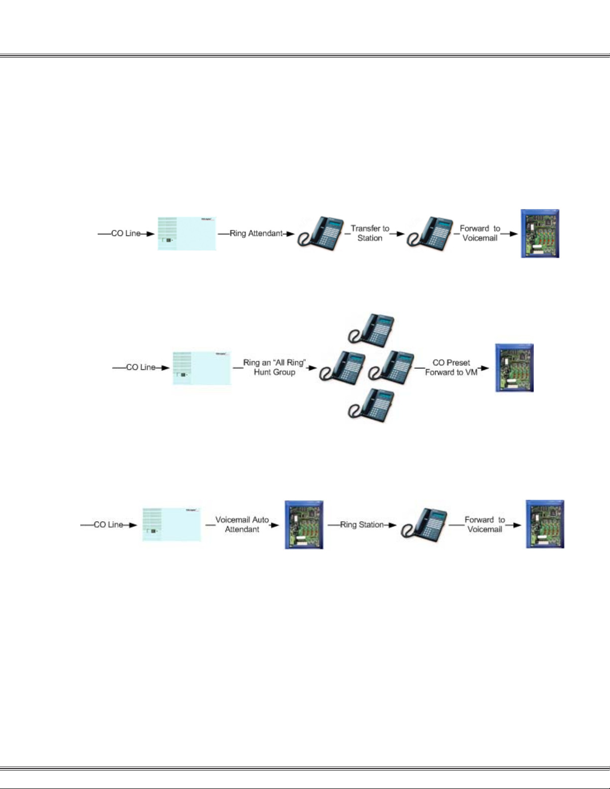
This manual is intended to establish a guideline for the most common types of PCS
digital™ System 24 and System 48 installations.
Typically there are two type of customer scenario’s;
A) The customer that insists that calls be answered by a human first, then transferred
to the appropriate party or station.
System 24 / 48
PCS Mail
An alternative to ringing one station, ring an “All Ring Hunt Group”
System 24 / 48
All Ring Hunt Group
PCS Mail
B) The customer that has realized the value in having an auto attendant answer the
calls and transfer to the appropriate party or extension.
System 24 / 48
PCS Mail Answers
the call
Dialed Station
PCS Mail
Page 19

PCS digital™ General Description
The PCS digital™ System 24 and System 48 system technology incorporates a digital
technology for voice switching and call processing utilizing Pulse Code Modulation and
Time Division Multiplexing (PCM/TDM). The PCS digit al™ System 24 and System 48
are allowed to migrate the digital terminals and terminal accessories throughout the
entire PCS digital™ Systems. ISDN-like, 2B+D technology complements the system
architecture and capabilities. On one industry standard twisted pair, key telephones
perform all system functions and voice communications. Some additional features of
the PCS digital™ systems include:
◊ A non-blocking switch, with no loss or degradation of voice signals.
◊ Stored-Program Control (SPC), utilizing a 16-bit, 8 MHz microprocessor.
◊ Memory consists of 512 KB of Read Only Memory (ROM) and 128 KB of Random
Access Memory (RAM).
When an analog device interface is required, a 2-Port Central Office (CO) Module may
be connected to any one digital station port. The 2B+D technology allows the PCS
digital™ systems to split one digital key telephone port voice channel (B1) and the
second voice channel (B2) to provide two independent SL T -type device interfaces. The
2-Port CO Module may be expanded with the 2-Port Analog Expansion (in the 2-Port
CO Module housing).
1-5Installation
Installation Guide
The 2-Port CO Module and 2-Port Analog Expansion each require one dedicated digital
station port.
System Components
The PCS digital™ system 24 and system 48 systems are comprised of two key telephone
models, an optional Direct Station Selector (DSS) and a modular Key Service Unit
(KSU) which houses the following KSU components:
◊ 3 x 8 Module
◊ Option Module
The application of analog devices in the PCS digital™ System 24 and System 48 has
the effect of two-to-one port gain. For every single digital port used to interface with the
2-Port Single Line Adaptor Box or Expansion card, two analog ports are available.
Page 20

PCS digital™ System 24 / 48 Installation Guide
Guidelines
1. Remove all equipment from boxes and inspect for damage. If damage or abuse is
detected, please contact the PCS digital™ MRA department at:
(480)-222-1159.
2. Locate the wall mounting template and screws. Note: In some situations the
installation might require different or longer screws. Place template level on wall
and fasten screws where indicated on template for mount holes. Remove template
from wall.
3. Remove the four (4) screws which secure the cover to the PCS digital KSU.
4. Locate the screw holes in both upper corners of the KSU. Holding the KSU with the
letters upright will provide that your unit is properly positioned.
1-7Installation
Installation Guide
5. Hang KSU on wall, using the screws that you fastened onto the template.
6. Plug the amphenol cable onto the 3 X 8 Card / Board and punch down station wiring
according to the wiring plan provided in this manual.
7. Plug the power cord into a 1 17
+ 10% V AC outlet. It is a good idea to double check
the viability of the outlet ground by testing between the neutral and ground lugs,
which ideally has an AC voltage reading of less than .5 VAC.
8. Apply power to the KSU by pressing the KSU switch to the ON position. KSU has a
solid Red LED.
9. Now toggle the S-1 initialization switch into the ON position, KSU Red LED is now
flashing.
10. If your wiring is correct then you should have station 10 displaying on your first
station.
11. System needs to be left plugged in for 12 continuous hours to ensure database
back up battery will maintain any Admin Database changes.
Page 21
1-8
System24 Wiring and Start-up
System 24 Wiring and Start-up
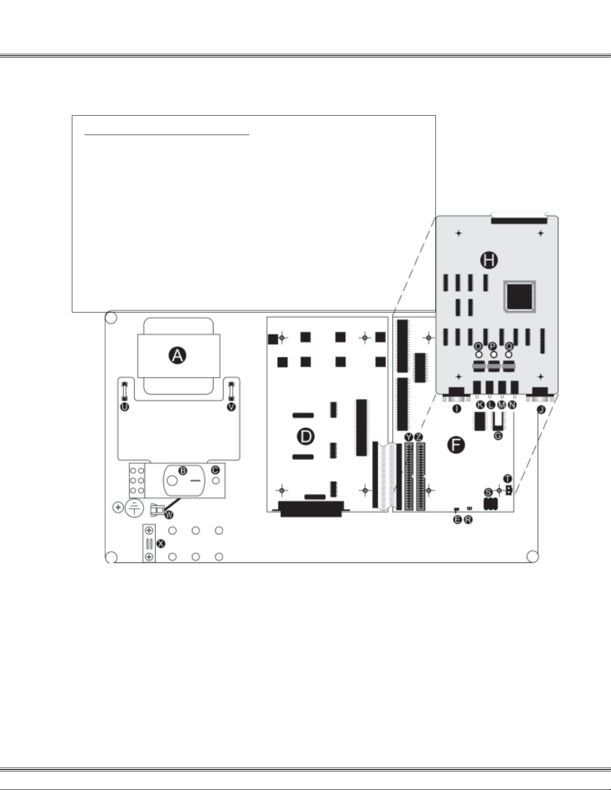
PCS digital™ System 24 Start-up Procedure
Installation
Step 1: Before plugging the KSU in, check all connections:
Step 2: Turn Initialization Switch E ON (right).
Step 3: Plug the system into a UPS or Surge Suppressor. Never plug the KSU directly into a
Step 4: Turn the power switch B ON (right position marked with -) and observe the LED C.
Note: If the LED does not flash within 10 seconds, turn the power switch B OFF, turn the
Initialization Switch
1. Turn the power switch B off (left position marked with an O).
2. Main power connector T to Main Board.
3. Battery charge connector R to Main Board.
4. 3x8 Ribbon Cable to Main Board.
5. Option Module Ribbon Cable to Main Board.
6. 25-pair Champ connector to 3x8 Board.
7. Ground the cabinet.
8. Make sure the Initialization Switch E is turned OFF (left) for 2 minutes.
wall outlet. A power surge can damage the system, and will void the warranty.
The LED should begin to flash within 10 seconds.
E OFF for at least 2 minutes, and repeat steps 2 thru 4.
A Power Supply
B On / Off Switch
C Diagnostic LED
D 3x8 Board (3 CO x 8 Station)
E Initialization Switch
F CPU Board
G EPROM Software
H Option Board
I SMDR RS-232 Port
J Remote Programming RS-232 Port
K Loud bell Connector (24 vdc,1amp)(1/8” Mono-Phono Plug)
L Background Music (BGM) Connector
(1/8” Mono-Phono Plug)
M External Paging Port Connector (1/8” Mono-Phono Plug)
N Music on Hold (MOH) Connector (1/8” Mono-Phono Plug)
O BGM Volume Control
P Paging Volume Control
Q MOH Volume Control
R Ni-MH Battery Power Supply Connector
S Ni-MH Battery for Memory Backup
T KSU Power Supply Connector
U DC Fuse
V AC Fuse
W Power Loss Backup Connector
X Cable Stay
Y Expansion Slot for 3x8 Board
Z Expansion Slot for 3x8 or 6 CO Board
Page 22
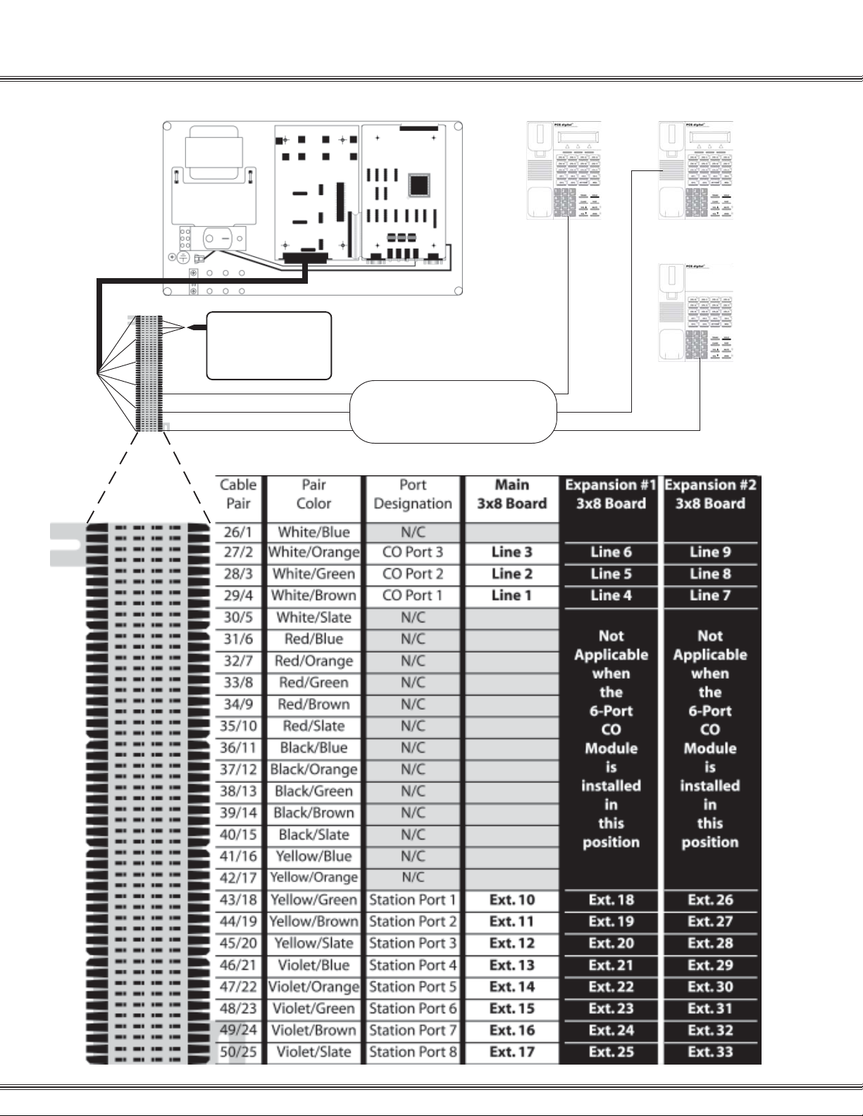
CO / PBX
LINES 1 thru 3
24AWG CAT3
Single Twisted Pair Wire
MDF
1-9Installation
Punch down
Stations 10 thru 17
Page 23
1-10
System48 Wiring and Start-up
System 48 Wiring and Start-up
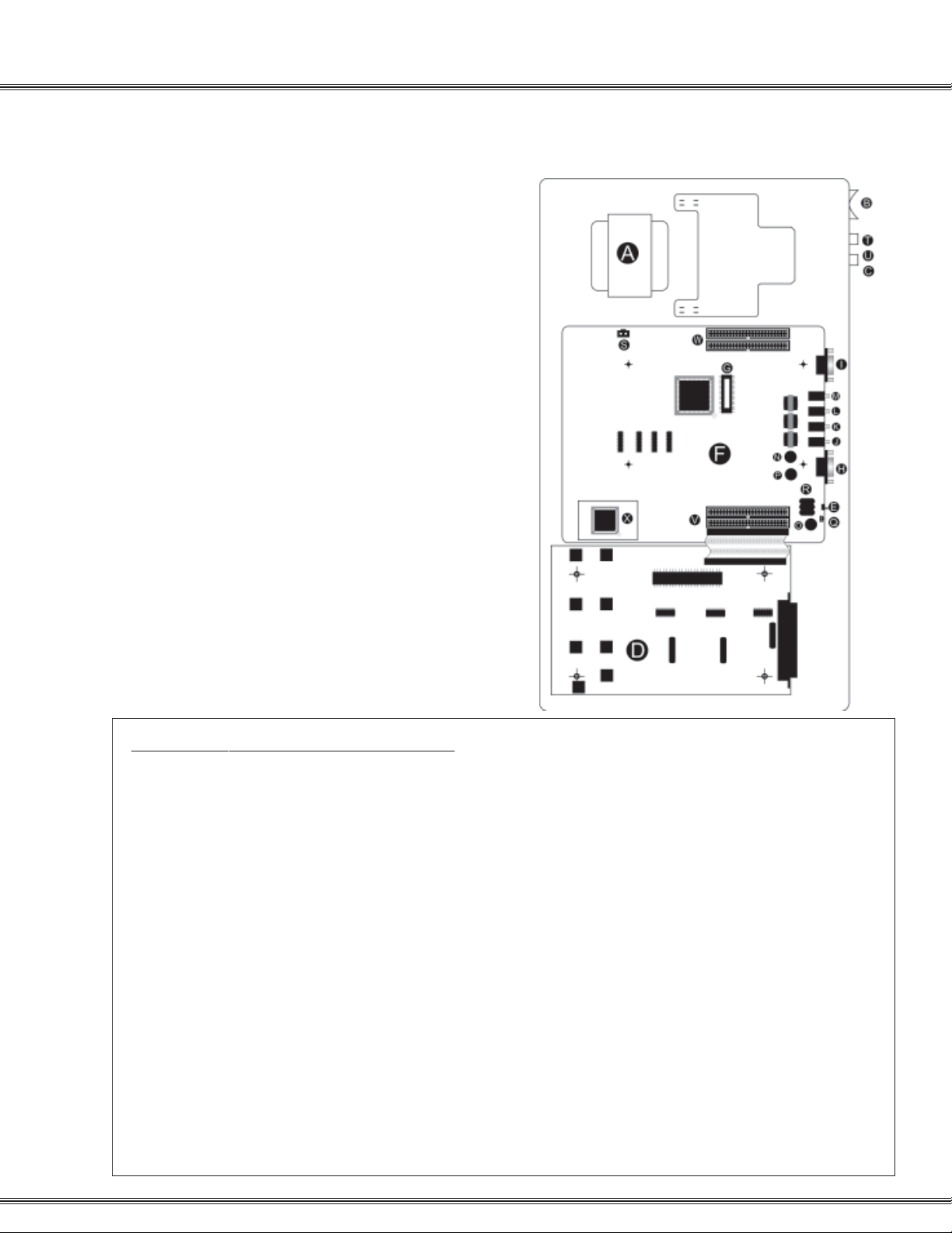
A Power Supply
B On / Off Switch
C Diagnostic LED
D (2) 3x8 Boards (3 CO x 8 Station each)
E Initialization Switch
F CPU Board
G EPROM Software
H SMDR RS-232 Port
I Remote Programming RS-232 Port
J Loud bell Connector
K External Paging Port Connector
L Music on Hold (MOH) Connector
M Background Music (BGM) Connector
N BGM Volume Control
O Paging Volume Control
P MOH Volume Control
Q Ni-MH Battery Power Supply Connector
R Ni-MH Battery for Memory Backup
S KSU Power Supply Connector
T DC Fuse
U AC Fuse
V Expansion Slots for 3x8 Boards 3 and 4
W Expansion Slots for 3x8 Boards and 6
Installation
Note: Connectors “ J K L M” are 1/8 inch mono phono plugs
Note: The Loud Bell Connector “”J” is rated at 24 vdc
1 amp. DO NOT USE AN AC POWER SUPPLY. The use
of AC will result in a loud bell failure.
PCS digital™ System 48 Start-up Procedure
Step 1: Before plugging the KSU in, check all connections:
1. Turn the power switch B off (left position marked with an O)
2. Main power connector to Main Board at S
3. Battery charge connector to Main Board at Q
4. 3x8 Ribbon Cable to Main Board
5. 25-pair Champ connectors to 3x8 Boards
6. Ground the cabinet
7. Make sure the Initialization Switch E is turned OFF (down) for 2 minutes
Step 2: Turn Initialization Switch E ON (right).
Step 3: Plug the system into a UPS or Surge Supersessor. Never plug the KSU directly into a wall outlet. A
power surge can damage the system, and will void the warranty.
Step 4: Turn the power switch B ON (right position marked with -) and observe the LED C. The LED
should begin to flash within 10 seconds.
Note: If the LED does not flash within 10 seconds, turn the power switch B OFF, turn the Initialization
Switch E OFF for at least 2 minutes, and repeat steps 2 thru 4.
Note: The 6-CO board 7100-10 was designed for the System24 and it does not work in the System48
Page 24

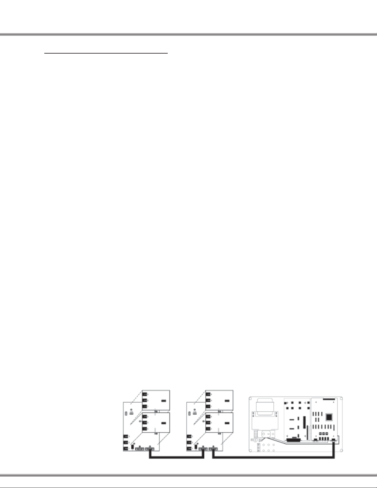
1-11Installation
CO / PBX
LINES 1 thru 6
24AWG CAT3
Single Twisted Pair Wire
Punch down
Stations 100-107
MDF
1-34-6
MDF
Stations 108-115
Secondary
3x8 Board
Page 25

1-12
Single Line Adaptor
Single Line Adaptor (SLA) Wiring
PCS digital™ System 24 / 48
Installation
PCS digital™
SLA
2 1 Out 2 = B2-Station + 48
Digital Extension 10
Analog Extension 58
Out In Out 1= B1-Same Station
Analog Extension 10
System 24 Conversion Chart System 48 Conversion Chart
Digital Station
Station 10
System 24
Analog Extension
Ext. 10 & 58
Digital Station
Station 100
System 48
Analog Extension
Ext. 100 & 148
Station 11
Station 12
...
Station 33
Ext. 11 & 59
Ext. 12 & 60
...
Ext. 33 & 81
Station 101
Station 102
...
Station 138
Ext. 101 & 149
Ext. 102 & 150
...
Ext. 138 & 186
Note: A single extension is used to create two analog ports. When connecting a digital
port to the analog adaptor, use only the center pair, do not use the outer pair. The digital
signal is divided into two analog signals using the 2B + D technology . The Bearer channels
carry the voice transmission while the Data channel directs the transmission to the correct
single line device.
Page 26

PCS digital™ System 24 / 48 Specification Table
1-13Installation
Specification
System Programming Memory
Ports: PCS digital System 24
DSS Console 12 (Note: one for each digital station)
Ports: PCS digital System 48
DSS Console 12 (Note: one for each digital station)
Digital Stations PCS digital System 24
Digital Stations PCS digital System 48
Standard SLT PCS digital System 24
Standard SLT PCS digital System 48
DTMF Receivers:
2-Port CO Module
2-Port Analog Expansion
Option Module
Protection 300 Hours on a fully-charged battery
(internal Ni-MH battery requires 14 continuous powered hours of system operation to become fully
charged.)
CO / PBX / Centrex Lines 12 (Note: 16 stations max.
with this configuration)
CO / PBX / Centrex Lines 18
24 Digital Stations
48 Digital Stations
46 (Note: one digital port must be reserved for digital
station operation. One digital station port is used for
every 2 SLT ports required.)
94 (Note: one digital port must be reserved for digital
station operation. One digital station port is used for
every 2 SLT ports required.)
2 (One for each SLT port)
2 (One for each SLT port)
2 (Shared for advanced call processing system
features; DISA, ECF) Located on the option Module
DTMF Senders Unlimited.
Tone Detectors
Contacts
DISA Circuits
Dimensions and Weights:
System24
System48
Internal Modem Extension and Settings:
System48 (only)
Communications protocol setup -
1 Used for DISA
1 LBC contact is available via the Option Module
Conference Circuits Four-party conference circuits (8
per system).
Although it is not recommended, all CO lines may be
programmed for DISA operation.
Length 18.4 inches, Width 10.9 inches, and Height 4.2
inches.
Weight (3x8) = 8.8 lbs
Length 25.13 inches, Width 15.62 inches, and Height
4.8 inches.
Weight (9x24) = 25.8 lbs
Extension 199
2400 bps
8 bit
1 stop bit
No Parity
XON/XOFF - Flow Control
Page 27
1-14
Caller ID Installation
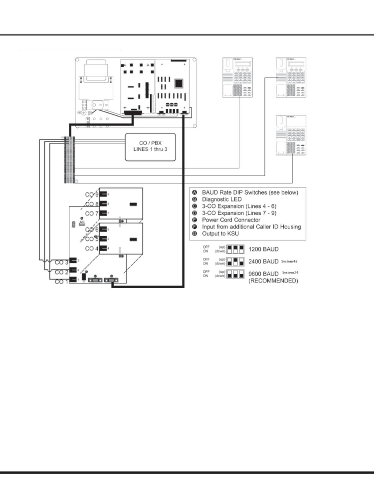
Caller ID (ICLID) Installation
Items Included
Mounting the caller ID unit
Installation
When using caller ID with the System 24 or System48 it is necessary to use the caller
ID unit. The Caller ID unit must be connected to the ICLID/PC programming port on
the option module using the supplied caller ID Cable (9 to 9 pin RS-232C straightthrough cable) to receive caller ID information. PC programming and caller ID collection
cannot be performed simultaneously. See diagram on the next page for wiring
instructions.
The following items are including with the Caller ID unit
◊ Caller ID Unit
◊ 120 VAC to 12 VDC power adapter and cable
◊ 9 to 9 pin RS-232C cable
The Caller ID unit is contained in a wall-mount enclosure with predrilled flanges for
simple mounting. Once mounted the hinged cover will open upward and lock into
position for servicing.
Connecting the Caller ID unit
1. If multiple Caller ID units will be used, connect the Caller ID units together according
to the diagram below.
2. Connect the RS-232C to the output “G” connector (Out) on the Caller ID unit and
connect the other end to the ICLID/PC Programming port.
3. Connect CO line one from the KSU’s MDF to CO line 1 (RJ1 1) on the Caller ID unit.
Repeat this step for all CO lines, connecting them in the order shown on the diagram
on the next page .
4. Plug the power adaptor into a 120 V AC outlet, and insert the remaining end into the
caller ID unit’s DC-In power connector . When power is applied, the red LED in the
Caller ID unit will begin to flash indicating the system is functioning.
Baud Rate Settings:
Confirm the Caller ID unit dip switches (A on next page) are set for 9600 bps for the
System48 and 2400 bps for the System48 Settings range from: 1200 to 9600 bps.
To change the baud rate, make sure you are properly grounded before removing the
CO-3 card located on the top of the unit. The Dip Switches are located in the center of
the board.
Page 28
Caller ID (ICLID) Wiring
1-15Installation
Caller ID Wiring
set up
1. Access Database Programming (f#* + Password).
2. Go to 2. CO Line and press [show].
3. Dial the CO line you wish to program (all CO lines that have Caller ID will need to be
programmed), and then press [show]
4. Go to ICLID PORT #: and press [chg].
5. Dial the port that the CO line is attached to, and press [save]
note: If wired as described on previous page, each port will be the same as the CO Line;
CO Line 1 = ICLID Port 01, CO Line 2 = ICLID Port 02,..., CO Line 9 = ICLID Port 09.
6. To continue Press the h button until the display reads SHOW CO LINE: __
and repeat steps 4 and 5 for all CO Lines with Caller ID attached to the system.
7. Go to 3. Call Handling and press [show]
8. Go to Wait-ICLID:
9. Press [chg] until the display reads: WAIT-ICLID: 7.
10. Go to 4. RESOURCE and press [show]
11. Go to RMT X RATE:
12. Press [chg] until the display reads RMT X RATE:9600 for the System24 and
RMT X RATE:2400 for the System48.
Page 29
31 Button Digital Display Telephone
1-17Installation
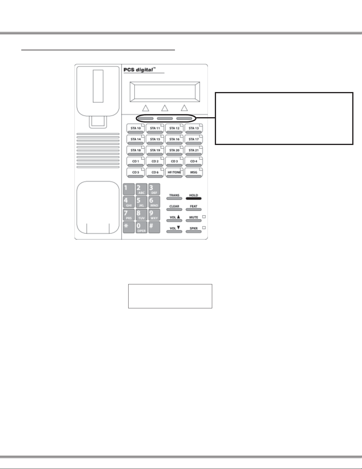
31-Button Digital Display Telephone
For flexibility, the 31 button Display Telephone
uses 3 soft buttons that perform:
* Feature Button Programming
* Attendant Programming
* Database Programming
The Display Telephone has 3 “Soft Buttons” that are located below the display. These
buttons are used for ease of programming. The display will show you the purpose of
each button, depending on the screen you are on. For instance, your display may
read:
STA 10 BUSY
cbck msg next
In this example, the three soft buttons are available as follows:
Left Soft Button: Leave a Call Back message
Center Soft Button: Leave a custom text message
Right Soft Button: Go to the next set of options.
These menu items may be different for each feature of the phone. In general, the
following buttons are used for many features:
back Returns you to the previous menu selection.
bksp Use this to delete the previous character entered, and move back (like the
backspace of a computer)
chg When you are able to enter digits or letters, this will erase the whole string
entered.
next Advance to the next menu selection.
save Saves the current settings
show Displays the settings of the feature displayed.
Page 30

1-18
Installation
Page 31

PCS digital™
System 24
and
System 48
Programming
Page 32

Programming
2-2
Page 33

Programming
2-3
About this section:
This section is designed as a visual guide through the systems’ programming menu screen s from the
31 button display telephone. At the top of each page, you will find the number and name of the
programming section.
SHOW STA: _ _
back show next
On the left side of the page, you will find a graphical reproduction of the
telephone display showing step-by-step what you should see as well as the
default value for each parameter.
If the programming parameter requires you to go into a submenu, the
graphical reproduction shows a smaller version of the display. If you do not
DAY CLASS: 0
back next chg
choose to enter the submenu, press next to go onto the next menu item. If a
submenu has a repetitive list, all parameters are in one continuous screen.
CO LINE 1 : Y
back next chg
CO LINE 2 : Y
back next chg
CO LINE 3 : Y
back next chg
CO LINE 4 : Y
back next chg
CO LINE 5 : Y
back next chg
. . .
CO LINE 18:Y
back next chg
The three soft buttons under the display will assist in the programming
process. If one of the three buttons is labeled “save” the new operation will
become active after the save button is pressed. However, if “save” is not one
of the choices, the moment that the “chg” is pressed, the new value is
displayed and the new operation
becomes active.
On the right side, you will see a brief
description of each programming
parameter as well as any related
programming needed for proper
operation of the current parameter.
SHOW STA: __ __
back show next
Press chg and enter the station number to be
modified. Valid stations are:
System24 – (10 – 48)
System48 – (100 – 148)
Each extension is assigned a day class of service
which is used for DND override, privacy release
and toll restriction. (See 5.Restriction)
Each extension is assigned a night (NITE) class of
service which is used for DND override, privacy
release and toll restriction. (See 5.Restriction)
Page 34

Programming
2-4
Database Admin Programming the PCS digital ™ System 24 / 48
From any digital display extension, press [f] and dial [# *] to enter Admin
Database programming.
[f] # *
DB PSWD:000000
bksp show chg
SYSTEM TYPE: PBX
back next chg
1. STATION
2. CO LINE
3. CALL HANDLING
4. RESOURCE
5. RESTRICTION
6. SYS APPLICATION
back next show
Enter the system password. The default password is 6 zeros (000000). Then Press Save.
Press chg to toggle between KEY and PBX. PBX allows
single line and digital extensions, on the system48, to dial 9
and access a CO Line. When set to KEY each extension
requires a direct appearing CO line.
Press next to scroll through the 6 programming sections
which are used to customize each installation.
The three soft buttons under the display will assist in the
programming process.
Press Hold to back up one programming menu
Press Clear to exit programming
Page 35

Programming
2-5
1. STATION
1. STATION
2. CO LINE
3. CALL HANDLING
4. RESOURCE
5. RESTRICTION
6. SYS APPLICATION
back next show
SHOW STA: _ _
back show chg
DAY CLASS: 0
back next chg
NITE CLASS: 0
back next chg
CO LINE ASSIGNM
back next show
CO LINE 1 : Y
back next chg
CO LINE 2 : Y
back next chg
CO LINE 3 : Y
back next chg
CO LINE 4 : Y
back next chg
CO LINE 5 : Y
back next chg
. . .
CO LINE 18:Y
back next chg
DAY CLASS
NITE CLASS
CO LINE ASSIGNM
RECEIVE ASSIGNM
RING ASSIGNMENT
AC_CODE FORCED
STA GROUP
WARNING TONE
DROP TIMEOUT
STA POSITION
VM PORT
DSS OWNER
Show STA – Press show to customize station
parameters or press next to go to CO Line parameters.
Enter a valid extension number:
System24 – Digital (10 – 25)
System48 – Digital (100 – 147)
Day COS – Each extension is assigned a day and night
(NITE) class of service which is used for DND override,
privacy release and toll restriction. (see 5.Restriction)
Night COS – Press show to view/modify the CO line
assignment for each extension or press next to go to
receive assignment.
CO Line Assignment – This parameter is used to allow
the entered extension access to each of the shown CO
lines. This parameter must be set for every CO line
physically installed in the system. For example, a 3 x 8
system has 3 CO lines, 6 x 16 system has 6 CO lines .
When all questions are answered, you will
automatically go to the next programming parameter,
CO Line Receive Assignment.
Press show to customize
STATION parameters or next to
go to 2. CO LINE
Analog (58 – 73)
Analog (148 – 195)
Press Hold to back up one programming menu
Press Clear to exit programming
Page 36

Programming
Notes:
2-6
Page 37

Programming
1. STATION – Ring Assignment
RECEIVE ASSIGNM
Back next show
CO LINE 1 : Y
back next chg
CO LINE 2 : Y
back next chg
CO LINE 3 : Y
back next chg
CO LINE 4 : Y
back next chg
CO LINE 5 : Y
back next chg
. . .
CO LINE 18:Y
back next chg
2-7
1. STATION
2. CO LINE
3. CALL HANDLING
4. RESOURCE
5. RESTRICTION
6. SYS APPLICATION
back next show
Receive Assignment – Stations with receive
assignment set to Y (Yes) will have the ability to
receive (answer) incoming CO Lines. This
parameter allows the entered extension to receive
access to the shown CO line. This parameter can be
set for every CO line physically equipped in the
system. For example, a 3 x 8 system has 3 CO
lines, 6 x 16 system has 6 CO lines. When all
questions are answered, you will automatically go to
the next programming parameter, CO Line Ring
Assignment.
Press chg to toggle
Values: Y (Yes) N (No)
DAY CLASS
NITE CLASS
CO LINE ASSIGNM
RECEIVE ASSIGNM
RING ASSIGNMENT
AC_CODE FORCED
STA GROUP
WARNING TONE
DROP TIMEOUT
STATION POSITION
VM PORT
DSS OWNER
RING ASSIGNMENT
ack next show
b
CO LINE 1 : BOTH
back next chg
CO LINE 2 : BOTH
back next chg
CO LINE 3 : BOTH
back next chg
CO LINE 4 : BOTH
back next chg
CO LINE 5 : BOTH
back next chg
. . .
CO LINE 18: BOTH
back next chg
Ring Assignment – This parameter establishes
ringing at the entered extension. Each CO line can
be set to ring during the Day, NITE (Night), Both or
None.
This parameter can be set for every CO line
physically equipped in the system. For example, a 3
x 8 system has 3 CO lines, 6 x 16 system has 6 CO
lines.
When all questions are answered, you will
automatically go to the next programming parameter,
Drop Timeout.
Press chg to toggle
Values: DAY, NITE, BOTH, NONE
Press Hold to back up one programming menu
Press Clear to exit programming
Page 38

Programming
1. Station – AC_Code Forced
2-8
AC_CODE FORCED:N
back next chg
STA GROUP: 1
back next chg
WARNING TONE: N
back next chg
DROP TIMEOUT: N
back next chg
STA POSITION: XX
back next chg
VM PORT: N
back next chg
AC_code forced – To force this extension to enter a
valid account code when placing a CO line call,
change this to Y (yes). Once a valid account code is
entered, the extension assumes a new class of
service based on the programming in AC_Code
Table, and can access a CO Line. See AC_CODE
TABLE(2-46)
STA GROUP – Only stations within a common group
will receive zone or group pages as well as the ability
to do a group call pick up. There are 8 groups (1 – 8).
WARNING TONE – When set to Y (Yes), all calls
placed from this extension will receive a warning
tone, which repeats each time the Drop Timeout
Timer expires. (See Call Handling – Warning Time)
DROP TIMEOUT – This parameter is used to limit
the length of time for each outgoing CO line call.
When set to Y (Yes) all calls placed from this
extension will be governed by Warning Time (See
Call Handling). When the timer expires, both parties
will hear a tone and 10 seconds later the call will
automatically be disconnected.
STA POSITION – Determines the extension number
of the entered extension. Once the number is
entered, the extension immediately becomes the new
number. Press chg to modify Values:
System24 – (10 – 25)
System48 – (100 – 195)
VM PORT – To ensure proper operation of a
voicemail system, any stations connected the
voicemail system must be identified as “VM Port Y”.
When set to yes, the system will send these ports
longer DTMF (Dual Tone Multi Frequency) tones.
(See VM Dialing Ratio)
Press Hold to back up one programming menu
Press Clear to exit programming
Page 39

Programming
1. Station – DSS Owner
DSS OWNER: NONE
back next chg
SHOW STA: _ _
back show chg
2-9
1. STATION
2. CO LINE
3. CALL HANDLING
4. RESOURCE
5. RESTRICTION
6. SYS APPLICATION
back next show
DSS owner – Press chg and enter the appropriate
station number (See note below) This parameter
establishes an association between the entered
station and the station where the DSS console is
wired.
Note: Valid station range:
System24 – (10 – 25)
System48 – (100 – 149)
Press “HOLD” to return to “1. Station” to continue
programming.
DAY CLASS
NITE CLASS
CO LINE ASSIGNM
RECEIVE ASSIGNM
RING ASSIGNMENT
AC_CODE FORCED
STA GROUP
WARNING TONE
DROP TIMEOUT
STATION POSITION
VM PORT
DSS OWNER
Station 10
Note:
The DSS Owner is the digital station that, in programming, is associated with a
DSS console. To program a DSS Owner:
1. Go to “SHOW STA” and enter the station number of the DSS
Console.
2. Press next until you get to the “DSS Owner”
3. Enter the digital station (Usually a 31-button display telephone)
that will be associated with the DSS.
For example, with the diagram shown above, you would enter station 11 at the
“SHOW STA”, and the DSS owner is station 10.
Station 11
Press Hold to back up one programming menu
Press Clear to exit programming
Page 40

Programming
2. CO LINE Programming
2-10
1. STATION
2. CO LINE
3. CALL HANDLING
4. RESOURCE
5. RESTRICTION
6.
SYS APPLICATION
back next show
SHOW CO LINE: __
back show chg
DIALING: TONE
back next chg
CALL ABANDON: Y
back next chg
CO LINE TYPE: CO
back next chg
LOUD BELL: Y
back next chg
DIALING
CALL ABANDON
CO LINE TYPE
LOUD BELL
CO LINE GROUP
PRIVATE TO
TOLL OVERRIDE
DISTINCT TONE
ICLID PORT #
Enter the CO Line to be modified. Valid CO Line Range:
System24 – (01 – 09)
System48 – (700 – 717)
Note: The moment the [chg] button is pressed and the value is displayed
that operation becomes active. In other areas of programming where data
is entered from the dial pad, the [save] Soft Button must be pressed.
Dialing tone – The system allows either Touch Tone ® or
Dial Pulse Signaling for older Central Office/PBX
equipment.
Note: This parameter will affect the end to end signaling required for inband signaling used with Voice Mail systems. If a Voice Mail system is
attached, this parameter must be set to “TONE”
Press show to
customize CO LINE
parameters or next to go
to 3. CALL HANDLING
Call Abandon Timer – Enables the CO lines to monitor loop
current supervision.
CO Line Type – The three different CO Line types are CO,
PBX and OPN.
CO: When set to CO (Default), all digits dialed will
be monitored by toll restriction.
PBX: When set to PBX, only the digits dialed after
the PBX dial code is dialed, such as “9” are
monitored by toll restriction.
Open: Any CO line hardware that is installed in the
system, but does not have an active CO line
plugged into it should be set to OPN. For example;
if there are 4 active CO lines in a system, CO lines
5 and 6 should be marked as “OPN” which
eliminates them from being accessed by
specialized features such as Last Number Redial.
Loud Bell – When the extension rings the “loud bell relay”
will close, completing the circuit, which will activate the
ancillary loud bell or strobe light device.
Press Hold to back up one programming menu
Press Clear to exit programming
Page 41

Programming
2. CO Line – Line Group
CO LINE GROUP: 1
back next chg
PRIVATE TO: Y
back next chg
TOLL OVERRIDE: N
back next chg
DISTINCT TONE: 0
back next chg
ICLID PORT #: 0
back next chg
2-11
1. STATION
2. CO LINE
3. CALL HANDLING
4. RESOURCE
5. RESTRICTION
6. SYS APPLICATION
back next show
CO line Groups – are used when programming CO line
access to flexible buttons.
Private To – Is used to establish ringing and exclusive
access at the entered station. Press chg and enter a
valid extension number, Values:
System24 – (10 – 81)
System48 – (100 – 195)
Toll Override – Allows the entered CO line to bypass
and override all toll restriction entries.
Note: Marking this CO line toll override will allow unrestricted dialing.
Distinctive Tone – each CO line can be programmed to
use one of 4 different ring tones. These tones will
override station ring tones.
Incoming Caller ID port – Is required when the system
is receiving Caller ID from the Telephone Company.
Select the port which will be associated with the
external (optional) Caller ID device The default value 0
indicates that no Caller ID will be received on this CO
line and the feature is off. (See Caller ID installation).
Note: The System48 – Always reset this parameter to zero “0” before
entering a two digit (10 – 18) CO Number.
Dialing
Call Abandon
CO Line Type
Loud Bell
Co Line
Group
Private To
Toll Override
Distinct tone
ICLID Port #
Note:
Press Next to program another CO Line or
press Hold until screen displays 2. CO Line
Press Next to go to 3. Call Handling
Press Hold to back up one programming menu
Press Clear to exit programming
Page 42

Programming
3. Call Handling
1. STATION
2. CO LINE
3. CALL HANDLING
4. RESOURCE
5. RESTRICTION
6. SYS APPLICATION
back next show
PRIVACY RLS: N
back next chg
PRIV RLS TONE: Y
back next chg
EX_HOLD TIME: 4
back next chg
FLASH TIME: 0.7
back next chg
REMIND TIME: 30
back next chg
PARK REMIND: 30
back next chg
PRIVACY RLS
PRIV RLS TONE
EX_HOLD TIME
FLASH TIME
REMIND TIME
PARK REMIND
PAUSE TIME
PBX CODE
PBX AUTO PAUSE
DIALING RATIO
VM DIALING RATIO
WARNING TIME
RECALL TIME
SLT HOOK_FLASH
DISA
EXTERNAL FORWARD
UNS CONF TIME
OPERATOR CODE
UNS CONFERENCE
CALL ABANDON TIME
RING ALT POS
CO LN PRESET FWD
WAIT-ICLID
VM MON TIME
2-12
Press show to customize
CALL HANDLING parameters
or next to go to
4. RESOURCE
Privacy Release – When set to Y (Yes), the
Privacy feature is removed from stations with a
lower COS. (see Class of Service / Toll
Restriction)
Privacy Release Tone – When set to Y (Yes), all
parties on an active CO line call will hear a tone
when another party joins in on the conversation.
Note: Disabling this tone may be a violation of State or
Federal Law. Please check with your local law enforcement
agency before disabling this feature.
Exclusive Hold timer will allow calls to remain on
exclusive (private) hold for the duration of this
timer. When the timer expires, the call recalls at
the originating station.
Note: When the timer expires a second time and the CO line
remains on hold the station will receive a second alert tone
and the CO line holding condition will change to System Hold
so that any station may access the holding line.
Flash timer – This is the value needed to activate
Central Office features.
Note: Flash is typically used on CO lines that are equipped
with special features from the Telephone Company such as
3-way calling and Call Waiting. Flash may also be used on
CO Lines connected to a PBX or to Centrex lines for call
transfer on those lines.
Remind Time – A reminder tone will be heard at
the originating station each time this timer
expires.
Note: Setting this parameter to zero (0) will disable the
feature.
Park Remind – is the length of time that a call
can remain in a park location before recalling at
the attendant.
Press Hold to back up one programming menu
Press Clear to exit programming
Page 43

Programming
3. Call Handling – Pause Time
PAUSE TIME: 1
back next chg
PBX CODE: 9
back next chg
PBX AUTO PAUS: 1
back next chg
DIALING RATIO
back next chg
TONE TIME: 70
back next chg
INT_DIG TIME: 70
back next chg
2-13
1. STATION
2. CO LINE
3. CALL HANDLING
4. RESOURCE
5. RESTRICTION
6. SYS APPLICATION
back next show
Pause Time – Is the length of time that must pass
before the next set of digits are dialed and most
commonly used when in Speed dial Bins. The feature
code (f70) is entered, and will produce a “P” in
the dialing string.
PBX code – is the number entered when accessing a
PBX line, the next number dialed will be monitored by
toll restriction. (see Toll Restriction)
PBX Auot Pause – Automatically inserts a pause of
this length after the PBX Code is dialed.
Dialing Ratio – Has two parameters that may be
programmed; Tone Time and INT_DGT Time.
Tone Time: this the actual duration of DTMF
tone that the system will send for each key
pressed while connected to a CO line.
INT_DGT: Time is the minimum actual time
between digits that the system will wait
before sending the next tone.
Note: The PCS digital Sys 24 / 48 TONE TIME and INT_DGT
TIME are set at 70 millisecond and the range is from: 50 to 150
milliseconds.
PRIVACY RLS
PRIV RLS TONE
EX_HOLD TIME
FLASH TIME
REMIND TIME
PARK REMIND
PAUSE TIME
PBX CODE
PBX AUTO PAUSE
DIALING RATIO
VM DIALING RATIO
WARNING TIME
RECALL TIME
SLT HOOK_FLASH
DISA
EXTERNAL FORWARD
UNS CONF TIME
OPERATOR CODE
UNS CONFERENCE
CALL ABANDON TIM
RING ALT POS
CO LN PRESET FWD
WAIT_ICLID
VM MON TIME
Press Hold to back up one programming menu
Press Clear to exit programming
Page 44

Programming
3. Call Handling – VM Dialing Ratio
2-14
VM DIALING RATIO
back next show
TONE TIME: 120
back next chg
INT_DIG TIME: 120
back next chg
WARNING TIME: 3
back next chg
RECALL TIME
back next chg
SLT HOOK_FLASH
back next show
START: 300
back next chg
END: 800
back next chg
Dialing Ratio – Has two parameters that may be
programmed; TONE TIME and INT_DGT TIME.
INT_DGT: the inter-digit time is the minimum
actual time between digits that the system
will wait before sending the next tone.
Tone Time: the tone time is the actual
duration of DTMF tone that the system will
send for each key pressed while connected
to a CO line.
Note: For proper operation of the PCS Mail™ these should remain
at default, 120 milliseconds.
Warning Time – is used in conjunction with the
“Warning Tone” parameter set in the “1. Station”
menu.
Recall Time – is the length of time that a call will
remain on hold before recalling at the station that
placed it on hold.
Note: This setting is system wide for Station Recall.
SLT Hook_Flash – is used to set the minimum and
maximum thresholds for Single Line telephone (SLT)
hook-flash detection for analog ports.
Start – Start is the minimal length of time that
a hook flash must be in order to be
considered valid. Press chg to toggle
through the values: 60 through 1400
milliseconds
END – End is the maximum length of time
that a hook flash can be in order to be
considered valid. Press chg to toggle
through the values: 60 to 1400 milliseconds
Note: The valid SLT HOOK_FLASH range is greater
than 300 milliseconds, but less than 800 milliseconds.
Therefore, a SLT hook flash can vary between these
ranges and still be considered valid.
Press Hold to back up one programming menu
Press Clear to exit programming
Page 45

Programming
3. Call Handling – DISA
DISA
back next chg
ACCESS CODE
back next show
01. EMPTY
back next chg
02. EMPTY
back next chg
. . .
24. EMPTY
Back next chg
CO LINE ATTRIBUT
back next show
SHOW CO LINE:_ _
back show chg
DISA LINE: N
back next chg
DISA DAY COS:0
back next chg
DISA NITE COS:0
back next chg
SERVICE: NEVER
back next chg
TALK TIME: 1
back next chg
2-15
1. STATION
2. CO LINE
3. CALL HANDLING
4. RESOURCE
5. RESTRICTION
6. SYS APPLICATION
back next show
Direct Inward System Access (DISA) –
Access Code – This feature allows an outside caller
to dial in to the system on CO lines marked as DISA.
The caller will hear intercom dial tone, allowing them
to enter their private access code. Once the access
code is verified the system allows the caller to dial an
extension or dial 9 to access an outside CO line and
is able to make an outside call. Each system will
support up to 24 unique DISA access Codes.
Note: The use of this feature could result in unintentional toll
charges. Additionally, it is unwise to mark any CO as toll override
“Y” because it could result in further toll charges.
CO Line Attributes – Are a series of parameters that
can be defined for each DISA CO Line.
Show CO line – Enter the CO line that will have
DISA Access. Valid entries:
System24 – (01 – 09)
System48 – (700 – 717)
DISA Line – Change to Y to indicate that this
CO line should be a DISA type.
DISA DAY COS – This parameter governs
the toll restriction of the entered CO Line,
which is applied to the CO line after a caller
enters their private DISA access code.
DISA NITE COS – Does the same as the
DISA DAY COS when the system is in Night
Mode.
Note: Do not mark a DISA CO line as “Toll Restriction
override!” (See Toll Restriction)
Service – Represents the time of day the
entered CO will be available, day, night
(NITE), always or never.
Talk Time – Determines the length of time a
caller can remain on an active call, once their
DISA Access code is entered. The timer can
be extended by entering the code.
PRIVACY RLS
PRIV RLS TONE
EX_HOLD TIME
FLASH TIME
REMIND TIME
PARK REMIND
PAUSE TIME
PBX CODE
PBX AUTO PAUSE
DIALING RATIO
VM DIALING RATIO
WARNING TIME
RECALL TIME
SLT HOOK_FLASH
DISA
EXTERNAL FORWARD
UNS CONF TIME
OPERATOR CODE
UNS CONFERENCE
CALL ABANDON TIM
RING ALT POS
CO LN PRESET FWD
WAIT_ICLID
VM MON TIME
Press Hold to back up one programming menu
Press Clear to exit programming
Page 46

Programming
3. Call Handling – External Forward
2-16
EXTERNAL FORWARD
back next show
INCOMING: 0
back next chg
OUTGOING: 0
back next chg
SERVICE: NEVER
back next chg
TALK TIME: 1
back next chg
UNS CONF TIME: 1
back next chg
OPERATOR CODE: 0
back next chg
UNS CONFERENCE: Y
back next chg
External forward – requires one inbound and one
outbound CO line, which will be joined by system
speed bin 99 (See System Speed Bin)
Incoming / Outgoing – Select an inbound and an
outbound CO line to be used.
System24 – (01 – 09)
System48 – (700 – 717)
Service – Represents the time of day the entered
CO will be available, day, night (NITE), always or
never.
Talk Time – Determines the length of time a caller
can remain on an active call, once their DISA
Access code is entered. The timer can be
extended by entering the code.
Unsupervised Conference Timer – is the timer that
governs the length of an unsupervised conference.
Operator Code – Press “chg” to toggle between 9
and 0. This establishes the digit used to access
the operator from within the system.
Unsupervised Conference – Allows or denies any
CO line to be part of an unsupervised conference.
An unsupervised conference is where 2 or more
CO lines are conferenced together without an
internal party being present. An unsupervised
conference will follow the unsupervised conference
timer.
Press Hold to back up one programming menu
Press Clear to exit programming
Page 47

Programming
3. Call Handling – Call Abandon Time
CALL ABANDON TIM
back next show
ACTIVE CALL: 600
back next chg
HELD CALL: 600
back next chg
RING ALT POS: 30
back next chg
Call Abandon Time – Has two parameters which
are active call and held call. The call abandon time
represents the minimum interruption in loop current
during these modes of operation that must be
detected to force a CO line on-hook.
Ring Alternate Position – This value represents the
amount of time, in seconds, that will pass before
the alternate ringing position begins to ring. Press
chg to toggle through the values between 30 and
180.
NOTE: One station may be assigned as the alternate attendant
position. CO calls that go unanswered at the attendant will ring
at the Alternate Position following expiration of this timer.
2-17
1. STATION
2. CO LINE
3. CALL HANDLING
4. RESOURCE
5. RESTRICTION
6. SYS APPLICATION
back next show
Active call – Press “chg” and enter the
amount of time, from 50 to 2500 (2.5
seconds) milliseconds, that an open loop
must be active to terminate an active call.
Held Call – Press “chg” and enter the
amount of time, from 50 to 2500 (2.5
seconds) milliseconds, that an open loop
must be active to terminate a call on hold.
PRIVACY RLS
PRIV RLS TONE
EX_HOLD TIME
FLASH TIME
REMIND TIME
PARK REMIND
PAUSE TIME
PBX CODE
PBX AUTO PAUSE
DIALING RATIO
VM DIALING RATIO
WARNING TIME
RECALL TIME
SLT HOOK_FLASH
DISA
EXTERNAL FORWARD
UNS CONF TIME
OPERATOR CODE
UNS CONFERENCE
CALL ABANDON TIM
RING ALT POS
CO LN PRESET FWD
WAIT_ICLID
VM MON TIME
Press Hold to back up one programming menu
Press Clear to exit programming
Page 48

Programming
3. Call Handling – CO Preset Forward
2-18
CO LN PRESET FWD
back next show
CO P-FWD TIME:16
back next chg
CO LN ATTRIBUTE
back next show
SHOW CO LINE: _
bksp show chg
ACCESS CODE
Back next show
CO1 DEST: EMPTY
back next chg
CO1 VM: EMPTY
back next chg
A
B
C
D
E
CO Line Preset Call Forward is similar to the No Answer Forward operation in which a timer,
CO P-FWD TIME can be preset for each CO line selected. When a CO line rings the timer is
activated. When the timer expires the call is forwarded to a preset destination.
Please refer to the “Special Preset Call Forward” section on the next page.
Press Hold to back up one programming menu
Press Clear to exit programming
Page 49

Programming
3. Call Handling – Preset Call Forward
Special Preset Call Forward Table
A. Press Change to toggle Preset forward timer from values: 6, 10,
16, 22, 30, 40
B. Press Show to select which CO line is going to be programmed
with preset call forwarding. Valid entries are:
System24 – (01 – 09)
System48 – (700 – 717)
C. Enter a valid CO line, for example 01, then press Show
D. Enter the destination to be forwarded to; such as another
extension, hunt or Voice Mail group. Valid entries are:
System24
Stations: 10 – 95
Hunt or Voice Mail group 82 – 89
System48
Extensions: 100 – 195 and 199 (system modem)
Hunt or Voice Mail group 800 - 809
E. Press chg to enter the VMID. This ID can be used to direct
callers to a specific location in the Voice Mail, for example, for
multi-tenant applications.
2-19
1. STATION
2. CO LINE
3. CALL HANDLING
4. RESOURCE
5. RESTRICTION
6. SYS APPLICATION
back next show
PRIVACY RLS
PRIV RLS TONE
EX_HOLD TIME
FLASH TIME
REMIND TIME
PARK REMIND
PAUSE TIME
PBX CODE
PBX AUTO PAUSE
DIALING RATIO
VM DIALING RATIO
WARNING TIME
RECALL TIME
SLT HOOK_FLASH
DISA
EXTERNAL FORWARD
UNS CONF TIME
OPERATOR CODE
UNS CONFERENCE
CALL ABANDON TIM
RING ALT POS
CO LN PRESET FWD
WAIT_ICLID
VM MON TIME
Press Hold to back up one programming menu
Press Clear to exit programming
Page 50

Programming
3. Call Handling – Wait_ICLID
2-20
WAIT – ICLID: 6
back next chg
VM MON TIME: 10
back next chg
WAIT – ICLID - The amount of time that the
system will wait for the Caller ID signal from
the Telephone Company. Once this timer
expires, the system presents the Caller ID
and the first audible ring to the programmed
extension(s). Valid entries are 3.5 to 7.
Note: Generally, this setting will range from 4 to 6
seconds.
VM Monitor Time – Is used with Answering
Machine Emulation. After a call rings at an
extension and it is forwarded to voicemail,
this timer begins. Once the timer expires,
the call can no longer be monitored or
retrieved. Valid entries are between 10 and
60.
Press Hold to back up one programming menu
Press Clear to exit programming
Page 51

Programming
w
4. Resource
1. STATION
2. CO LINE
3. CALL HANDLING
4. RESOURCE
5. RESTRICTION
6. SYS APPLICATION
back next sho
2-21
RING SCHEME
LETTER TYPE
ATTENDANT
ALTERNATE
SYSTEM ALARM
NITE START
NITE END
DB PSWD
USER PASSWORD
USER NAMES
PREPROG MESSAGE
SYSTEM SPEED NO
BGM
CO LINE COPY
STATION COPY
FEATURE BTN COPY
SYSTEM TIME
AC_CODE TABLE
NAME DIRECTORY
DATA LINK
RMTX_RATE
SMDRX_RATE
HOUR MODE
DIAL TONE DET
DIAL WAIT TIME
RELAY CTRL
KSU REVISION
Press show to
customize Resource
parameters or next to go
to 5. RESTRICTION
RING SCHEME: 0
back next chg
The PCS digital system may be set to three different ringing schemes. In
ring Schemes 0 and 2, ringing is differentiated by cadence so that a user is
aware of the type of call ringing at his station by the tone cadence. In
Scheme 1, ringing of both intercom calls and CO line calls is the same.
Intercom Ringing
CO Line Ringing
Ring Scheme is used to customize the ring
cadence of the system. Press chg to toggle
through the values 0, 1, and 2.
Note: For proper voicemail operation please set the ring scheme to
either 1 or 2. These settings supply the voicemail 1 second of “Ring
Signal” which is needed to recognize an incoming call.
SCHEME 0 SCHEME 1 SCHEME 2
1s ON,
3s OFF
300ms ON,
400ms OFF,
300ms ON,
4 second OFF
1s ON,
3s OFF
1s ON,
3s OFF
300ms ON,
400ms OFF,
300ms ON,
4 seconds OFF
1s ON,
3s OFF
Press Hold to back up one programming menu
Press Clear to exit programming
Page 52

Programming
4. Resource – Letter Type
2-22
LETTER TYPE: 0
back next chg
ATTENDANT: 10
back next chg
ALTERNATE: EMPTY
back next chg
SYSTEM ALARM
back next show
ALARM 1 : EMPTY
back next chg
ALARM 2 : EMPTY
back next chg
…
ALARM 8 : EMPTY
back next chg
NITE START: 17:00
back next chg
NITE END: 08:00
back next chg
Letter type - Is used to customize the characters for
the Messaging and Name in Display features. This
allows the letters to be adjusted to accommodate
special characters and language requirements.
Attendant – Defines the attendant and the extension
that will ring when someone in the system dials “0”.
Alternate – Defines the extension that will ring when
the attendant is unavailable. Valid stations are:
System24 – (10 – 81)
System48 – (100 – 195)
System Alarm – There are 8 system alarms that can
be set to alert all digital station users on the system.
This is generally used to alert all users of a specific
event such as “Lunch”. Idle station users will hear
one minute of background music (BGM).
Note: only idle stations will hear the alert. Extension set to play
BGM may not be able to differentiate between the alarm and BGM.
Alarm 1 – To set a system alarm, Press “chg”
and enter the designated time for each of the
8 alarms. The alarm will play daily at the
programmed time. Enter the time using a 24hour format, 00:00 to 23:59.
Nite Start – Is used when the system is set to timed
(See Attendant Administration). The system will
automatically change from day to night (NITE) mode.
Press chg and enter time in 24-hour format, 00:00 to
23:59.
Nite end – Is used when the system is set to timed
(See Attendant Administration). The system will
automatically change from night (NITE) to day mode.
Press chg and enter time in 24-hour format, 00:00 to
23:59.
Press Hold to back up one programming menu
Press Clear to exit programming
Page 53

Programming
g
4. Resource – DB Password
DB PSWD: 000000
back next chg
USER PASSWORD
back next show
SHOW STA: _ _
back next chg
STA PSWD: 0000
back next chg
USER NAMES
back next show
SHOW STA: _ _
back next chg
STA 10: EMPTY
back next chg
2-23
1. STATION
2. CO LINE
3. CALL HANDLING
4. RESOURCE
5. RESTRICTION
6. SYS APPLICATION
back next show
DB PSWD – Customize the system database
password. The password must be 6 digits in length
and can be any digit between 000000 and
999999. * and # are not valid digits.
User Password – Allows various stations to have a
unique user password as well as establishing the
“Attendant Administration” password. Once the
Attendant is defined in the Resource (See Resource
– Attendant) the Attendant Administration password
becomes that station user’s password. By default the
Attendant is station 10, and the password is
“0000”. Additionally this feature is used to lock
the station. Once locked, the station CANNOT make
any CO line calls. This includes 911 calls. Stations
that have a need to access 911 must never be
locked. Enter extension number and Press “show” to
view the password. Press “next” to continue or “back”
to view another station’s password.
User Name - Allows each telephone to have the
user’s, or specialized name, in the display. Each
name can have up to seven characters. The “Dial
input screen” below will assist in the programming of
the names.
Dial input screen
Key 1st
Depression
1
2
3
4
5
6
7
8
9
0
A B C
D E F
G H I
J K L
M N O
P R S
T U V
W X Y
Q Z Next
To enter a number, rather than a letter,
*
Press “*” before pressing a number key.
For lower case letters Press the “*” key
after a letter is selected.
Space or when two letter are used back to
#
back. Lloyd for example, would require the
followin
Special Characters
entry “555#5556669993”
2nd
Depression
3rd
Depression
RING SCHEME
LETTER TYPE
ATTENDANT
ALTERNATE
SYSTEM ALARM
NITE START
NITE END
DB PSWD
USER PASSWORD
USER NAMES
PREPROG MESSAGE
SYSTEM SPEED NO
BGM
CO LINE COPY
STATION COPY
FEATURE BTN COPY
SYSTEM TIME
AC_CODE TABLE
NAME DIRECTORY
DATA LINK
RMTX_RATE
SMDRX_RATE
HOUR MODE
DIAL TONE DET
DIAL WAIT TIME
RELAY CTRL
KSU REVISION
Press Hold to back up one programming menu
Press Clear to exit programming
Page 54

Programming
2-24
4.Resource – Preprogrammed Messages
PREPROG MESSAGE
back next show
OUTGOING MESSAGE_
back next show
EXECUTIVE NOTIFY_
back next show
OUT FOR LUNCH
back next chg
BE BACK SOON
back next chg
LEFT FOR THE DAY
back next chg
IN A MEETING
back next chg
OUT OF OFFICE
back next chg
ON VACATION
back next chg
There are two types of Preprogrammed Messages;
Outgoing and Executive Notify. The Outgoing
Message works with Message Waiting and allows a
display telephone to display a text message when
called. Executive Notify is used to send a text
message to a busy display telephone.
CALL OPERATOR
back next chg
CALL HOME
back next chg
CALL SCHOOL
back next chg
VISITORS WAITING
back next chg
URGENT
back next chg
COME SEE ME
back next chg
Press Hold to back up one programming menu
Press Clear to exit programming
Page 55

Programming
4. Resources – System Speed No
SYSTEM SPEED NO
back next show
SPEED NO : _ _
back next chg
BGM : Y
back next chg
Each system has 80 (20-99) System Speed Dial Bins.
Note: Access and use of system speed dial bins are governed by the
extensions’ Class of Service (COS) assignment.
COS (0-5) can access all eighty System Speed Dial Bins
COS 6 can only access speed bins 20-39 and override the stations
toll restriction.
COS 7 cannot use System Speed Dial Bins.
Programmable digits are:
Specialized digits are:
Press chg to toggle Y (Yes) or N (No) to enable
background music.
2-25
1. STATION
2. CO LINE
3. CALL HANDLING
4. RESOURCE
5. RESTRICTION
6. SYS APPLICATION
back next show
Digits (0-9) [*], [#]
Pause [f7 0]
Flash [f3]
Chain together up to 16 System Speed Bins [f1 +
NN]
Note: This is a system wide setting.
RING SCHEME
LETTER TYPE
ATTENDANT
ALTERNATE
SYSTEM ALARM
NITE START
NITE END
DB PSWD
USER PASSWORD
USER NAME
PREPROG MESSAGE
SYSTEM SPEED NO
BGM
CO LINE COPY
STATION COPY
FEATURE BTN COPY
SYSTEM TIME
AC_CODE TABLE
NAME DIRECTORY
DATA LINK
RMTX_RATE
SMDRX_RATE
HOUR MODE
DIAL TONE DET
DIAL WAIT TIME
RELAY CTRL
KSU REVISION
CO LINE COPY
back next show
STATION COPY
back next show
FEATURE BTN COPY
back next show
CO line, station and feature button copy all work the same way. The
first entry “Copy From” is the template to be copied. The “Copy To”
is the CO line, station or feature button format that will emulate the
template.
COPY FROM:
back save chg
COPY FROM:
back save chg
COPY FROM:
back save chg
COPY TO:
back save chg
COPY TO:
back save chg
COPY TO:
back save chg
Press Hold to back up one programming menu
Press Clear to exit programming
Page 56

Programming
4. Resource – System Time
2-26
SYSTEM TIME_
back next show
YEAR : 00
back next chg
MONTH: JAN
back next chg
DAY: 00
back next chg
WEEKDAY: MON
back next chg
HOUR: 00
back next chg
MINUTE: 00
back next chg
AC_CODE TABLE
back next show
LENGTH: 4
back next chg
001. EMPTY
back next chg
002. EMPTY
back next chg
. . .
100. EMPTY
Back next chg
System time is displayed on all digital display
telephones. Use the following parameters to
program the current system time and date. Press chg
to change or select the following parameters.
Year – Enter the year in two digit format (05)
Month – Select the current month
Day – Enter the current day (01 - 31)
Weekday – Select the day of the week
Hour – Enter the hour in 24 hour format (00:00 –
23:59). Examples:
14:00 = 2:00 pm
18:00 = 6:00pm
21:00 = 9:00 pm.
Minute – Enter the current minutes (00 – 59)
Account code tables - Are used to store up to 100
unique account codes. When a station user enters
an account code, the codes are verified against these
entries. If a valid account code is entered, the station
will have the ability to override specific toll restrictions
assigned by their Class of Service.
Length – To increase security the account code
length is adjustable from 4 to 8 digits. If the account
code length is increased, after account codes are
entered, those numbers will have a “0” added for
each numbered increased. For example, if 1234 is a
valid 4 digit account code and the account code
length is changed to 8 digits the code 1234 changes
to 12340000. Conversely, if 12345678 is a valid 8
digit account code and the account code length is
changed to 4 digits, the code 12345678 changes to
1234.
“Table” 001 ~ 100 - Enter one unique account code
in each “Table”. Valid entries can be from 0000 –
99999999 depending on the “Length” value.
Press Hold to back up one programming menu
Press Clear to exit programming
Page 57

Programming
4. Resource – Name Directory
NAME DIRECTORY
back next show
SHOW ENTRY:
back show chg
NAME
back next show
EMPTY
back show chg
DESTINATION
back next show
TYPE : ICM
back next chg
DEST: _ _
back next chg
2-27
1. STATION
2. CO LINE
3. CALL HANDLING
4. RESOURCE
5. RESTRICTION
6. SYS APPLICATION
back next show
Name Directory Associates names with Stations or a
System Speed Dial Bins.
Show entry – Enter the Table/bin number of
the entry to be modified. Valid entries are
001 -968
Name – Use the “Dial input screen” (See
page 2-21) to enter the name that will be
associated with the IMC/Speed dial bin.
(“Home”, for example would require the
following entry: 44 666 # 6 33)
Note: Use the “ ” key to insert a space or to go to the
next character when the same letters, on a button, will
be used back to back.
Destination – Is where the name, that was
just entered, is associated with the ICM or
speed dial bin.
Type – Associate the previously entered
name with either an Intercom Extension
(ICM) or a Speed Dial Bin (SPD).
DEST – Enter the Station (ICM) or the Speed
Dial Bin (SPD) Number that will be
associated with the previously entered name.
RING SCHEME
LETTER TYPE
ATTENDANT
ALTERNATE
SYSTEM ALARM
NITE START
NITE END
DB PSWD
USER PASSWORD
USER NAME
PREPROG MESSAGE
SYSTEM SPEED NO
BGM
CO LINE COPY
STATION COPY
FEATURE BTN COPY
SYSTEM TIME
AC_CODE TABLE
NAME DIRECTORY
DATA LINK
RMTX_RATE
SMDRX_RATE
HOUR MODE
DIAL TONE DET
DIAL WAIT TIME
RELAY CTRL
KSU REVISION
Press Hold to back up one programming menu
Press Clear to exit programming
Page 58

Programming
4. Resource – Data Link
2-28
DATA LINK: MANUAL
back next chg
RMT X_RATE: 9600
back next chg
SMDRX_RATE: 9600
back next chg
HOUR MODE: 24
back next chg
DIAL TONE DET: N
back next chg
DIAL WAIT TIME: 0
back next chg
RELAY CTRL:EMPTY
back next chg
Data link - *** Future Feature ****
RMT X_Rate – Adjusts the baud rate for the remote
programming/ICLID port. It can be adjusted from 110
to 19200 kbps. PCSDigital recommends 9600 bps
for the System24 and 2400 bps for the sytem48.
SMDRX_Rate – Adjusts the baud rate for the SMDR
port. It can be adjusted from 110 to 19200 kbps.
Hour mode – Determines how the time will be
displayed on the digital display telephones. Press
chg to toggle between 12 or 24 hour format.
Dial tone det: - This parameter is used with older
Central Office equipment. It will cause a delay before
out dialing is permitted when accessing a CO line.
Note: It is recommended that this feature only be used in cases
where dialing problems persist.
Dial Wait Time – Is used with older central office
equipment, delaying the DTMF digits from being
dialed directly to their equipment.
Note: This timer will override the dial tone detector. Do not change
this value unless instructed by tech support!
Relay control – Enter the extension that will activate
the loud bell relay when it goes off hook.
Note: This feature uses the Loud Bell contact.
KSU REVISION – Press show to see the KSU
software version number. Looks like this. KSU:
K12UV3.F03
KSU REVISION
back next chg
Press Hold to back up one programming menu
Press Clear to exit programming
Page 59

Programming
Toll Restriction
1. STATION
2. CO LINE
3. CALL HANDLING
4. RESOURCE
5. RESTRICTION
6. SYS APPLICATION
back next show
CO LN CALL DISCR
back next show
2-29
Toll Restriction Description:
There are 100 “digit interval locations” or bins that are
used to define the system’s toll Restriction. Toll
Restriction is based on the “Allow Only principal”, and
each table is comprised of four data fields:
Digits From
Digits To
DCOS = DAY COS ALLOWED
NCOS = NITE COS ALLOWED
DGT INTERVAL:###
bksp show chg
FROM: 0
back next chg
TO: 9
back next chg
DAY ALLOWED:
back next chg
NITE ALLOWED:
back next chg
COS 0: Y
back next chg
COS 1: N
back next chg
COS 2: N
back next chg
COS 3: N
back next chg
COS 4: N
back next chg
…
COS 7: Y
back next chg
Press Hold to back up one programming menu
Press Clear to exit programming
Page 60

Programming
2-30
Toll Restriction – Theory
The “From” and “To” data fields, which appear as right arrows (
range of allowed telephone numbers up to 10 digits each in length. This flexibility allows the
programmer to enter only the digits significant to the dialing restriction desired.
In class of service example below, each COS is read vertically. In this example, stations with COS 0
can dial all digits, except “*” and “#” during the day, and only local calls and 911 at night.
COS 1 can only dial 1800, 1888, 1877, and 911 during the day, and only 911 at night. To allow COS 1
to dail only 911 at night, 911 was entered for both the “From” and “To”; no other numbers will be
allowed.
Example of a basic toll restriction:
Digit
Interval
001 0 9 Y
002 1800 1800 Y
003 1888 1888 Y
004 1877 1877 Y
005 2 9 Y Y
006 911 911 Y Y Y Y Y Y Y Y
...100
Note: When designing and using toll restriction the following System Speed Dial Bins are only available to the listed Classes of
service
COS (0-5) can access all eighty System Speed Dial Bins
COS 6 can only access System Speed Dial Bins 20-39 – and these will override the station’s toll restriction.
COS 7 cannot use System Speed Dial Bins.
Note: The default Class of Service (0) allows station users to dial, as the first digit, any number from
to . Therefore neither [ ] nor [ ]can be dialed as the first digit, which will restrict access to some
Telephone Company features, such as Caller ID Block Clear, .
Digits
From
Digits
To
Day
COS 0
Day
COS 1
Day
COS 2
), allow the programmer to enter a
…Day
COS 7
Night
COS 0
Night
COS 1
Night
COS 2
…Night
COS 7
Digit Interval 001 – Default Entry:
Digit
Interval
001 0 9 Y Y
Digits
From
Digits
To
Day
COS 0
Night
COS 0
To allow [ ] and [ ] as the first digits dialed, you must change “Digit interval” table 001, which currently
has “From 0” - “To 9”, to “From 0” – “To #”.
Digit
Interval
001 0 # Y Y
Digits
From
Digits
To
Day
COS 0
Night
COS 0
Page 61

Programming
w
2-31
System Application (PCS mail ™ Programming)
1. STATION
2. CO LINE
3. CALL HANDLING
4. RESOURCE
5. RESTRICTION
6. SYS APPLICAT.
back next sho
STA HUNT GROUP
VOICE MAIL
The System Application parameter deals with two types of station groups, Hunt and Voice mail. Both
contain a group of stations that are assigned to ring, in the order that they are entered, when a pilot or
group number is dialed. There are 8 different groups, each can have up to 24 members.
Below are the groups and their pilot numbers:
Group 1 = Pilot number 82 800
Group 2 = Pilot number 83 801
Group 3 = Pilot number 84 802
Group 4 = Pilot number 85 803
Group 5 = Pilot number 86 804
Group 6 = Pilot number 87 805
Group 7 = Pilot number 88 806
Group 8 = Pilot number 89 807
Hunt Group – When the pilot number is dialed, the first station is checked, if it is busy, the call will
“Hunt” on until it finds an idle station. When an idle station if found, the call begins to ring. An optional
“All Ring Hunt Group” is available; when the pilot number is dialed, all idle stations in the group ring
simultaneously.
Voice mail – A voice mail hunt group is used when integrating the telephone system with a voice mail
system. This type of group works like a regular Hunt group with one exception; when the pilot number
is dialed, before ringing the voice mail stations, special tables (See 6. System Application – Voice mail)
are referenced. These tables contain the “In-Band” signaling that is required to integrate the two
systems. Only one hunt group per system can be a “Voice mail” hunt group.
PCS digital
System 24
PCS digital
System 48
Press Hold to back up one programming menu
Press Clear to exit programming
Page 62

Programming
2-32
6. System Applications - Station Hunt Group
1. STATION
2. CO LINE
3. CALL HANDLING
4. RESOURCE
5. RESTRICTION
6. SYS APPLICATION
back next show
Sta Hunt group
Voicemail
STA HUNT GROUP
back next show
HUNT GROUP: _ _
bksp next chg
GROUP TYPE: HUNT
back next chg
GROUP MEMBER
back next show
MEMBER 01: _ _
back next chg
MEMBER 02: _ _
back next chg
. . .
MEMBER 24: _ _
back next chg
RING ASSIGNMENT
back next chg
Hunt group - Enter the number (1 – 8) representing
the value of the hunt group, listed below, to be
viewed or changed.
System24 – (82-89)
System48 – (800-807)
Group type – Choose the hunt group type, HUNT,
ALL RING OR VOICE MAIL type.
Note: Next step we will select which station will be members of this
group.
Group Member – Press show to add members into a
hunt group. Each group can have up to 24 members.
Member 01: enter the member’s extension number.
System24 – Digital (10 – 25)
Analog (58 – 73)
System48 – Digital (100 – 147)
Analog (148 – 195)
Note: Press next to input up to 24 members.
Ring Assignment - This parameter establishes
ringing for each CO line at the entered hunt group.
Ringing can be set for Day, Night (NITE), Both or
None. This parameter must be set for every CO line
physically on the system. For example, a 3 x 8
system has 3 CO lines, 6 x 16 system has 6 CO
lines.
Note: When all questions are answered, you will return to “Hunt
Group: __” Press Hold to return to “Sta Hunt Group” and next to
program “Voice Mail”
CO LINE 1: NONE
back next chg
CO LINE 2: NONE
back next chg
. . .
CO LINE 18: NONE
back next chg
Press Hold to back up one programming menu
Press Clear to exit programming
Page 63

Programming
6. System Application – Voice Mail
2-33
VOICE MAIL
back next show
ICM PREFIX: EMPTY:
back next chg
XFR PREFIX: EMPTY
back next chg
RECORD DGT: EMPTY
back next chg
ICM SUFFIX: EMPTY
back next chg
DIS DGT: EMPTY
back next chg
1. STATION
2. CO
3. CALL HANDLING
4. RESOURCE
5. RESTRICTION
6. SYS APPLICATION
back next show
Press show to display the Voice Mail Group
integration fields.
Values:
ICM Prefix = Intercom Prefix digits
XFR Prefix = Transfer CO Line Prefix digits
Record DGT = One touch record digits
ICM Suffix = Intercom suffix digits
DIS DGT = Disconnect digits.
ICM Prefix – This is the digit that will precede the
voice mailbox number when the voice mail button
(f64)is pressed at an extension. For the PCS
Mail - Press chg and enter “#” then press save.
XFR Prefix – This is the digit that will precede the
voice mailbox number when a call is transferred a
voice mail extension. For the PCS Mail – This
parameter should remain empty.
RECORD DGT – This is the digit required by the
voice mail to begin recording. For the PCS Mail –
This parameter should remain empty.
ICM SUFFIX – This is the digit that follows the voice
mailbox number when the voice mailbox button
(f64) is pressed at an extension. For the PCS
Mail – This parameter should remain empty.
XFR Suffix – This is the digit that follows the voice
mailbox number when a call is transferred to a voice
mailbox extension. For the PCS Mail – This
parameter should remain empty.
DIS DGT – This is the digits required by the voice
mail to ensure a positive disconnect signal from the
KSU. For the PCS Mail – To ensure quick
disconnects enter “* * * *” then press “save”.
Note: Refer to Appendix A for a quick step by step PCS mail
installation guide
Note: When all parameters are reviewed, you will return to “Hunt Group: __” Press Hold to return to
“Sta Hunt Group” and next to program “Voice Mail”
Press Hold to back up one programming menu
Press Clear to exit programming
Page 64

Programming
2-34
Appendix A (Programming PCS digital ™ System 24 / 48 with PCS mail™)
In Band Integration Procedure
Article I. Step 1
At any PCS Digital Key Telephone station:
[FEAT] + [#] + [ * ]
The display reads DB PSWD:
Enter password [000000] (default password)
Press the [SHOW] soft-key
Press the [NEXT] soft-key
The display reads 1. STATION
Press the [SHOW] soft-key
The display reads SHOW STA:
Enter [16]
Press the [SHOW] soft-key
Press the [NEXT] soft-key until the display reads VM PORT: N
Press the [CHG] soft-key
The display reads VM PORT: Y
Press the [HOLD] key
The display reads SHOW STA:
Enter [64]
Press the [SHOW] soft-key
Press the [NEXT] soft-key until the display reads VM PORT: N
Press the [CHG] soft-key
The display reads VM PORT: Y
NOTE: In this example only two voice mail ports are being used. Repeat these steps if you are adding more
than two voicemail ports.
Note: When setting the ringing assignment In Step 2, “BOTH” is used for Auto Attendant applications where
the voicemail will answer all of the inbound calls. “NITE” (night), which is the most commonly used, is used
to have a live attendant answer during the day, and the voicemail answer only at night. “DAY” is used to
have a live attendant answer at night, and the voicemail answer only during the day. “NONE” is used if the
voicemail is only being used for recording and sending message. None of the CO lines will ring directly to
the voicemail.
Press Hold to back up one programming menu
Press Clear to exit programming
Page 65

Programming
2-35
Step 2
Press the [HOLD] key twice
The display reads 1. STATION
Press the [NEXT] soft-key until the display reads 6. SYS APPLICAT.
Press the [SHOW] soft-key
The display reads STA HUNT GROUP
Press the [SHOW] soft-key
The display reads HUNT GROUP:
Enter [8]
Press the [SHOW] soft-key
The display reads GROUP TYPE: HUNT
Press the [CHG] soft-key
The display reads GROUP TYPE: VM
Press the [NEXT] soft-key
The display reads GROUP MEMBER
Press the [SHOW] soft-key
The display reads MEMBER 01: EMPTY
Press the [CHG] soft-key
Enter [16]
Press the [SAVE] soft-key
Press the [NEXT] soft-key
The display reads MEMBER 02: EMPTY
Press the [CHG] soft-key
Enter [64]
Press the [SAVE] soft-key
Press the [HOLD] key
The display reads GROUP MEMBER
Press the [NEXT] soft-key
The display reads RING ASSIGNMENT
Press the [SHOW] soft-key
The display reads CO LINE 1: NONE
Press the [CHG] soft-key until the display reads CO LINE 1: BOTH
Press the [NEXT] soft-key
The display reads CO LINE 2: NONE
Press the [CHG] soft-key until the display reads CO LINE 2: BOTH
NOTE: In this example only two CO Lines are being used. For your Installation you will need these steps for
every CO line installed on the PCS Digital KSU.
Page 66

Programming
2-36
Step 3
Press the [HOLD] key until the display reads 6: SYS APPLICAT.
Press the [NEXT] soft-key
The display reads 1. STATION
Press the [SHOW] soft-key
The display reads SHOW STA:
Enter [10]
Press the [SHOW] soft-key
Press the [NEXT] soft-key until the display reads RING ASSIGNMENT
Press the [SHOW] soft-key
The display reads CO LINE 1: BOTH
Press the [CHG] soft-key until the display reads CO LINE 1: NONE
Press the [NEXT] soft-key
The display reads CO LINE 2: BOTH
Press the [CHG] soft-key until the display reads CO LINE 2: NONE
Note: The ringing assignment In Step 3 should be the opposite of the ringing assignment from Step 2.
“NONE” is used for Auto Attendant applications where the voicemail will answer all of the inbound calls.
“DAY” which is the most commonly used, is used to have a live attendant answer during the day, and the
voicemail answer only at night. “NITE” (night) is used to have a live attendant answer at night, and the
voicemail answer only during the day. “BOTH” is used if the voicemail is only being used for recording and
sending message. None of the CO lines will ring directly to the voicemail.
Step 4
Press the [HOLD] soft-key until the display reads 1. STATION
Press the [BACK] soft-key
The display reads 6: SYS APPLICAT.
Press the [SHOW] soft-key
The display reads STA HUNT GROUP
Press the [NEXT] soft-key
The display reads VOICE MAIL
Press the [SHOW] soft-key
The display reads ICM PREFIX: EMPTY
Press the [CHG] soft-key
Enter [#]
Press the [SAVE] soft-key
Press the [NEXT] soft-key until the display reads RECORD DGT: EMPTY
Press the [CHG] soft-key
Enter [#]
Press the [SAVE] soft-key
Press the [NEXT] soft-key until the display reads DIS DGT: EMPTY
Press the [CHG] soft-key
Enter [****]
Press the [SAVE] soft-key
Press the [CLEAR] key to exit programming
Page 67

Programming
Alphabetical List of Feature Codes
Alphabetical Feature Code List
Account Code
Alarm - Reminder Delete
Alarm - Reminder
Answering machine emulation
Attendant Administration
Authority Code
Auto Line Select
Auto Line Select Delete
Call Back (Non-display only)
Call Back Delete (non-display only)
Call Forward
Call Forward Message in Display
Call Park Answer
Call Wait Allow/Deny
Caller ID Table Display
CO Line Queuing (Non-Display only)
Conference
Direct Pickup
Directory Dial
Distinctive Ringing (Ring Type)
DND
DSS Button Programming
Executive Display Message
Extension Status
Feature Button Programming
2-37
f71
f*92
f92
f64
f#0
f55
f95
f*95
f91
f*91
f2
f#6
f73
f68
f#9
f93
f60
f53
f79
f#7
f4
f#5
f90
f#8
f#3
Flash
Forced Tone Ringing
Group Call Pickup
Headset Mode
Hold - Automatic
H-T-P mode
Key Set
LNR
Meet Me Page
Message Waiting
MOH
Monitor
Mute
Night Service
Paging - All, External, both, group
Pause (Speed Dial Bins )
Saved Number Redial
Speed Dial
Speed Number Program
Station Lock
Unsupervised Conference
User Saved Number Redial
VM Access Code
Voice Recorder
Voice Select
f3
*
f54
f9#
f94
f98
f58
f8
f59
f96
f52
f7*
f76
f#2
f50
f70
f51
f1
f#1
f97
f77
f5*
f64
f72
f9*
Page 68

Programming
Feature Code list by Feature Code
Alphabetical Feature Code List
*
f#0
f#1
f#2
f#3
f#5
f#6
f#7
f#8
f#9
f*91
f*92
f*95
f1
f2
f3
f4
f5*
f50
f51
f52
f53
f54
f55
f58
Forced Tone Ringing
Attendant Administration
Speed Number Program
Night Service
Feature Button Programming
DSS Button Programming
Call Forward Message in Display
Distinctive Ringing (Ring Type)
Extension Status
Caller ID Table Display
Call Back Delete (non-display only)
Alarm - Reminder Delete
Auto Line Select Delete
Speed Dial
Call Forward
Flash
DND
User Saved Number Redial
Paging - All, External, both, group
Saved Number Redial
MOH
Direct Pickup
Group Call Pickup
Authority Code
Key Set
2-38
f59
f60
f64
f64
f68
f7*
f70
f71
f72
f73
f76
f77
f79
f8
f9#
f9*
f90
f91
f92
f93
f94
f95
f96
f97
f98
Meet Me Page
Conference
Answering machine emulation
VM Access Code
Call Wait Allow/Deny
Monitor
Pause (Speed Dial Bins )
Account Code
Voice Recorder
Call Park Answer
Mute
Unsupervised Conference
Directory Dial
LNR
Headset Mode
Voice Select
Executive Display Message
Call Back (Non-display only)
Alarm - Reminder
CO Line Queuing (Non-Display only)
Hold - Automatic
Auto Line Select
Message Waiting
Station Lock
H-T-P mode
Page 69

PCS digital
System 24
and
System 48
3-1Features and Operation
TM
System Features and Operation
Page 70

3-2
Features and Operation
Page 71

General Conventions
The following conventions are used in this manual:
◊ Digital Display Telephones have 3 soft buttons: Left, Center, and
Right.
◊ When a soft button is to be pressed, the display menu item
corresponding to the soft button will be placed in square brackets as
follows: [next]
◊ Fixed Function Buttons and Dial Pad Buttons that are required will
look as follows: f2
◊ Valid programming will be confirmed with a single beep from the
speaker.
◊ Invalid programming can be identified with by a double beep from
the speaker.
◊ Database programming (f#*) can only be programmed with a
Digital Display Telephone.
◊ The default Database Password is six zero’s (000000). To
access Database Programming, press f#*000000 and
then press [show].
◊ Only one Digital Display Telephone may be in Database Programming
at a time.
◊ Any feature or resource code may be stored as a flex button. See
Flex Button Review and Programming for programming instructions.
◊ Press c to cancel the current operation.
3-3Features and Operation
Soft Button Prompts
These menu items may be different for each feature of the phone. In
general, the following buttons are used for many features:
back Returns you to the previous menu selection.
bksp Use this to delete the previous character entered, and move back
(like the backspace of a computer)
chg When you are able to enter digits or letters, this will erase the
whole string entered.
next Advance to the next menu selection.
save Saves the current settings
show Displays the settings of the feature displayed.
Page 72

3-4
Features and Operation
Page 73

3-5Features and Operation
Quick Reference Chart
Feature Digital Display
Account Code
-Forced
-Unforced
Alarm
-Station
Activate
Deactivate
Answering Machine
Emulation
Attendant
Administration
Authority Code Traveling COS
1. Access CO Line
2. Dial Account Code
3. Dial Tel Number
1. Access CO Line
2. Press f71
3. Dial Tel Number
1. Press f92
2. Press [chg]
3. Dial alarm time (4 digits)
4. Press [save]
- Press [ack] at alarm time
- Press f*92 any time
1. When a call goes to VM,
press f64
2. Press [yes] to listen
3. To answer, press
[answer], to stop listening,
press [exit]
1. Press f#0
2. Dial the Attendant
password
3. Press [save]
1. Press f55 from the
station you wish to dial
from
2. Dial your station number
3. Dial your password
Digital Non-Display
1. Access CO Line
2. Dial Account Code
3. Dial Tel Number
1. Access CO Line
2. Press f71
3. Dial Tel Number
1. Press f92
2. Dial the alarm time (4
digits)
- Press f*92
1. When a call goes to VM,
press f64
2. Press 1 to listen
3. To answer, press 1, to
stop listening, press 3
1. Press f55 from the
station you wish to dial
from
2. Dial your station number
3. Dial your password
Analog (SL T)
1. Press #92
2. Dial alarm time
(4 digits)
- Dial #*92
1. Dial #55 from
the station you
wish to dial from
2. Dial your station
number
3. Dial your
password
Auto Line Select
-Activate
-Deactivate
Automatic Redial
Background Music
1. Press f95
2. Select:
- [icm] Intercom
- [outg ln] Any Line
- [co ln] Specific Line
- Press f*95
1. Access CO Line
2. Dial Tel Number
3. Hang Up
4. Press f78
- Press f52 to toggle
1. Press f95
2. Select:
- 0 Intercom
- 1 Any CO Line
- 21 CO Line 1
- 29 CO Line 9
- 20 CO Line 10
- 2* CO Line 11
- 2# CO Line 12
- Press f*95
1. Access CO Line
2. Dial Tel Number
3. Hang up
4. Press f78
- Press f52
Page 74

3-6
Quick Reference Chart
Feature Digital Display Digital Non-Display Analog (SL T)
Call Back
-Activate
1. Call a station
2. Press [cbck]
3. When station is available,
pick up the handset
1. Call a station
2. Press f91
3. When station is available,
pick up the handset
Features and Operation
1. Call a busy station
2. Dial #91
3. A confirmation tone
is heard.
-Deactivate
Call Forward
-Display
-Activate
-Deactivate
Caller ID Review
- Press [del]
- Press f#6 to toggle
1. Press f2
2. Select:
-[idle] Idle
-[busy] Busy
-[direct] Direct
-[follow] Follow Me
-[na] No Answer
-[busy/na] Busy or No
Answer
3. Dial the station to transfer
to/from
4. Press [save]
5. For No Answer (na &
busy/na), you will need to
select a time. Press [chg]
to change.
- Press f2
1. Press f#9
2. Press > and < to
scroll
3. Press [more] for more opts
- Press f*91
1. Press f2
2. Select:
- 0 Idle
- 1 Busy
- 2 Direct
- 3 Follow Me
- 4 No Answer
- 5 Busy or No Answer
3. Dial the station to transfer
to/from
4. For No Answer, you will
need to select a time: 0 =
10 sec, 4 = 50 sec
- Press f2
- Press #*91
1. Dial #2
2. Select:
-0 Idle
-1 Busy
-2 Direct
-3 Follow Me
-4 No Answer
-5 Busy/No Answer
3. Dial station to
transfer to/from
4. For No Answer, you
will need to select a
time: 0=10 sec,
4=50 sec
- Dial #2
Call Park
-Parking
-Retrieving
Call Pickup
-Direct Station
-Group
Call Waiting
1. While on a CO Line call,
press f73
2. Dial station to Park at
3. Hang up
1. Press f73
2. Dial station where Parked
1. Press f53
2. Dial the station to Pick Up
- Press f54
- Press f68 to toggle
1. While on a CO Line call,
press f73
2. Dial station to Park at
3. Hang up
1. Press f73
2. Dial station where Parked
1. Press f53
2. Dial the station to Pick Up
- Press f54
- Press f68 to toggle
1. Dial #73
2. Dial station where
Parked
1. Dial #53
2. Dial station to Pick
Up
- Dial #54
Page 75

3-7Features and Operation
Quick Reference Chart
Feature
CO Line Access
- Line Group Access
Conference
- Supervised
- Unsupervised
- To Leave
- To Rejoin
Digital Display Digital Non-Display Analog (SL T)
1. Press f#3
2. Press the programmable
button and press [chg]
3. Press [CO Ln]
4. Dial [0] + [Line Group]
1. Access CO Line and dial
Tel Number (#1)
2. Press h
3. Access another CO Line
and dial Tel Number (#2)
4. Press f60
1. Access CO Line and dial
Tel Number (#1)
2. Press h
3. Access another CO Line
and dial Tel Number (#2)
4. Press f60
- Press f77
- Press f60
1. Press f#3
2. Press the programmable
button and press [chg]
3. Press [CO Ln]
4. Dial [0] + [Line Group]
1. Access CO Line and dial
Tel Number (#1)
2. Press h
3. Access another CO Line
and dial Tel Number (#2)
4. Press f60
1. Access CO Line and dial
Tel Number (#1)
2. Press h
3. Access another CO Line
and idle Tel Number (#2)
4. Press f60
- Press f77
- Press f60
- Dial 9
- Dial *4 + Group
Number (1 thru 4)
- Dial *3 + Specific
CO Line (1-9, 0, *, #)
Directory Dial
Distinctive Ring
- Station
Do Not Disturb
DND Override
Flash
1. Press f79
2. Use the keypad to enter
the first letter of the name
in the directory, or use
> and < buttons
to scroll
3. Press any soft button to
dial
1. Press f#7
2. Press [chg] until the
desired tone is reached
- Press f4 to toggle
1. Dial the station
2. Press [override]
- While on a CO Line call,
press f3
1. Press f#7
2. Dial a ring type (1 thru 5)
3. Repeat from Step 1 to
change again
- Press f4 to toggle
- While on a CO Line call,
press f3
- Dial #4 to toggle
1. Press Hook Flash
2. Dial #3
Page 76

3-8
Features and Operation
Quick Reference Chart
Feature Digital Display Digital Non-Display Analog (SLT)
Flex Button
-Review
-Programming
1. Press f#3
2. Press a flex button to view
its current programming
1. Press f#3
2. Press the flex button to
change
3. Press [chg]
4. Follow on-screen prompts:
[co ln] = CO Line
[sta] = Station
[feat] = Feature button Press the f button as
the first button when
programming
1. Press f#3
2. Press the flex button to
change
3. Do one of the following:
a. Press 0 + CO Line for
CO Line Programming
b. Press 00 + Line
Group for Line Group
Programming
c. Press 1 + Station for
Station Programming
d. Press 2 + f +
Feature Code for
Feature Programming
Forced Tone Ring
Headset Mode
Hold
-System
-Exclusive
-Automatic
Hot Line
-Auto Internal All-Call Page
-Auto External Page
-Auto All-Call Page
-Specific Group Page
-Auto Dial Speed Dial Bin
-Hot CO Line (Specific Line)
-Hot CO Line (Group)
* System 48 users see
page 3-47 for proper operation
1. While on an intercom call in
Voice Announce or HandsFree mode, press *
2. Press * to return to VA/HF
- Press f9# to toggle
- Press h
- Press h again to
retrieve call, or press CO
Line button
- Press fh
- Press h to retrieve call,
or press CO Line button
- Press f94 to toggle
1. While on an intercom call in
Voice Announce or HandsFree mode, press *
2. Press * to return to VA/HF
- Press f9# to toggle
- Press h
- Press h again to
retrieve call, or press CO
Line button
- Press fh
- Press h to retrieve call
or press CO Line button
- Press f94 to toggle
1. Press * to toggle
1. Press Hook Flash
2. After 5 seconds,
caller is on hold.
Hang up.
- Press *6 to
retrieve held call
1. Dial ##4
2. Dial delay (0-9)
3. Dial destination:
#500
#501
#502
#503 + Group
*1 + Speed Dial Bin
*3 + CO Line
*4 + CO Line Group
Last Number Redial
Message Waiting
- Press f8 to redial
- Press f8 to redial
1. Press f96
2. Dial station to leave
message at
- Dial #8 to redial
1. Dial #96
2. Dial station to leave
message at
Page 77

Quick Reference Chart
Feature Digital Display Digital Non-Display Analog (SL T)
Night Service
- Press f#2 to toggle
- Press f#2 to toggle
3-9Features and Operation
One Button Record
Paging
-Placing a Page
-Meet Me
Pause
Pulse-to-Tone Switch over
1. While on CO Line or
Station call, press
f72
2. Press f72 to stop
recording and save the
message
1. Press f50
2. Select:
-[all] All stations
-[extern] External
Paging Equipment
-[both] All Stations and
External Paging
Equipment
3. Speak into the handset or
speakerphone
- Press f59 to answer
a page
- Press f70
- When in Pulse (Rotary) dial
mode, press * to change
to Tone mode.
1. While on a CO Line or
Station call, press
f72
2. Press f72 to stop
recording and save the
message
1. Press f50
2. Select:
-0 All stations
1 External Paging
-
Equipment
-2 All Stations and
External Paging
Equipment
3. Speak into the handset or
speakerphone
- Press f59 to answer
a page
- Press f70
- When in Pulse (Rotary) dial
mode, press * to change
to Tone mode.
Save Dialed Number
-Save
-Dial
Station Camp On
Station Feature Status Check
Station Lock
-Change Password
-Lock
-Unlock
- After making a CO Call,
press f51
1. Access CO Line
2. Press f51
1. Dial a busy Station
2. Press [next]
3. Press [camp]
4. When Station becomes
available, your Station will
ring
1. Press f#8
2. Press [next] to scroll
1. Press f97
2. Do one of the following:
- Press [pswd] and dial
your new 4-digit
password
- Press [yes]
- Press [no]
- After making a CO Call,
press f51
1. Access CO Line
2. Press f51
1. Dial busy station
2. Press 2
3 When Station becomes
available, your Station will
ring
1. Press f97
2. Do one of the following:
- dial your new 4-digit
password
- Press #
- Press *
1. Dial busy station
2. Dial 2
3. When station is
available, your
station will ring
1. Dial #97
2. Do one of following:
- Dial new 4-digit
password
- Dial #
- Dial *
Page 78

3-10
Features and Operation
Quick Reference Chart
Feature Digital Display Digital Non-Display Analog (SL T)
Station Speed Dial
-Save
1. Press f#1
2. Dial Speed Dial Bin (00-19)
3. Press [chg]
4. Dial Tel Number
5. Press [save]
1. Press f#1
2. Dial Speed Dial Bin (00-19)
3. Dial Tel Number
4. Press h
1. Dial #1
2. Dial Speed Dial Bin
3. Dial Tel Number
4. Press Hook Flash
-Dial
System Speed Bins
- Enter a new number
- Dialing using a speed bin
Transfer
Trunk Queuing
1. Press f1
2. Dial Speed Dial Bin (00-19)
1. Press f#0
2. Enter Attendant Password
3. Press [show]
4. Press [spd]
5. Press [show]
6. Enter speed bin (20 - 99)
7. Press [show]
8. Enter the telephone number
9. Press [save]
1. Press f1
2. Dial Speed Dial Bin (20 - 99)
1. While on a CO Line Call,
press h
2. Dial station to Transfer to
3. Press t
1. Press a busy CO Button
2. Press [camp]
3. When CO Line becomes
available, your Station will
ring
1. Press f1
2. Dial Speed Dial Bin (00-19)
1. Press f1
2. Dial Speed Dial Bin (20 - 99)
1. While on a CO Line Call,
press h
2. Dial station to transfer to
3. Press t
1. Access a busy CO Line
2. Press f93
3. When CO Line becomes
available, your Station will
ring
1. Dial *1
2. Dial Speed Dial Bin
1. Dial *1
2. Dial Speed Dial Bin
1. While on a CO Line
press Hook Flash.
2. Dial station to
transfer to
3. Hang up
1. Access busy CO Ln
2. Dial #93
3. When CO Line is
available, your
station will ring
User Saved Number Redial
-Save
-Retrieve
Voice Mail
Voice-over-Busy
1. While on a CO Line call,
press f5*
2. Dial the number you wish
to save
3. Press [save]
- Press f5*
- Press f64
1. Call the busy station
2. Press [next]
3. Press [voice] and speak
1. While on a CO Line call,
press f5*
2. Dial the number you wish
to save
3. Press h
- Press f5*
- Press f64
1. Call the busy station
2. Press f56 and speak
Page 79

Account Code
Forced and Verified
Description
When account codes are forced enabled, users must dial a valid
account code in order to make an outgoing call.
Setup
1. Access Database Programming (f#* + Password).
2. Go to 4.RESOURCE and press [show].
3. Go to AC_CODE TABLE and press [show].
4. Set the length of the code (4 to 8 digits) using [chg].
5. Press [next].
6. To enter the first code, press [chg] and enter the code.
7. Press [save].
8. Press [next] to move to the next code.
3-11Features and Operation
Account Code
Activation
1. Access Database Programming (f#* + Password).
2. Go to 1.STATION and press [show].
3. Enter the station number and press [show].
4. Go to ACC CODE FORCED.
5. Press [chg] to toggle Forced and Verified Account Code.
Operation
ALL TELEPHONES
1. Access an outside line:
a. Press a CO Line button
b. If your phone is set up to automatically give you an outside line
(see Auto Line Select), simply pick up the handset or press the
s button.
2. When you hear a tone, dial a valid account code.
Note: if an invalid code is dialed, hang up and start again from step 1.
3. Upon entering a valid code, you will hear a confirmation tone, and
receive dial tone. You may now dial the telephone number you
wish to call.
Unforced and Unverified
Description
Account codes are set up by your system administrator . When account
codes are not forced, you may enter a feature code and an account
code. This feature is useful if you are using Station Message Detail
Recording (SMDR) to track call times. See your system administrator
for more details on SMDR and Account Codes
Page 80

3-12
Account Code - Unforced
Setup
1. Access Database Programming (f#* + Password).
2. Go to 4.RESOURCE and press [show].
3. Go to AC_CODE TABLE and press [show].
4. Set the length of the code (4 to 8 digits) using [chg].
5. Press [next].
6. To enter the first code, press [chg] and enter the code.
7. Press [save].
8. Press [next] to move to the next code, or [back] to return to the
previously viewed code.
Operation
ALL TELEPHONES
1. Access an outside line:
a. Press a CO Line button.
b. If your phone is set up to automatically give you an outside line
2. Press f71.
3. Dial a valid account code.
Note: if an invalid code is dialed, hang up and start again from step 1.
4. a. From a Display telephone, press the [save] soft button.
b. From a Non-Display telephone, press *.
Features and Operation
(see Auto Line Select), simply pick up the handset or press the
s button.
Alarm - Station
Description
Each digital telephone may be programmed to ring at a set time, similar
to an alarm clock. Once the alarm time is reached, and the alarm is
canceled, the Alarm feature is deactivated.
Operation
DISPLAY TELEPHONES
1. Press f92. Your display will show the last set alarm time.
Note: skip to step 4 to keep the previously set time, as shown on the
display.
2. Press [chg] to change the alarm time.
3. Dial the time you wish the alarm to sound. The time must be
entered as four (4) digits, and in 24 hour format:
0900 = 9:00AM, 1700 = 5:00PM.
note: you may use the [
and [
chg
] to erase the entire alarm time.
4. Press [save] to accept.
5. When the alarm time is reached, press [ack] to stop and deactivate
the alarm.
bksp
] soft button as a backspace to correct errors,
Page 81

NON-DISPLAY TELEPHONES
1. Press f92.
2. Dial the time you wish the alarm to sound. The time must be
entered as four (4) digits, and in 24 hour format:
0900 = 9:00AM, 1700 = 5:00PM.
The time is automatically saved after a valid 4 digits are entered.
3. When the alarm time is reached, your telephone will ring. Press
f*92 to stop and deactivate the alarm.
ANALOG TELEPHONES (SLT)
1. Press #92 from Intercom Dial Tone.
2. Dial the time you wish the alarm to sound. The time must be
entered as four (4) digits, and in 24-hour format:
0900 = 9:00AM, 1700 = 5:00PM.
Cancellation
ALL DIGITAL TELEPHONES
◊ Press f*92 to deactivate the alarm at any time.
3-13Features and Operation
Alarm - System
ANALOG TELEPHONES
◊ Dial #*92 from Intercom Dial Tone.
Alarm - System
Description
The system can be programmed for eight separate alarm times. Unlike
the St ation Alarm, the System Alarms stay active until disabled by the
system administrator. These alarms will play at the programmed time
every day of the week. The System Alarms will play Background
Music for one minute on all idle stations not in Do Not Disturb mode.
Background Music must be present for the System Alarm to function
(see Background Music).
Setup
1. Access Database Programming (f#* + Password).
2. Go to 4.RESOURCE and press [show].
3. Go to SYSTEM ALARM and press [show].
4. Select the alarm you wish to change (1 thru 8) and press [show].
5. Press [chg] to change the alarm time.
6. Enter the time you wish the background music to play. The time
must be entered in 24-hour format:
0900 = 9:00AM, 1700 = 5:00PM.
7. Press [save].
Page 82

3-14
Alternate Attendant Position
Conditions
◊ Desk phones that are currently listening to Background Music will
not be aware when the system alarm sounds.
◊ Background Music must be enabled - See Background Music.
◊ A music source is required to hear the System Alarm.
Alternate Attendant Position
Description
A second st ation may be programmed as an alternate attendant. This
may be used as a backup attendant. When the attendant station is
busy , or if calls to the attendant time out, calls will be forwarded to the
alternate attendant station.
Setup
1. Access Database Programming (f#* + Password).
2. Go to 4.RESOURCE and press [show].
3. Go to ALTERNATE.
4. Press [chg] and enter the Alternate Attendant station.
5. Press [save].
Features and Operation
To change the amount of time before ringing the Alternate Attendant:
1. Access Database Programming (f#* + Password).
2. Go to 3.CALL HANDLING and press [show].
3. Go to RING ALT POS.
4. Press [chg] until the desired time is reached.
Answering Machine Emulation
Description
When equipped with an Integrated Voice Mail System, this feature
enables users to listen to messages being left and answer the call, if
desired. This feature requires your station to be forwarded to the
Voice Mail hunt group. Please cont act your system administrator for
more information.
Setup
Answering Machine Emulation requires an Integrated Voice Mail
System. For setup, please see the Voice Mail Installation Manual.
Operation
DISPLAY TELEPHONES
1. After a call is received and transferred to V oice Mail (you will hear
a double ring tone), press f64.
note: Typically, you will have a Flex Button programmed as Voice Mail
(
f64
). You may press this button in place of pressing
f64
.
Page 83

2. Press [yes]. You will be able to listen to the message that the
caller is leaving.
3. If you wish to answer the call, and stop the Voice Mail recording,
press [answer], or press [exit] to stop listening. If you exit, the
caller will continue to leave a voice mail.
NON-DISPLAY TELEPHONES
1. After a call is received and transferred to V oice Mail (you will hear
a double ring tone), press f64.
2. Press 1. You will be able to listen to the message that the caller
is leaving.
3. If you wish to answer the call, and stop the Voice Mail recording,
press 1, or press 3 to stop listening. If you exit, the caller will
continue to leave a voice mail.
Attendant Administration
3-15Features and Operation
Attendant Administration
Description
Attendant Administration is used to set system features like Day/Night/
Time mode, System Date and T ime, and System Speed Dial Numbers.
These features may be enabled from any digital station in the system,
using the Attendant Position password.
Operation
DISPLAY TELEPHONES
1. Press f#0.
2. Dial the Attendant Position password.
3. Press [save].
4. Press the option you wish to program:
a. [svc] is used to set the service mode (Day/Night/Time)
b. [time] is used to set the system’s date and time.
c. [spd] is used to program the system speed dial numbers.
Service Mode
Day Mode
For Day System Mode of operation, Day Class of Service is valid.
Night Mode
For the Night System Mode of Operation, Night Class of Service is
valid.
Time Mode
When Time Mode is selected, the system may be set to automatically
change the Service Mode from Day to Night Mode and back again.
The system relates the NITE ST ART and NITE END tables located in
database programming (see 4. Resource)
Page 84

3-16
Attendant Position
Attendant Position
Features and Operation
Setup
1. Access Database Programming (f#* + Password).
2. Go to 4.RESOURCE and press [show].
3. Go to NITE START.
4. Press [chg] and enter the Night Start time in 24-hour format
(0900 = 9:00AM, 1700 = 5:00PM).
5. Press [save].
6. Go to NITE END.
7. Press [chg] and enter the Night End (Day Start) time in 24-hour
format (0900 = 9:00AM, 1700 = 5:00PM).
8. Press [save].
Description
The Attendant Position is used as the default answering position for
all CO telephone lines, and as the system “Operator”. Whenever any
telephone in the system presses 0, they will be directed to the
Attendant Position.
The Attendant Position is also used to program special system features
like Day/Night/Time mode, System Date and T ime, Alarms, and System
Speed Dial numbers.
Setup
1. Access Database Programming (f#* + Password).
2. Go to 4.RESOURCE and press [show].
3. Go to ATTENDANT.
4. Press [chg] and enter the Attendant station.
5. Press [save].
Authority Code - Traveling Class of Service
Description
If you have dialing privileges at your station, you can temporarily
transfer your class of service to a station that does not have these
dialing privileges for one minute. For instance, if your station does
not have toll restriction, and the station you wish to use does, you
may enter your Authority Code and temporarily turn off the toll
restriction.
Page 85

Operation
DISPLAY TELEPHONES
1. Press f55.
2. Dial your station number.
3. Dial your password.
4. Press [save].
5. The station is now in the new class of service for 1 minute.
NON-DISPLAY TELEPHONES
1. Press f55.
2. Dial your station number.
3. Dial your password.
4. The station is now in the new class of service for 1 minute.
ANALOG TELEPHONES (SLT)
1. Press #55.
2. Dial your station number.
3. Dial your password.
4. The telephone is now in the new class of service for 1 minute.
3-17Features and Operation
Auto Line Select
Conditions
◊ Features and programming, such as line access, ring, and receive
assignments are not transferred for Traveling Class of Service
Auto Line Selection
Description
Auto Line Selection is used to allow you to automatically select an
outside line or the intercom when you pick up the handset or press
the s button.
This feature is only active when your telephone is idle (not in use).
When an outside call or intercom call rings your telephone, picking up
the handset or pressing the s button will answer the call. To
override the ringing line and pick up an idle line, press one of the idle
CO Line buttons.
Operation
DISPLAY TELEPHONES
1. Press f95.
note:
ICM
= Intercom,
outgoing line, and
2. To change the selection, press [chg] until your selection is
displayed.
3. Press c or hang up to save.
OUTG LN
empty
= any outgoing line,
= deactivate auto line selection.
CO LN
= a specific
Page 86

3-18
Background Music
Cancellation
Background Music
Features and Operation
NON-DISPLAY TELEPHONES
1. Press f95.
2. Press the following to select your preference:
0 Intercom
1 Any available outgoing line
2(1 thru 9)Line 1 thru 9
20 Line 10
2* Line 11
2# Line 12
ALL TELEPHONES
◊ Press f*95 to cancel auto line selection.
Description
This feature allows you to hear music through the speaker of your
desk phone. The music source is the same for all phones, and is
whatever source is plugged into the BGM port on the telephone system.
To change the music, please contact your system administrator.
Operation
ALL TELEPHONES
◊ Press f52.
Busy Lamp Field (BLF)
Description
Each System 24/48 Digital Telephone has 20 programmable flex
buttons. Each of these flex buttons has a lamp to show you the status
of the feature or station programmed to that button. Each of these
buttons has a 2-color lamp and can flash at different rates to show
you the status. For instance, when your current station has a CO
Line call on hold, and you have a flex button programmed for that CO
Line, the lamp will slowly flash with a green lamp. Other stations that
have the CO Line programmed as a flex button will see this button
slowly flashing with a red lamp. The status of individual features can
be found under the feature description in this section.
Page 87

Call Back
Description
When calling a station that is busy, in do not disturb mode, or not
answering, you can use Call Back to notify you with a special ring that
the station you were calling has become available.
Operation
DISPLAY TELEPHONES
1. Call the station you are trying to reach.
Note: your display will show one of the following, depending on the status
of the station you are calling:
Idle, Hands-Free Mode:
Busy:
2. Press [cbck] to activate Station Call Back.
Note: when the station you are calling already has a call back waiting,
your call back request will be denied, and your display will show:
BACK DENIED
3. When the station becomes available, your phone will ring with a
4. Press [del] to cancel Call Back.
3-19Features and Operation
Call Back
CALLING STA 12
STA 12 BUSY
CALL
distinctive tone. Simply pick up the handset or press s to call
the extension.
NON-DISPLAY TELEPHONES
1. Call the station you are trying to reach.
2. Press f91.
note: when the station you are calling already has a call back waiting,
your call back request will be denied.
3. When the station becomes available, your phone will ring with a
distinctive tone. Simply pick up the handset or press s to call
the extension.
4. Press f*91 to cancel Station Call Back.
ANALOG TELEPHONE (SLT)
1. Call the station you are trying to reach.
2. While listening to busy tone, press #91.
3. When the station becomes available, your phone will ring. Simply
answer the phone to connect to the station where the call back
was left.
4. Press #*91 at dial tone to cancel call back.
Conditions
◊ The station you are calling must be busy or in Tone Ring mode.
◊ Only one Call Back may be initiated on a station. If there is already
a Call Back request at the station, your Call Back will be denied.
◊ Call Back begins only when the calling station and the call back
station are idle.
Page 88

3-20
Call Brokering
Call Brokering
Features and Operation
Description
Call Brokering is a feature that allows Analog Telephone (SLT) users
to connect to a second party while maintaining a connection with the
first party . When speaking to the second party , the first party is placed
on hold. When connecting back to the first party, the second party is
placed on hold.
Operation
1. While on a call (CO or Intercom), press the Hook Flash (some
phones have a FLASH button. If your phone does not, you will
need to depress your on-hook switch for just under a second, then
release it. You will receive intercom dial tone.
2. Place your next call (CO or Intercom).
3. Press the Hook Flash button to toggle between the two calls.
Call Forward Display
Description
When Call Forwarding is enabled, display telephones will display the
call forwarding mode instead of the date and time when the telephone
is idle.
Operation
DISPLAY TELEPHONES
◊ Press f#6 to toggle on and off.
Call Forward
Description
Call Forwarding allows you to have your station forwarded to another
extension, or to voice mail (where applicable).
There are 6 different Call Forward choices:
No Answer, Busy, Busy/No Answer, All Call, Idle, and Follow Me
Operation
NON-DISPLAY TELEPHONES
The following table shows the buttons to press to program any of the
above forward choices on non-display telephones.
Page 89

3-21Features and Operation
Call Forward - No Answer
Idle f20 + Ext. Number
Busy f21 + Ext. Number
Direct f22 + Ext. Number
1
1
1
Follow Me f23 + Your Station
No Answer f24 + Ext. Number1 + T ime
Busy/No Answer f25 + Ext. Number1 + T ime
2
2
Disable Call Fwd f2
1
Extension Numbers can be a station number, a single line extension, or a hunt group. 2For Time, 0=10 seconds,
1
=20 sec, ..., 4=50 sec
ANALOG TELEPHONES (SLT)
Idle #20 + Ext. Number
Busy #21 + Ext. Number
Direct #22 + Ext. Number
1
1
1
Follow Me #23 + Your Station
No Answer #24 + Ext. Number1 + T ime
Busy/No Answer #25 + Ext. Number1 + T ime
2
2
Disable Call Fwd #2
1
Extension Numbers can be a station number, a single line extension, or a hunt group. 2For Time, 0=10 seconds,
1
=20 sec, ..., 4=50 sec
No Answer Call Forward
Description
No Answer Call Forward forwards all unanswered calls to a specified
extension. The extension can be either a digital telephone, a single
line telephone, or a hunt group.
No Answer Call Forward is especially useful when integrated Voice
Mail is being used. Example: If your voice mail hunt group is 82, you
can Call Forward No Answer your st ation to extension 82. Whenever
you cannot answer a call, it will be forwarded to voice mail.
Operation
DISPLAY TELEPHONES
1. Press f2.
2. Press [na].
3. Dial the extension number where you would like calls forwarded.
4. Press [save].
5. Press [chg] until the desired time is displayed,
6. Press c to exit.
Note: press f2 again to turn off call forwarding.
Page 90

3-22
Call Forward - Busy
Busy Call Forward
Description
Operation
Note: press f2 again to turn off call forwarding
Busy/No Answer Call Forward
Features and Operation
Busy Call Forward forwards all calls immediately to a specified
extension whenever your station is in use (on an outside line call or
an intercom call).
DISPLAY TELEPHONES
1. Press f2.
2. Press [busy].
3. Dial the extension number where you would like calls forwarded
to.
4. Press [save].
Description
Busy/No Answer Call Forward forwards all calls immediately to a
specified extension whenever your station is in use. If your station is
not in use, your station will ring for a programmed period of time and
then forward to a specified extension if unanswered.
Operation
DISPLAY TELEPHONES
1. Press f2.
2. Press [next] to get to a different set of options.
3. Press [bsy/na].
4. Dial the extension number where you would like calls forwarded.
5. Press [save].
6. Press [chg] until the desired time is displayed,
7. Press c to clear your display.
Note: press f2 again to turn off call forwarding
Idle Call Forward
Description
Idle Call Forward forwards all calls immediately to a specified extension
whenever your telephone is not in use. If you are on a phone call
(intercom or outside line), incoming calls will not be forwarded.
Page 91

Operation
DISPLAY TELEPHONES
1. Press f2.
2. Press [next] to scroll to the next set of options.
3. Press [idle].
4. Dial the extension number where you would like calls forwarded.
5. Press [save].
Note: press f2 again to turn off call forwarding
All Call (Direct) Forward
Description
All Call (Direct) Call Forward forwards all calls immediately to a
specified extension.
Operation
DISPLAY TELEPHONES
1. Press f2.
2. Press [next] twice to scroll to the direct option.
3. Press [direct].
4. Dial the extension number where you would like calls forwarded.
5. Press [save].
Note: press f2 again to turn off call forwarding
3-23Features and Operation
Call Forward - Follow Me
Follow Me
Description
Follow Me Call Forward is used to remotely program an extension to
receive calls from a remote extension.
Operation
DISPLAY TELEPHONES
1. Press f2.
2. Press [next] twice to scroll to the follow option.
3. Press [follow].
4. Dial the extension number of the station you want forwarded.
5. Press [save].
6. Dial the password for the station being forwarded.
7. Press [save].
Note: follow me call forward can only be turned off from the phone that
originated the forward. Press f2 to turn off call forwarding.
Page 92

3-24
Call Park
Features and Operation
Conditions
◊ When Call Forward is active, the station that is forwarded will hear
a fast stuttering dial tone when accessing intercom dial tone.
◊ Call Forward cannot be invoked when the station is in Do Not
Disturb (DND) mode. You must disable DND prior to forwarding
the station.
◊ Only one type of Call Forward per station can be invoked at one
time.
◊ Call Forward cannot be programmed for more than 3 stations in
series. For example, you can program Station 10 to forward to
Station 11. If Station 11 forwards to Station 12, then Station 12
cannot be Call Forwarded.
Call Park
Description
Call park allows you to put a call on hold at a specific station for later
retrieval from any station, including stations that do not have outside
line access.
Operation
ALL DIGITAL TELEPHONES
1. While on an outside line telephone call, press f73.
2. Dial the station number where you want to park the call.
Note: only one call may be parked at any given extension. If a call is
already parked at an extension, a warning tone will be heard. Display
Telephones will show:
PARK (ext.) IS BUSY
.
3. You may retrieve a parked call from any idle phone by one of the
following methods:
a. Press f73 followed by the station number where you
parked the call.
b. Press the CO Line button of the parked call, if the button
appears on the station.
ANALOG TELEPHONES (SLT)
Analog telephones cannot park calls, but can pick up parked calls as
follows:
1 Dial #73.
2. a. To pick up a CO Line, press 0 + CO Line number:
1 = Line 1
...
9 = Line 9
0 = Line 10
* = Line 11
# = Line 12
b. To pick up a call parked at a station, dial the station number.
Page 93

Conditions
◊ Calls can be parked on any valid station number , even if a telephone
◊ Parked calls are on system hold and can be retrieved from any
Call Pickup
Direct Station
Description
Direct Call Pickup allows you to pick up calls that are ringing at a
specific station. Calls are picked up based on the following:
1. Queued/Camped-On Calls - Calls that are ringing on an extension
2. Recalling Calls - Calls that were transferred to an extension that
3. Transferred Calls - Calls that were transferred to an extension
4. Incoming Calls - Calls that have not been answered by an extension
5. Incoming Intercom Calls
6. Voice Calls
3-25Features and Operation
Call Pickup
is not assigned to that number.
telephone in the system.
that is already in use.
didn’t answer, so the call is sent back to the originating telephone.
Operation
ALL DIGITAL TELEPHONES
1. When a station that you want to pick up is ringing, press f53
2. Dial the station number. You will be connected to the caller that
ANALOG TELEPHONES (SLT)
1. When a station that you want to pick up is ringing, at dial tone,
2. Dial the station number. You will be connected to the caller that
Group
Description
Group Call Pickup allows you to pick up calls that are ringing at any
station in the group.
Operation
ALL DIGITAL TELEPHONES
◊ When a station rings within the same group as your current station,
from an idle phone.
was ringing at the station. You may pick up the handset or talk on
the speakerphone.
press #53.
was ringing at the station.
press f54. You will be connected to the caller that was
ringing. Y ou may pick up the handset or talk on the speakerphone.
Page 94

3-26
Call Waiting
Call Waiting
Features and Operation
ANALOG TELEPHONES (SLT)
◊ When a station rings within the same group as your current station,
press #54. You will be connected to the caller that was ringing.
Description
This feature prevents other stations from being able to use the Voice
Over Busy feature when calling your station. When Call Waiting is
active, you will hear a tone through the speaker of your station.
Operation
1. Press f68 to toggle on and off.
2. When a station calls you, you may reply or reject the station calling
you with [reply] or [reject].
Note: When you accept a station calling you with Call Waiting enabled,
the original call will be disconnected, unless Hold Automatic is enabled.
See Hold Automatic to enable this feature.
Caller Identification
Description
The System 24/48 Display telephones are capable of receiving Caller
ID information from the telephone company (your organization must
subscribe to the Caller ID service, and compatible Caller ID equipment
is required).
Note: some telephone companies do not provide the name and/or number
of the caller. Callers can also block their information from displaying.
Setup
For setup instructions, see the Installation section of this manual.
Operation
DISPLAY TELEPHONES
When an outside call rings to your extension:
1. One of the following will appear on the display:
a. The name of the calling party will be displayed.
b. If the name is not available, but the telephone number is
available, the telephone number will be displayed.
c. If neither name or number is available, your display will read
UNAVAILABLE
2. You may toggle the display between the name and telephone
number by pressing the third (right) soft button.
Page 95

Caller Identification Review
Description
The past 200 callers are stored in the system-wide Caller ID table.
Any display telephone may view this data.
Operation
DISPLAY TELEPHONES
1. Press f#9.
2. Use the > and < buttons to scroll through the table.
3. Press [more] to view the telephone number, if available
Press the [more] again to view the date and time the call was
received
note: While viewing the date and time the call was received, * will appear
if the call was answered.
Note: When using integrated voice mail, all calls will be answered when
the auto attendant is active.
4. Press [dial] for dialing options:
a. Press [longd] soft button to dial a 1 + the area code and phone
number.
b. Press [local] soft button to dial the last 7 digits only.
c. Press the [more] for additional dialing options:
- Press [10 dgt] to dial the area code and phone number
- Press [8 dgt] to dial 1 + the phone number (no area code)
5. Press [del] to delete the current Caller ID data from the table.
3-27Features and Operation
Class of Service
Class of Service
Description
Class of Service has three specific uses: (1) to restrict outbound dialing,
(2) to allow/disallow the override of Do Not Disturb, and (3) to allow/
disallow Privacy Release (when enabled).
◊ Each station can have one Day COS and one Night COS
◊ COS 0 is the highest (least restricted) Class of Service.
◊ COS 7 is the lowest (most restricted) Class of Service.
◊ Stations with a lower COS may have DND overridden by
stations with a higher COS. For example, if Station 10 is set
up as COS 0, and Station 11 is in DND mode and set up as
COS 1, Station 10 can call Station 11, even though Station 11
is in DND Mode (See DND Override).
◊ When Privacy Release is enabled in Database Programming
(See Privacy Release), stations with the same or higher COS
can join a call already in progress. For example, if Station 10
and St ation 11 are set up with COS 1, Station 10 may join any
CO Line call that Station 11 is on (and vice versa since both
stations have the same COS).
Page 96

3-28
Class of Service
Features and Operation
◊ Day Class of Service is valid whenever the system is in Day
Mode.
◊ Night Class of Service is valid whenever the system is in Night
Mode.
◊ For Dialing Restrictions, the COS is set up in Database
Programming, in the 5.RESTRICTIONS table (see below).
Station Setup
1. Access Database Programming (f#* + Password).
2. Go to 1.STATION and press [show].
3. Dial the station number you want to program and press [show].
4. Go to DAY COS or NIGHT COS
5. Press [chg] to toggle through the Classes of Service (0 thru 7).
Dialing Restriction Setup
1. Access Database Programming (f#* + Password).
2. Go to 5.RESTRICTION and press [show].
3. Go to CO CALL DISCR and press [show]
4. Go to DGT INTERVAL.
5. Enter the interval table you wish to view and press [show].
Note: you can program up to 100 separate digit interval tables. Each
table can be programmed to be allowed or disallowed by each class of
service. For instance, table 001 is set by default to allow any station with
a day or night class of service of 0 to dial any digits from 0 to 9, which
excludes the * and #. All other classes of service are denied all dialing
rights.
6. In the FROM field, press [chg] to change the current setting.
7. Dial the digits to allow and press [save]
8. Press [next]
9. In the TO field, press [chg] to change the current setting.
10.Dial the digits to allow and press [save]
11. Press [next].
12.From the DAY ALLOWED field, press [show].
13.Go through the Day Classes of Service (0 thru 7) using the [chg]
soft button to toggle from Y (Yes, allow) to N (No, do not allow).
14.Press [next] to go through all of the Day Classes of Services.
15.Press h then [next], or [next] past Day Class of Service 7 to
go to NITE ALLOWED field. Press [show].
16.Go through the Night Classes of Service (0 thru 7) using the [chg]
soft button to toggle from Y (Yes, allow) to N (No, do not allow).
17.Press [next] to go through all of the Night Classes of Service.
Example: If you wish to allow stations with Day and Night COS set at 1 to
call only local numbers, you need to disallow dialing 1.
1. Since Digit Interval T able 001 refers only to Class of Service 0, we will
leave this one alone.
Page 97

3-29Features and Operation
CO Line Assignment
2. Access
TO
stations with a Class of Service of 1 to dial 0.
3. Access
TO
stations with a Class of Service of 1 to dial 2 thru 9.
Note: If you plan on setting up complex classes of service, be aware that
911 should be allowed on all classes of service. You can do this by
programming an unused
to 911, and all
DGT INTERVAL
field to 0. Set the
DGT INTERVAL
field to 9. Set the
CO Line Access
Description
From an analog telephone, you may access a CO Line by one of
three methods, depending on system setup.
Operation
◊ If the system is set up as SYSTEM TYPE:PBX, the Attendant
Position is set as 0, dial 9 to access a CO Line.
◊ To access a Line Group:
a. At intercom dial tone, press *4.
b. Dial the group you wish to access (0 - 4. 0 is any available
group).
◊ To access a specific line:
a. At intercom dial tone, press *3.
b. Dial the CO Line you wish to access:
1 = Line 1
...
9 = Line 9
0 = Line 10
* = Line 11
# = Line 12
DAY
and
NITE COS
Table 002. Set the
DAY
and
NITE COS 1
Table 003. Set the
DAY
and
NITE COS 1
DGT INTERVAL
(0 thru 7) set to Y.
FROM
to Y. This will allow all
FROM
to Y. This will allow all
Table with
field to 0 and the
field to 2 and the
FROM
and TO set
CO Line Assignment
Description
Each station can be assigned access to any or all of the system’s CO
Lines. When a CO Line Assignment is enabled, the st ation may access
the CO Line to make outgoing calls. When disabled, the CO Line will
not be available for outgoing calls.
Page 98

3-30
CO Line Group Assignment
Setup
1. Access Database Programming (f#* + Password).
2. Go to 1.STATION and press [show].
3. Dial the station you wish to modify and press [show].
4. Go to CO LINE ASSIGN and press [show].
5. Use [back] and [next] to scroll through the CO Line Assignments.
Press [chg] to toggle the CO Line Assignment.
CO Line Group Assignment
Description
CO Line Groups allow the system to group specific lines into a group
for CO Line Pool access (see CO Line Pool). By default, all CO Lines
are in Group 1. Using multiple groups is useful when there are more
than one group of people that utilize different CO Lines for incoming
and outgoing telephone calls. The system can be programmed for up
to 4 CO Line Groups.
Features and Operation
Setup
1. Access Database Programming (f#* + Password).
2. Go to 2.CO LINE and press [show]
3. Dial the CO Line you wish to program.
4. Go to CO LINE GRP.
5. Press [chg] to change the assigned group (1 thru 4).
CO Line Pool
Description
CO Line Pool can be used to reduce the number of CO Line buttons
a telephone needs to be programmed with. CO Line Pools are directly
related to CO Line Groups, and can be used to answer individual
groups, or all groups.
Operation
Placing a Call with a CO Line Pool button - ALL TELEPHONES
1. Press the flex button for the CO Line Pool you wish to access.
2. Dial the telephone number you wish to call.
Note: If all the CO Lines in the CO Line Pool are in use, you can use
Trunk Queuing to access the next available line. Only one station may
queue the CO Line Pool.
Page 99

Conditions
◊ When all CO Lines in a group are busy, pressing a CO Line Pool
button will automatically queue the first available CO Line (see
Trunk Queuing for details).
◊ If a station has a CO Line Pool button and a CO Line button that is
part of that pool, only the CO Line button will indicate an incoming
call for that line.
◊ Pressing an individual CO Line button instead of a CO Line Pool
button will not affect the LED of the CO Line Pool button.
CO Line Status Indication
Description
When individual CO Line buttons are programmed as flex buttons on
your station, you can determine the status of the line by the color and
flashing cadence of the lamp on that button as follows:
3-31Features and Operation
CO Line Type Assignment
Fast Wink, Green In use by you
Slow Flash, Green On hold by you
Solid, Red Busy by another station
Fast Flash, Red Ringing to you
Slow Flash, Red On hold by another station
CO Line Type Assignment
Description
The CO Line ports of the system can be one of 3 types:
CO Indicates that the CO Line port is connected directly to Central
Office telephone lines.
OPEN Indicates that the CO Line port is not to be used by the system.
PBX Indicates that the CO Line port is connected to an extension of
a PBX telephone system. When set to PBX, the system will
dial the PBX Code digit programmed, and insert a pause before
any additional digits are dialed at the station.
Setup
1. Access Database Programming (f#* + Password).
2. Go to 2.CO LINE and press [show]
3. Dial the CO Line you wish to program and press [show].
4. Go to CO LINE TYPE.
5. Press [chg] until the desired CO Line Type is reached.
Page 100

3-32
Conference
Features and Operation
Conditions
When set up as type PBX, the following parameters may also need to
be changed. See your PBX documentation for details.
1. Access Database Programming (f#* + Password).
2. Go to 3.CALL HANDLING and press [show].
3. Go to PBX CODE
4. To change, press [chg] and dial the PBX line access digit.
5. Press [save]
6. Go to PBX AUTO PAUSE
7. Press [chg] and dial the time that the System 24/48 should pause
after dialing the PBX Code.
Conference
Supervised
Description
A Supervised Conference is where there are one or more stations
connecting to one or two outside telephone lines. The maximum
number of parties (stations and CO lines combined) that can participate
in a conference is four parties (3 stations with 1 CO line, 2 stations
with 2 CO lines, 2 stations with 1 CO line, and 1 station with 2 CO
lines).
Operation
ALL TELEPHONES
1. While on a CO Line call, press h.
2. Make the next call; do one of the following:
a. Press an available CO Line and dial the next party’s number.
b. Press a held CO Line that you wish to join the conference.
c. Dial the station number of the party you wish to join the
conference.
3. Join the parties by pressing f60.
4. Repeat steps 1 thru 3 for an additional party.
DISPLAY TELEPHONES
Releasing a member
1. Press [forced].
2. Dial the station or press the CO Line button that you wish to release.
Talk privately to a member
1. Press [private].
2. Dial the station or press the CO Line button that you wish to speak
with privately. The other parties will hear Music On Hold.
 Loading...