

PCS VC-MP Instruction Manual
MODEL VC-MP
MICROPROCESSOR-BASED
MODULAR HOT-RUNNER
TEMPERATURE CONTROLLER
INSTRUCTION MANUAL

SAFETY WARNING
WARNING!
READ THIS MANUAL BEFORE
OPERATING EQUIPMENT!
The high voltage req uired to operate this temperat ure
controller and the high temperatures created by its
operation can cause serious injury or death, and
presents a potential fire hazard.
Installation and oper ati on o f this equi pment should only
be performed by qualified i ndividuals and all direction s
should be carefull y followed. Caution should be tak en
to guarantee that only the rated voltage is applied to
this unit and appro priate lim iting contr ol devices s hou ld
be used for safe operation.
DISCONNECT THE MAIN POWER FROM
THE CONTROL SYSTEM BEFORE
SERVICING!
Hazardous voltage is present on the inside of the
controller and mainframe system.
Standard safety procedures should be followed.
Additionally, the following guidelines will help prevent
personal injury and product damage:
• Do not apply a voltage greater than that
specified on the product nameplates.
• Do not operate controllers or mainframe
systems without appropriate supply ground
connections.
• Do not insert or remove controllers into
mainframe systems with power applied.
• Do not operate any controller or mainframe
system without all covers i n place and prop erly
secured.
• Do not operate this product when wet or in a
damp environment.
• Do not operate this product in an explosive
atmosphere.
PCS Company VC-MP 15 Amp Hot Runner Controller Document No.: ED-1503-MN-006-A
User’s Manual October 18, 2016
Page 1 of 15
Note on EMC compliance:
Due to the processing of small analog voltages
(thermocouple input) this controller is susceptible to
interface caused by radiated electromagnetic fields.
Although steps have been taken to reduce upsets
caused by EMI, strong signals may cause degradatio n
of instrument accuracy. User intervention is not
required to reset the controller under these
circumstances. The c ontr oller will automatically recover
following the removal of the interfering signal.
If continuous upsets are recognized remove the
interfering signal from the process. If this is not
possible consult the manufacturer for assistance with
solving specific EMI interference problems.

INTRODUCTION
This manual combines graphical representation of
displays with explanatory dialogue to help the user
acquaint themselves with the controller features.
Should further clarific ation be required do not hesitat e
to contact your nearest sales representative or
distributor for assistance.
KEY FEATURES
The VC-MP modular temperature controller offers
many user-friendly featur es that enabl e novice users to
quickly become productive. These same features are
key for veteran molders who des ire f luent integr ation o f
the VC-MP into applications where upgrade or
replacement is necessary.
• The VC-MP controllers are physically and
electrically compatible with all †D-M-E® GSeries®, Smart Series® and similar style
mainframe control systems.
• Large, highly visible LED display for process
temperature, load current (amps), power
output and diagnostic (fault) codes.
• Three digit rotary push button switch for
setpoint temperature and manual percent of
power output.
• Diagnostic (Fault) Code reference label
supplied with every controller provides
convenient descriptions of the VC-MP
diagnostic codes.
• Symbolic mode and condition indicators
combined with displayed mnemonics
(abbreviations) clearly state operating modes
or alarm conditions.
• Reliable, sealed polycarbonate face panel
graphic with 2-key tactile in terface. The sealed
construction protects the keys and circuitry
from debris that typically leads to component
failure.
• The front panel graphics are printed on the
underside of the polycarbonate face insuring
that controls will be recognizable even after
many years of service.
• Time tested and prov en electronics f or reliable
performance.
• Automatic (closed loop) and Manual (open
loop) modes of control.
• Load current (Amps) monitor mode.
• Industry standard t ype “J” Thermocouple inp ut
(default) or selectable type “K” Thermocouple
input.
• Fully automatic, adaptiv e tuning of PID (three-
term) control variables providing smooth
adaptation to any runnerles s mold tem perature
control application with no user inter vent ion.
• Automatic slow-start temperature ramp at
start-up to ensure wet heater bake out,
prolonging heater life.
• Wet heater ground fault detection at start-up
that limits or disables power to avoid
destructive short circuits.
• View (monitor) display of output power (%)
available when in Automatic control mode.
• View (monitor) display of load current (amps)
available when in Autom atic or Manual control
mode.
• Anti-arc (high voltage) protection circuit to
prevent electrical damage if the controller is
accidentally installed or removed from the
mainframe with power appl ied. (Circuit ma y be
disabled).
• Automatic T/C Fault Hold transfer to manual
control mode (enabled at fac tory). Provides for
uninterrupted load power upon loss of
thermocouple signal.
• Full diagnostic software to inform operator of
fault conditions.
• Shorted Thermocouple diagnostic allows for
user selectable (DIP switch) sample times,
giving the operator greater flexibility to tailor
the VC-MP diagnostic to the unique thermal
weight and response characteristics of a
variety of control applications. (Light or heav y
loads).
• Over and under temperature indication with
communications output to activate external
control intervention or audible and/or visual
alarm. Output compatibilit y with †D-M-E® TAS
accessory alarm modules.
• Compliant with WEEE and RoHS
requirements.
PCS Company VC-MP 15 Amp Hot Runner Controller Document No.: ED-1503-MN-006-A
User’s Manual October 18, 2016
Page 2 of 15

CONTROLSCONTROLS
CONTROLS
CONTROLSCONTROLS
1. Power Switch -Both sides of the AC line, fuse protected
2. Digital Display:
Process T emperature Display (Default)
Diagnostics (Fault Codes)
Load Current (Amps) Display
AMPS DISPLAYAMPS DISPLAY
AMPS DISPLAY
AMPS DISPLAYAMPS DISPLAY
(%) Percent of Power Display (In Auto)
POWER DISPLAYPOWER DISPLAY
POWER DISPLAY
POWER DISPLAYPOWER DISPLAY
3. Setpoint Temperature / % Power Push Button Input
4. Automatic / Manual Control Mode Select
5. View Control (Display Process Temp, Amps or % Power)
6. Plastic Retention / Locking Device
2
3
7
2
5
0
10
INDICAINDICA
INDICA
INDICAINDICA
7. Automatic (Closed Loop) Control Mode Indication
8. Start-Up Power Ramp Indication (W et heater bake-out)
9. Load Power Indication
10. Manual (Open Loop) Control Mode Indication
1 1. Thermocouple Fault Indication (Also LED code below)
12. Output Fault Indication (Also LED code below)
13. Fahrenheit T emperature Mode Indication
14. Celsius T emperature Mode Indication
TT
ORSORS
T
ORS
TT
ORSORS
8
9
13
4
5
1
6
11
12
14
www.pcs-company.com
800-521-0546
PCS Company VC-MP 15 Amp Hot Runner Controller
User’s Manual
Figure 1
Controls & Indicator Placement
Document No.: ED-1503-MN-006
September 26, 2016
SPECIFICATIONS
0
2
5
Dimensions ……..………. 2.0” Wd X 7.0” Hg X 7.8” Lg
(51mm X 178mm X 198mm)
Weight …………….……………………. 1.25lb (0.57Kg)
Operating Temp. Range …. 32° to 120°F (0° to50° C)
Control Method:
Automatic Mode ……. Full Scale Auto-Tuning
PID (3-Term)
Manual Mode ……………..…. User Selectable
0% to 99% Output Power
Temperature Reset ……….. To Within ±1°F (±0.55°C)
Of Setpoint
Power Response Time ………………………… 250mS
Control Accuracy (In Auto Mode) .… ±1°F (±0.55°C)
** Dependant On Total Thermal System **
Slow Start Mode …… From Ambient to 212°F (100°C)
Low Power Application Temperature Ramp
ELECTRICAL POWER SPECIFICATIONS
Operating / Input Voltage …………… 230 VAC ±10%
(Optional 115 VAC ± 10%)
Frequency ………………...…… 50 / 60 Hz (Automatic)
Power Consumption ……..…. < 3 Watts (N.I.C. Load)
DC Power Supplies ……………. Internally Generated,
Regulated with Temperature Compensation
Circuit Protection .. Dual Fast-Acting Fuse Type ABC
Over-Voltage Protection via MOV
Circuit Isolation …..……… Transformer, > 2500 Volts
Triac Optically Coupled
INPUT SPECIFICATIONS
Sensor Type ………………….. Type “J” Thermocouple
Selectable Type “K” (Grounded or Ungrounded)
Sampling Rate ………………………………….. 250mS
Temperature Range ……... 32° to 999°F (0° to 537°C)
Temperature Accuracy ……….… ±0.3% of Full Scale
Temperature Repeatability …..… ±0.1% of Full Scale
Cold Junction Compensation ….... Automatic Across
Operating Temperature Range
Input Impedance …………………..…… 22 Meg Ohms
Input Protection …… Diode Clamp & Fusible Resistor
Input Isolation ………...…… Via Control Circuit Power
Supply Transformer
Current (Amps) Sensor Type ……...…… Transformer
Current (Amps) Range ………...……… 0-15 Amperes
Current (Amps) Accuracy / Resolution …... 0.1 Amp
OUTPUT SPECIFICATIONS
Output Voltage ……….. 240 VAC (Optional 120 VAC)
Load Power ……… 3600 Watts; 15 Amps @ 240 VAC
1800 Watts; 15 Amps @ 120 VAC
Power Disconnect ……...….. 16A Double Pole Switch
Power Output Control Device ……………..…… Triac
(Solid State – Not Mechanical)
Overload Protection ….……… Dual Fast-Acting Fuse
Type ABC
Power Line Isolation ……...… Triac Optically Coupled
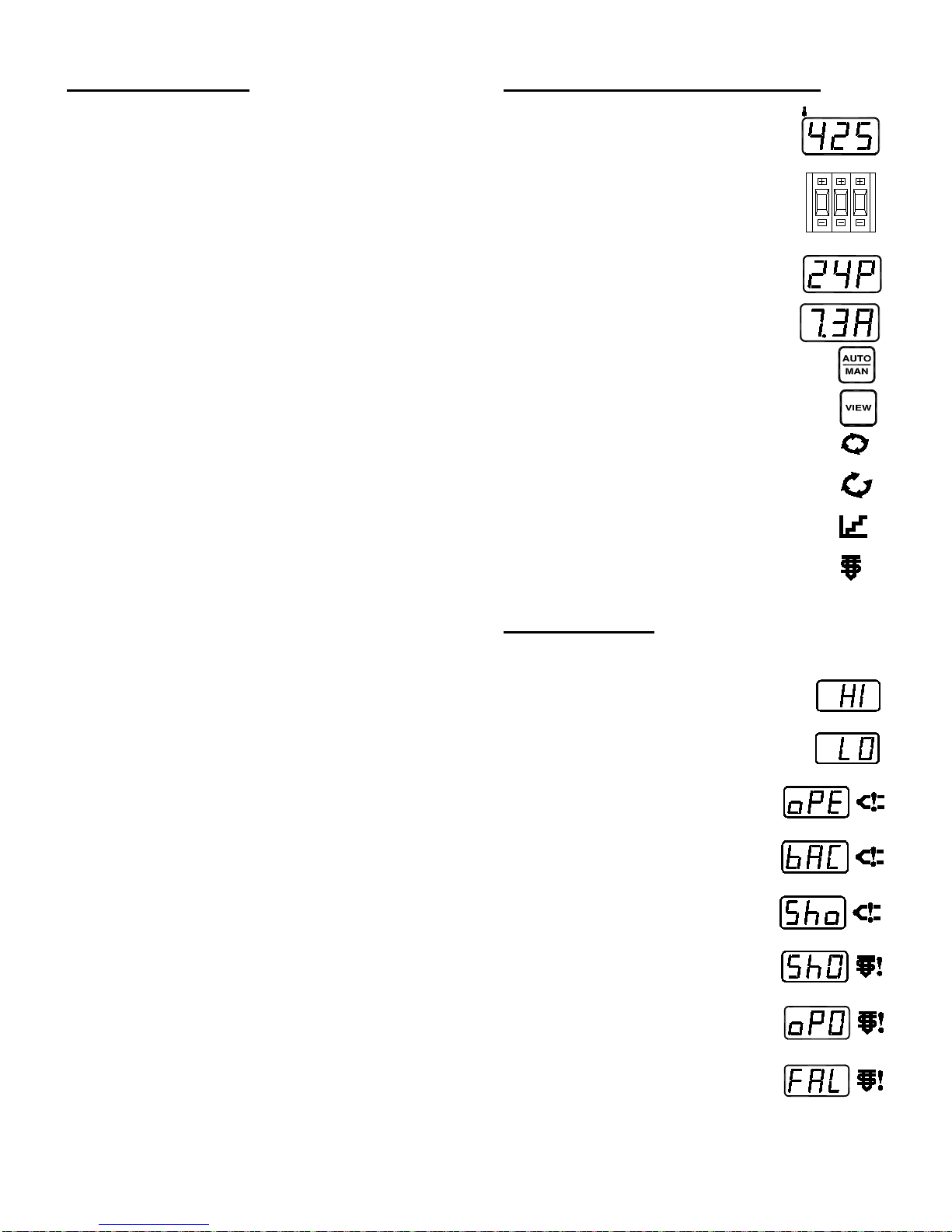
CONTROLS AND INDICATORS
Process Temperature Display ……….....
Setpoint Temperature / Manual Power ...
Power Output (%) Display …………….…
Amps (Load Current) Display ……..……
Control Mode Selection ….……….……...……
Display Output Power (%) & Amps ……….…..
Automatic Mode Indication ……..…………..….
Closed Loop LED Indicator
Manual Mode Indication ………………….……..
Open Loop LED Indicator
Slow Start Mode Indication …………………….
LED Indicator
Load Power Indicator ……………………………
LED Indicator
DIAGNOSTICS
Diagnostics are fully automatic and require no operator
intervention.
Over Temperature Indication
LED Display with Accessory Alarm Output
(+30°F/+17°C)
Under Temperature Indication (-30°F/-17°C)
LED Display with Accessory Alarm Output
Open T/C Indication ……………………
LED Display with Accessory Alarm Output
Reverse T/C Indication …………..……
LED Display with Accessory Alarm Output
Shorted T/C Indication ………………..
LED Display with Accessory Alarm Output
Shorted Output Indication ……………
LED Display with Accessory Alarm Output
Open Output Indication ……………….
LED Display with Accessory Alarm Output
Ground Fault Indication ……..………..
LED Display with Accessory Alarm Output
PCS Company VC-MP 15 Amp Hot Runner Controller Document No.: ED-1503-MN-006-A
User’s Manual October 18, 2016
Page 3 of 15
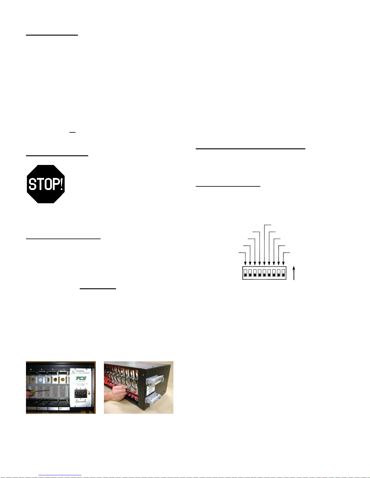
INSPECTION
NOT USED
NOT USED
or
Sho T/C LONG
ACTIVATE
SW4
DIP SWITCHES
AUTO T/C HOLD
°F or °C SCALE
NOT USED
TYPE "J" or "K" T/C
Sho T/C **OFF**
USER SELECTABLE OPTIONS
oPO **OFF**
After removing the VC-MP tem perature controller from
the shipping container im mediately inspect the unit for
damage resulting f rom mishandling in shippi ng. I ns pe ct
for loose components and mechanical damage such as
bent sheet metal, marred front panel screen, etc.
Remove the spare ABC15 fuses and mainframe zone
edge connector contact (required for anti-arc circuit)
and save them for later use.
Note: If the unit appears damaged or the container
is missing components, contact your sales
representative immediately! Use or modification of
the controller or its packaging will decrease the
likelihood of freight claim reimbursement.
INSTALLATION
THIS VC-MP IS EQUIPPED WITH A
HIGH VOLTAGE ANTI-ARC CIRCUI T!
AND IS ENABLED – TO PREVENT
ELECTRICAL DAMAGE TO THE
CONTROLLER IF ACCIDENTALLY
REMOVED FROM THE MAINFRAME WITH
POWER APPLIED.
The controller WILL NOT apply power to
the load unless mainframe zone edge
connector contact #3 is installed.
Inspect each mainframe zone edge connector for the
required contact. If t he contact is not already installed
remove the mainframe rear cover (refer to
manufacturer instructions) and install the contact
supplied with the VC-MP. (Insure contact is locked in
the connector by gently pushing on it from the front.)
Step 1: Verify installation Step 2: If not, install
of contact. provided contact
PCS Company VC-MP 15 Amp Hot Runner Controller Document No.: ED-1503-MN-006-A
User’s Manual October 18, 2016
Page 4 of 15
Note that the contact itself completes the triac gate
(drive) circuit. No wiring, or wire connect ion, is require d
to the #3 edge connector contact.
The anti-arc circuit can be disabled by installing a
#22-28 AWG wire jum per into the printed circuit board
jumper position P5. (S oldering is required. See Fig. 2 ,
Component Layout.)
It is highly recommended that the anti-arc circuit
not be disabled in this manner! If the controller is
inadvertently instal led or removed from the m ainframe
under power it wil l suffer severe dam age, and possib ly
be destroyed. The user is encouraged to take
advantage of this protective feature.
ADVANCED FEATURES
USER SELECTABLE OPTIONS
Many of the advanced f eatur es of the VC-MP controller
must be user selected by setting the DIP switches
SW4 on the main printed ci rcuit boar d. ( Refer to Figure
2, Component Layout.)
Note the following SW4 Factory Default settings:
SW4:1: °F / °C Temperature Scale set °F
SW4:2: Auto T/C Hold set ON
SW4:3: Sho T/C Long Delay set OFF
SW4:4: Sho T/C **OFF** set OFF
SW4:5: Type “J” / “K” Thermocouple set Type “J”
SW4:6: Reserved for Future
SW4:7: oPO (Open Output) Disable set OFF
SW4:8: Reserved for Future
SW4:9: Reserved for Future
Enabling or disabling (on / off) any of these features
must be done before turning the controller power on
(reset). A detailed explan ation of these f eatures follows
below.
 Loading...