

Page 1
PCS 4LHD/4LHDX APPLICATION GUIDE
Ph: 1.804.227.3023 | www.powertraincontrolsolutions.com
Page 2

FORWARD
All information contained in this booklet is based on the latest data available at the time of publication approval. The right
is reserved to make product or publication changes, at any time without notice. Be sure to regularly check for the latest
version, which will be posted on the following website.
https://www.powertraincontrolsolutions.com/latest/documents/
Password: pcs4LHDapp
No part of any PCS publication may be reproduced, stored in any retrieval system, or transmitted in any form by any
means, including but not limited to electronic, mechanical, photocopying, recording, or otherwise without the prior written
permission of Powertrain Control Solutions. This includes all text, illustrations, tables, and charts.
Any comments, questions, requests or to supply updated publication information should be forwarded Powertrain Control
Solutions.
PREFACE
This manual assists the reader in the applications of the 4LHD/4LHDX transmission to vehicle systems. It gives an
overview of the transmission characteristics, as well as focusing on the interface systems between the transmission and
vehicle. The performance of the transmission is dependent on the vehicle design and integration of the interface systems.
This manual is divided into three sections:
Section 1 Transmission Specications and Attributes: Includes guidelines that describe the transmission’s
internal features, external features, performance limitations, and functionality options.
Section 2 Transmission to Vehicle Interfaces: Denes the transmission integration subsystem characteristics,
options, limitations, and integration requirements.
Section 3 Production Line Procedures: Describes transmission installation and transmission handling methods.
Adhering to the requirements set forth in this document is imperative to proper transmission system operation.
All dimensions and values in this manual are for reference only. Refer to the appropriate transmission installation detail
drawing(s) for denitive information.
For more detailed information on the Transmission Control Module (TCM), calibration process, and diagnostic procedures
refer to your TCM manual, as an example the PCS TCM2600 Manual.
For more detailed information on transmission maintenance, diagnostic, and troubleshooting procedures please refer to
the latest version of the PCS 4LHD/4LHDX Technician’s Guide.
Additional information for PCS provided kits and their part numbers are available in the latest version of the PCS OEM
Parts Catalog.
Powertrain Control Solutions
10511 Old Ridge Rd.
Ashland, VA 23005
+1 (804) 227-3023
support@ptcs.us
Page 3

Table of Contents
Section 1: Transmission Specications and Attributes ...................................................................................................................................... 1 - 18
Section 1.1 General Description .................................................................................................................................................................. 1 - 4
Section 1.1.1 Identication ................................................................................................................................................................2
Section 1.1.2 Feature Locations .......................................................................................................................................................3
Section 1.1.3 Gear Ratios .................................................................................................................................................................4
Section 1.2 Physical Specications ............................................................................................................................................................. 4 - 7
Section 1.2.1 Mass Properties ..........................................................................................................................................................4
Section 1.2.2 Driveline Lengths ........................................................................................................................................................5
Section 1.2.3 Center of Gravity ................................................................................................................................................... 6 - 7
Section 1.2.4 Inertia Properties .........................................................................................................................................................7
Section 1.2.4 Gross Vehicle Weight (GVW) ......................................................................................................................................7
Section 1.3 Maximum Performance Limitations .........................................................................................................................................8 - 11
Section 1.3.1 Torque Limitations .......................................................................................................................................................8
Section 1.3.2 RPM Limitations ..........................................................................................................................................................9
Section 1.3.3 Acceleration Limitations ..............................................................................................................................................9
Section 1.3.4 Temperature Limitations ............................................................................................................................................10
Section 1.3.5 Grade Limitations ......................................................................................................................................................11
Section 1.4 Valvebody Features and Specifcations ........................................................................................................................................12
Section 1.4.1 Abuse Protection .......................................................................................................................................................12
Section 1.4.2 Neutral Idle ................................................................................................................................................................12
Section 1.4.3 Electronic Range ........................................................................................................................................................12
Section 1.4.4 Inching Mode .............................................................................................................................................................12
Section 1.5 Electrical Specications ........................................................................................................................................................ 13 - 18
Section 1.5.1 Solenoids .......................................................................................................................................................... 13 - 16
Section 1.5.2 Internal Wiring ................................................................................................................................................... 17 - 18
Section 2: Transmission to Vehicle Interfaces .................................................................................................................................................... 19 - 69
Section 2.1 Transmission Input ............................................................................................................................................................... 19 - 30
Section 2.1.1 Torque Converters ............................................................................................................................................. 19 - 23
Section 2.1.2 Flexplate ....................................................................................................................................................................24
Section 2.1.3 Flywheel Interface .....................................................................................................................................................25
Section 2.1.4 Bellhousing to Flywheel Housing Interface ....................................................................................................... 26 - 30
Section 2.2 Transmission Output ............................................................................................................................................................ 31 - 39
Section 2.2.1 Lubrication and Sealing .............................................................................................................................................31
Section 2.2.2 Output Shaft Requirements ............................................................................................................................... 31 - 32
Section 2.2.3 Extension Housings .......................................................................................................................................... 32 - 39
Section 2.3 Transmission Cooling .......................................................................................................................................................... 40 - 52
Section 2.3.1 Cooling System Overview .........................................................................................................................................40
Section 2.3.2 Cooler Requirements .................................................................................................................................................41
Section 2.3.3 Cooler Lines ...................................................................................................................................................... 41 - 42
Section 2.3.4 Dipstick ......................................................................................................................................................................43
Section 2.3.5 Overow Vent ............................................................................................................................................................44
Page 4

Table of Contents
Section 2.3.6 Fluid Capacity ...........................................................................................................................................................45
Section 2.3.7 Check Fluid Level .............................................................................................................................................. 45 - 47
Section 2.3.8 Fluid Change ..................................................................................................................................................... 48 - 52
Section 2.4 Transmission Shift Lever ..................................................................................................................................................... 53 - 60
Section 2.4.1 Shaft Specs ...............................................................................................................................................................54
Section 2.4.2 Lever Specs ....................................................................................................................................................... 55 - 58
Section 2.4.3 Electronic Range ................................................................................................................................................ 59 - 60
Section 2.5 TCM Interface ....................................................................................................................................................................... 61 - 67
Section 2.5.1 TCM Overview .................................................................................................................................................. 61 - 62
Section 2.5.2 Vehicle Electrical Interface and Diagnostics ...................................................................................................... 63 - 66
Section 2.5.3 Harness Overview .....................................................................................................................................................67
Section 2.6 Throttle Position Sensor ....................................................................................................................................................... 68 - 69
Section 3: Production Line Procedures ............................................................................................................................................................... 70 - 73
Section 3.1 Assembly Procedures ........................................................................................................................................................... 70 - 71
Section 3.1.1 Storage Requirements ..............................................................................................................................................70
Section 3.1.2 Handling Requirements .............................................................................................................................................70
Section 3.1.3 Assembly Requirements ...........................................................................................................................................71
Section 3.2 End-of-Line Inspection Procedures ..................................................................................................................................... 72 - 73
Section 3.2.1 Pre-Start Checks .......................................................................................................................................................72
Section 3.2.2 Stationary Engine-Off Checks ...................................................................................................................................72
Section 3.2.3 Stationary Engine-Running Checks ...........................................................................................................................73
Section 3.2.4 Test Drive ..................................................................................................................................................................73
Section 3.2.5 Post Drive Check ......................................................................................................................................................73
Revision History
03-09-2016 - REV 1.0: Original Release
05-11-2016 - REV 1.1: Addition of torque specications for extension housing, line pressure tap tting, cooler lines, and bellhousing.
Page 5

SECTION 1
TRANSMISSION SPECIFICATION
AND ATTRIBUTES
Page 6
Powertrain Control Solutions
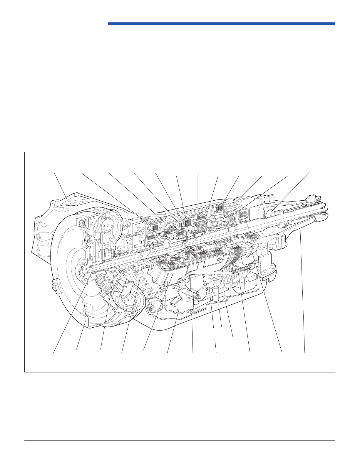
CASE
ASSEMBLY
REVERSE
INPUT CLUTCH
INPUT CLUTCH
HOUSING
OVERRUN
CLUTCH
FORWARD
CLUTCH
FORWARD
SPRAG CL
ASSEMBLY
3-4
CLUTCH
INPUT
PLANETARY
GEARSET
LO AND
REVERSE
CLUTCH
TORQUE
CONVERTER
ASSEMBLY
STATOR
ROLLER
CLUTCH
PUMP
ASSEMBLY
LO ROLLER
CLUTCH
ASSEMBLY
REACTION
PLANETARY
GEARSET
TURBINE
SHAFT
2-4
BAND
ASSEMBLY
INSIDE
DETENT LEVER
MANUAL
SHAFT
CONTROL VALVE
ASSEMBLY
PARKING LOCK
ACTUATOR ASSEMBLY
OUTPUT
SHAFT
PARKING
PAWL
SPEED
SENSOR
Section 1. Transmission Specications and Attributes
1.1 General Description
The 4LHD/4LHDX is a fully automatic, electronically controlled, RWD/4WD transmission. It consists primarily of a three
element hydraulic torque converter with a converter clutch, two planetary gear sets, various clutches, an oil pump, and
a control valve body. There are four forward driving gear ranges in addition to neutral, reverse, and park. The torque
converter clutch is available in 2nd, 3rd, and 4th (overdrive) gear. Park range is available in applications that do not
exceed the GVW ratings provided in Section 1.2.5. The mass of a complete system package is estimated to be between
87-113 kg (192-250 lb). This does not include cooler lines, radiator, uid within the external cooling system, shifter cable,
shifter bracket assembly, rear transmission mount isolator, external sensors (such as TPS), and otherwise anything else
vehicle specic not included in Section 1.2.1.
Figure 1.1-1
Abuse
Protection
Solenoid
Abuse
Protection
Solenoid
Page 1
REV 1.1
10511 Old Ridge Rd. Ashland, VA 23005
Ph: 804.227.3023
Page 7
4LHD/4LHDX Application Manual
4.4. Transmission and Vehicle Identification
4.4.1. VIN
The following procedure is recommended for VIN operation. Typical locations are shown
in Figure 4.4.1-1.
1. Scan bar-code on transmission.
2. Place etcher on transmission in designsted GMPT approved VIN number area or
use hand stamp and imprint VIN number into transmission in designated GMPT
approved area.
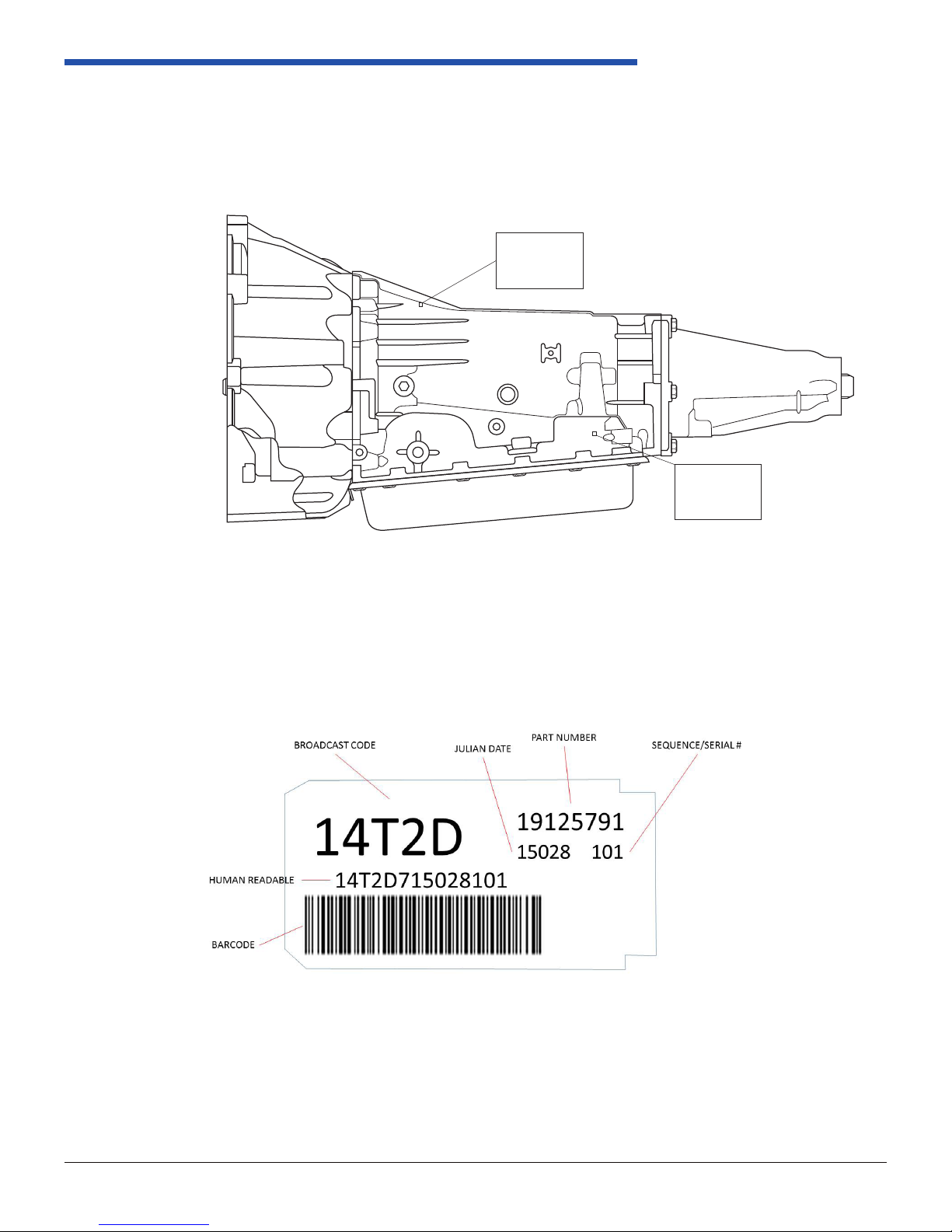
1.1.1 Identication
The transmission nameplate is used to identify the transmission model as well as build date and manufacturing site. A
typical nameplate is shown and dened in Figure 1.1.1-2.
Located on
top side of
transmission
Behind TCM
bracket on
LH side
Figure 1.1.1-1 Transmission I.D. Nameplate Locations
Figure 1.1.1-2 Transmission I.D. Nameplate Features
Page 2
REV 1.1
10511 Old Ridge Rd. Ashland, VA 23005
Ph: 804.227.3023
Page 8
Powertrain Control Solutions
ATTACHMENT
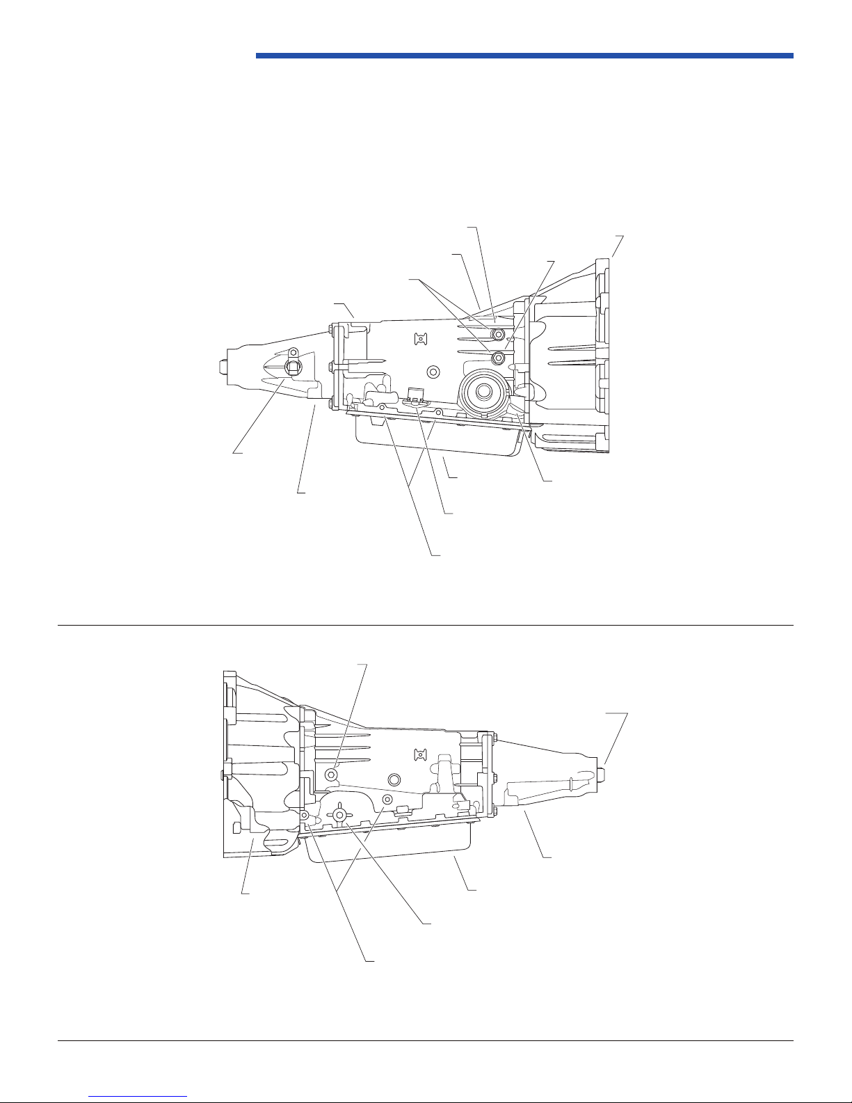
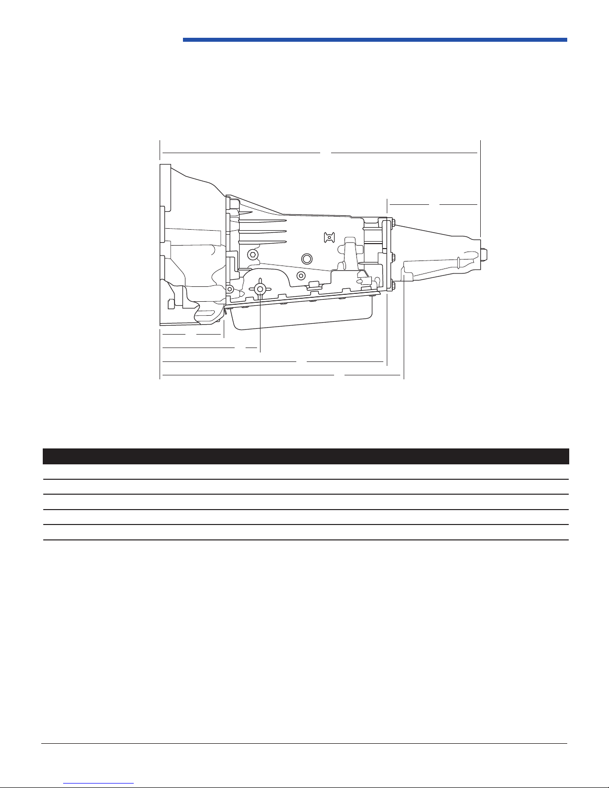
1.1.2 Feature Location Illustrations
The following gures show all external components and their locations on the transmission case. Manual shaft, uid
level screw, vent cap, output vehicle speed sensor, bottom pan, electrical pass-through connector, cooler line attachment
interface and powertrain mount boss provisions are shown in these diagrams.
FLARE OR QUICK CONNECT
TRANSMISSION CASE
➤
➤
SPEED
SENSOR
VEHICLE
MOUNTING PAD
FROM COOLER
AIR BREATHER (VENT)
➤
➤
➤
➤
TO COOLER
➤
➤
➤
➤
➤
TRANSMISSION
OIL PAN
TRANSMISSION CONTROL
CONNECTOR
HEAT SHIELD LOCATION (S)
ENGINE FACE
➤
➤
➤
FILL TUBE
HOLE
Figure 1.1.2-1: PCS 4LHD/4LHDX with GM GEN III Bellhousing and 2WD Extension Housing (Right Side View)
Page 3
LINE
PRESSURE
TAP
OUTPUT
SHAFT
➤
➤
TORQUE
CONVERTER
➤
➤
➤
➤
➤
TRANSMISSION OIL PAN
TRANSMISSION SHIFT LEVER
(MANUAL SHAFT)
ATTACHMENT BOSSES FOR
EXTERNAL POSITION SWITCH
➤
CASE
EXTENSION
Figure 1.1.2-2: PCS 4LHD/4LHDX with GM GEN III Bellhousing and 2WD Extension Housing (Left Side View)
REV 1.1
10511 Old Ridge Rd. Ashland, VA 23005
Ph: 804.227.3023
Page 9

1.1.3 Gear Ratios
Gear Ratio
1st 3.059:1
2nd 1.625:1
3rd 1.000:1
4th 0.696:1
Reverse 2.294:1
1.2 Physical Specications
1.2.1 Mass Properties
Transmission Mass As Installed
4LHD/4LHDX 75 kg (165 lbs)*
* This can vary +/- 3kg (6.6lbs) based on torque converter and output shaft
4LHD/4LHDX Application Manual
Bellhousing Mass As Installed
GM Gen III 4.9 kg (10.8 lbs)
C6 Replacement 5.2 kg (11.5 lbs)
SAE3 5.2 kg (11.5 lbs)
SAE4 4.5 kg (9.9 lbs)
SAE5 7.3 kg (16.1 lbs)
Extension Housing Mass As Installed
GM 2WD 1.8 kg (4.0 lbs)
GM 4WD 2.4 kg (5.3 lbs)
PCS Parking Brake 10.2 kg (22.5 lbs)*
C6 Replacement 4.3 kg (10.1 lbs)**
* Mass measured without drive shaft ange
** Mass measured without C6 brake housing and drum brakes
Accessory Mass As Installed
Transmission Harness 0.7 kg (1.6 lbs)*
Dipstick Kit 0.4 kg (0.9 lbs)
Heat Shield Kit 0.4 kg (0.9 lbs)
Controller (TCM) 0.3 kg (0.7 lbs)
TCU Bracket Kit 0.5 kg (1.1 lbs)
Overow Vent Kit 0.2 kg (0.5 lbs)
Flexplate Kit 1.8 kg (4.0 lbs)
Flywheel Adapter 8.8 kg (19.4 lbs)**
* This can vary +/- 0.3kg (0.7lbs) based on vehicle application
** This can vary +/- 4.0kg (8.8lbs) based on ywheel application
Page 4
REV 1.1
10511 Old Ridge Rd. Ashland, VA 23005
Ph: 804.227.3023
Page 10
Powertrain Control Solutions
1.2.2 Driveline Lengths
For an example, the following dimensions are based on the GM 2WD extension housing. For other extension housing
lengths, reference Section 2.2.3.
➤
D
➤
TRANSMISSION ASM.
(TWO-PIECE CASE)
2WD
➤
➤
➤
➤
Figure 1.2.2-1: PCS 4LHD/4LHDX with GM GEN III Bellhousing and 2WD Extension Housing Dimensions
➤
A
➤
B
E
C
➤
➤
➤
F
➤
Type DIM (mm) A B C D E F
GM GEN III Bell 176.3 259.2 618.0 794.3 568.0 226.3
C-6 Bell 142.3 225.2 584.0 760.3 534.0 266.3
SAE 3 Bell 189.0 271.9 630.7 807.0 580.7 266.3
SAE 4 Bell 189.0 271.9 630.7 807.0 580.7 266.3
SAE 5 Bell 189.0 271.9 630.7 807.0 580.7 266.3
A = Bellhousing Length
B = Engine Face to Manual Shaft Distance (C = Engine Face to Vehicle Mount Distance)
C = Engine Face to Vehicle Mount Distance
D = Overall Length (Engine Face to Rear Face of Extension)
E = Length of Case Dimension
F = Length of Extension Housing
Page 5
REV 1.1
10511 Old Ridge Rd. Ashland, VA 23005
Ph: 804.227.3023
Page 11
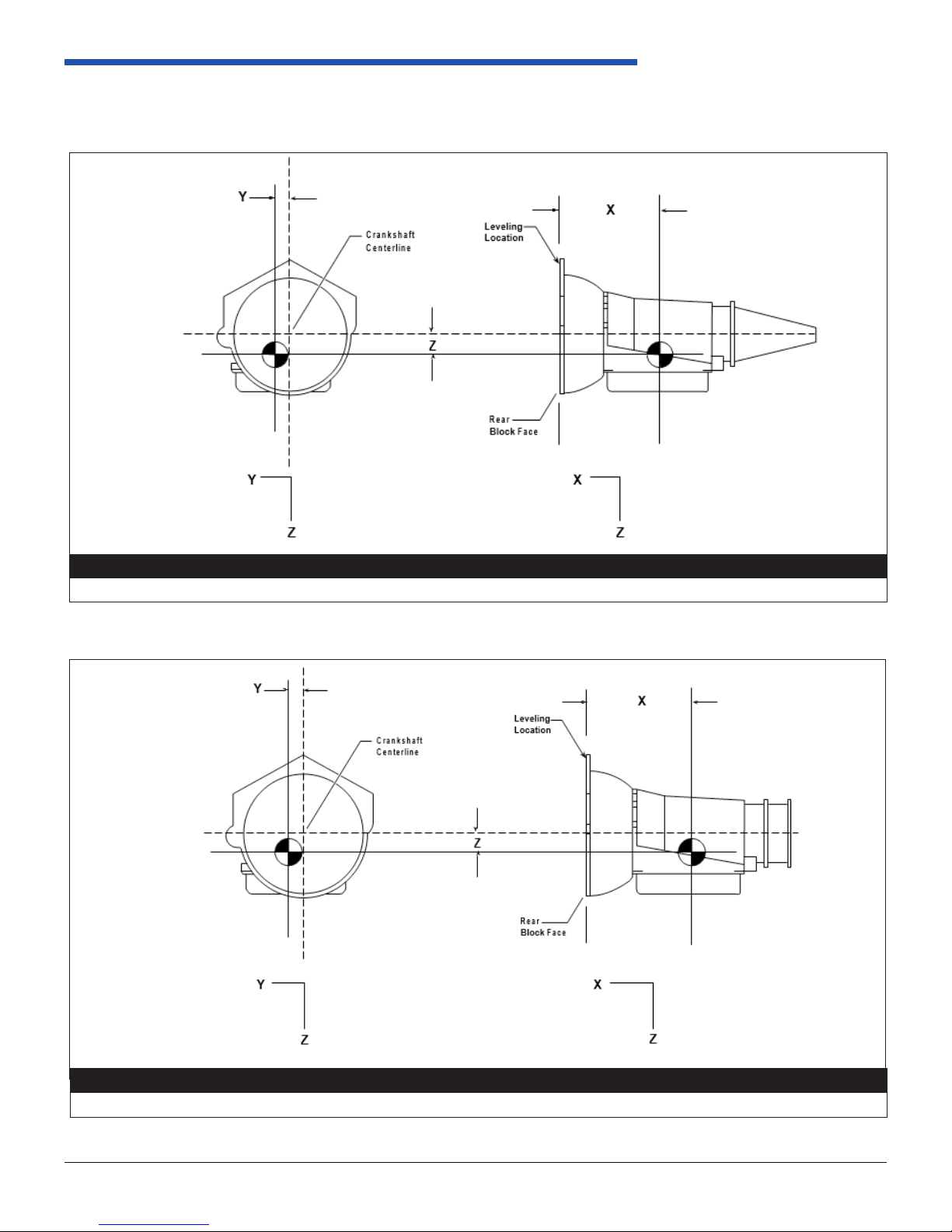
1.2.3 Center of Gravity
4LHD/4LHDX Application Manual
Object Weight X Y Z
83.9 kg (185.00 lb) -253 mm (-9.96 in) 3 mm (.12 in) 17 mm (.67 in)
Figure 1.2.3-1 4LHD/4LHDX with 2WD Extension Housing
Object Weight X Y Z
85.28 kg (188.00 lb) -251 mm (-9.90 in)
Figure 1.2.3-2 4LHD/4LHDX with 4WD Extension Housing
Page 6
10 mm (.40 in) 18 mm (.70 in)
REV 1.1
10511 Old Ridge Rd. Ashland, VA 23005
Ph: 804.227.3023
Page 12

Powertrain Control Solutions
1.2.3 Center of Gravity Cont’d
Approximate location of CG; actual location will depend on transmission model. Contact PCS if actual is desired.
258 mm Torque Converter
2WD 4WD
X -253 mm -251 mm
Y 3 mm 10 mm
Z 17 mm 18 mm
1.2.4 Inertia Properties
Approximate location of CG; actual location will depend on transmission model. Contact PCS if actual is desired.
Rotational Inertia
lxx = 0.94 kg-m
lyy = 2.93 kg-m
lzz = 2.99 kg-m
2
2
2
Approximate values, dependent on transmission model.
Reference: SAE Engine Coordinate System or gures found in Section 1.2.3-1
Rotational Inertia
1st gear 0.0547 kg-m
2nd gear 0.039616 kg-m
3rd gear 0.02553 kg-m
4th gear 0.06692 kg-m
Referred to the input shaft of the transmission without torque converter, transfer case, or parking brake.
2
2
2
2
1.2.5 Gross Vehicle Weight
GVW
3,900 kg (8,600 lb) maximum*
*This gure is limited by the strength of the parking pawl. If other parking mechanisms are utilized, and the transmission is not shifted into park, higher
GVWs are possible. Contact PCS for vehicle calculations in this case.
Page 7
REV 1.1
10511 Old Ridge Rd. Ashland, VA 23005
Ph: 804.227.3023
Page 13

1.3 Maximum Performance Limitations
1.3.1 Torque Limitations
Engine Input Torque
4LHD with 258 MM Converter - 340 Nm (250 lb-ft) Maximum
4LHDX with 300 MM Converter - 542 Nm (400 lfb-ft) Maximum
Gearbox Input Torque
4LHD with 258 MM Converter - 660 Nm (487 lb-ft) Maximum
4LHDX with 300 MM Converter - 1057 Nm (780 lb-ft) Maximum
Torque Converter Capacity - Speed
258 mm: 7,000 RPM @ 690 kPa (100 psi), 6500 RPM @ 1020 kPa (150 psi)
300 mm: 7,000 RPM @ 900 kPa (130 psi)
Torque Converter Capacity - Input Torque
258 mm: 340 Nm (250 lb-ft)
300 mm: 542 Nm (400 lb-ft)
4LHD/4LHDX Application Manual
Torque Converter Capacity - Stall Power
258 mm: 79.1 kW (106 hp)
300 mm: 124.6 kW (167 hp)
NOTE: Values @ 690 kPa (100 psi), increase limit by 0.75 kW/14 kPa (1 hp/psi), not to exceed 1020 kPa (150 psi).
To calculate stall power:
(engine stall speed) x (engine torque at stall)
9546
Torque Converter Capacity - Turbine Torque
258 mm: 632 Nm (392 lb-ft)
300 mm: 943 Nm (696 lb-ft)
NOTE: Must verify adequate spline engagement. Reference Section 2.1.1.
Calculated: (engine torque) x (converter ratio)
Torque Converter Capacity - Stator Torque
258 mm: 340 Nm (250 lb-ft)
300 mm: 542 Nm (400 lb-ft)
Calculated: (engine torque) x [ (converter ratio) - 1 ]
Torque Converter Capacity - Max TCC Apply Pressure
258 mm: 930 kPa (135 psi)
300 mm: 862 kPa (125 psi)
Minimum pressure, all operating conditions 415 kPa (60 psi).
Page 8
REV 1.1
10511 Old Ridge Rd. Ashland, VA 23005
Ph: 804.227.3023
Page 14

Powertrain Control Solutions
1.3.2 RPM Limitations
Maximum Speed in Park and Neutral
Maximum engine speed cannot exceed 4,000 RPM when the transmission is in park or neutral.
Maximum Shift Speed
The maximum shift speed allowed is application dependent. Note: These maximum shift speeds are dependent on
nal drive ratio, torque converter stall torque ratio, and the engine torque curve prole. Consult with Powertrain Control
Solutions for application specic maximum shift speeds.
Minimum Engine Idle Speed
600 RPM when ATF is above 115˚C (240˚F)
550 RPM when ATF is 0˚C to 115˚C (32˚F to 240˚F)
700 RPM when ATF is below 0˚C (32˚F)
Minimum TCC Apply
Minimum TCC apply speeds are dictated by powertrain and chassis response in the following ranges at normal operating
temperatures.
Engine Engine RPM (Light Throttle) Engine RPM (Heavy Throttle)
All 1000 1800
Maximum Output Speed
Maximum output speed is 7,200 RPM.
Maximum Vehicle Speed
Maximum vehicle speed is dependent on nal drive ratio, torque converter ratio and engine torque curve prole. Powertrain
Control Solutions must be consulted for application specic maximum speeds.
1.3.3 Acceleration Limitations
The 4LHD/4LHDX automatic transmission has been tested for longitudinal and lateral acceleration capability in vehicles
under the following maneuvers at the entire temperature range:
W.O.T. acceleration on level road. Panic stop from 30 mph followed by W.O.T. acceleration.
Longitudinal
Lateral
Gradual stop from 30 mph followed by W.O.T. acceleration.
Right turn at 20 mph with W.O.T. acceleration. Left turn at 20 mph with W.O.T. acceleration. Right
turn panic stop from 20 mph. Left turn panic stop from 20 mph. Continuous right turn at 60 ft turning
radius. Continuous left turn at 60 ft turning radius.
*W.O.T = Wide Open Throttle
Page 9
REV 1.1
10511 Old Ridge Rd. Ashland, VA 23005
Ph: 804.227.3023
Page 15

4LHD/4LHDX Application Manual
1.3.4 Temperature Limitations
Functional Range: -40˚C to 55˚C (-40˚F to 131˚F)
Dened as the ambient range where the vehicle will function without causing transmission operational concerns or thermal
distress in adequately cooled installations.
Underbody Temperature
Life of the transmission gaskets, seals and connectors is affected by elevated temperatures. Airow around the
transmission and the proximity to heat sources such as catalytic converter or exhaust system inuence the temperature
build up at the transmission surface. It should be noted that shift cable systems are also sensitive to heat, and should be
routed to avoid extreme temperatures.
Temperatures shall be monitored during testing to ensure appropriate temperature levels. A thermal packaging study is
recommended to verify all underbody temperatures.
Component Skin Temperature Limits
The following maximum temperatures are based on released component materials. These temperatures must not be
exceeded during test.
Exposed Area Maximum Continuous Maximum Excursion
External Seals 138°C (280°F) 150°C (302°F)
Oil Pan Gasket 138°C (280°F) 150°C (302°F)
Trans. Based on Non Metallic Connectors 138°C (280°F) 138°C (280°F)
Trans. Electrical Terminals 135°C (275°F) 135°C (275°F)
Trans. Wiring Harness 125°C (257°F) 125°C (257°F)
Controller (TCM) 105°C (221° F) 125°C (257°F)
* Reference Section 2.3 for cooler requirements and transmission sump operating temperatures.
Page 10
REV 1.1
10511 Old Ridge Rd. Ashland, VA 23005
Ph: 804.227.3023
Page 16
Powertrain Control Solutions
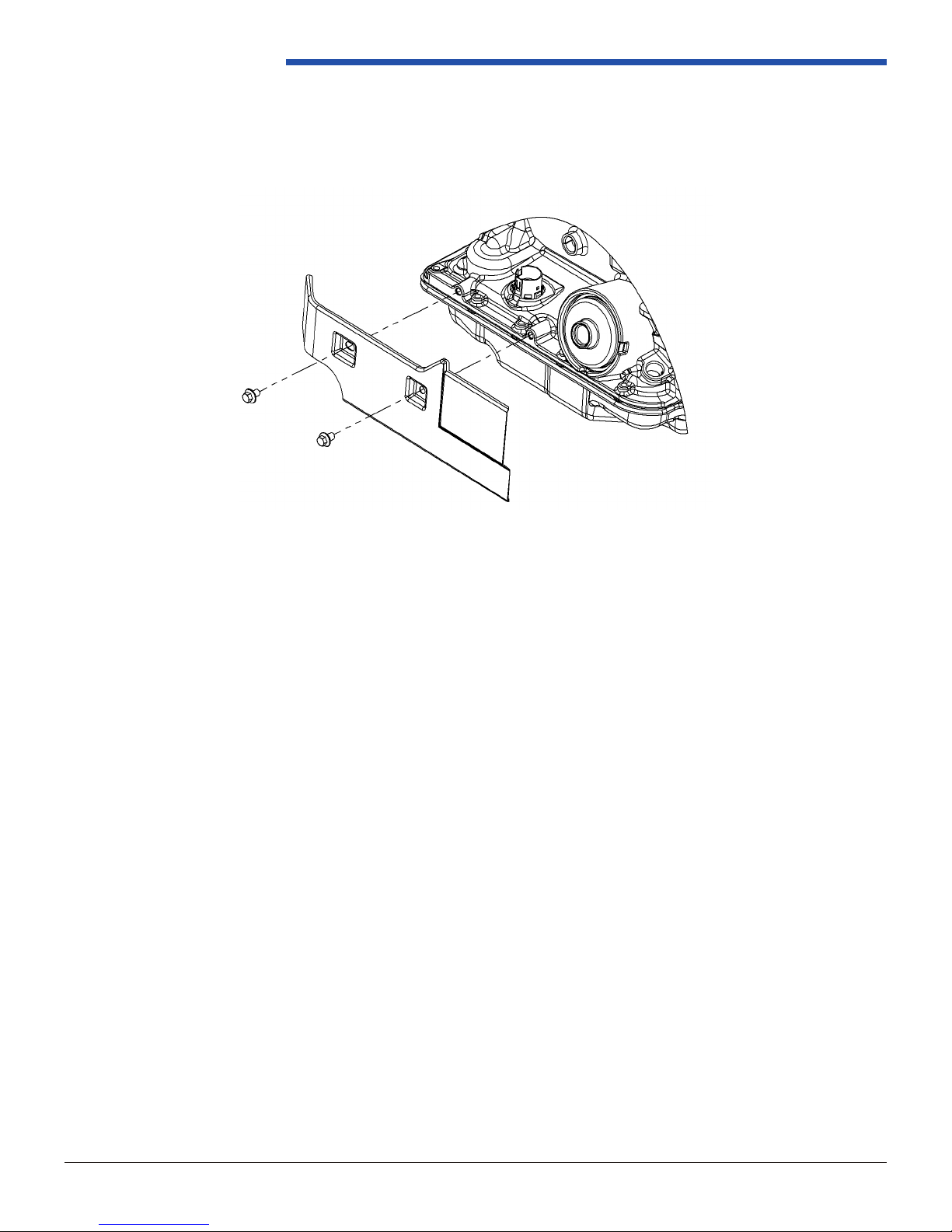
Heat Shield
Shown in Figure 1.3.4-1 is an available heat shield that protects the gasket, connector, and accumulator from common
exhaust positions. Consult with PCS if this is necessary or adequate for your application.
Figure 1.3.4-1: Heat Shield Exploded View
1.3.5 Grade Limitations
Maximum Grade for Hydraulic Operation
This transmission is validated to operate on longitudinal and lateral slopes of up to 30% (16.7 degree grade) without
detrimental effect on the operation of the hydraulic system at normal working temperature. Consult with Powertrain
Control Solutions if the proposed application exceeds these values.
Maximum Grade for Park System
There is a maximum grade capability of 30% (16.7 degree grade) for park pawl engagement with both the park mechanism
engaged and the parking brake on.
Page 11
REV 1.1
10511 Old Ridge Rd. Ashland, VA 23005
Ph: 804.227.3023
Page 17
4LHD/4LHDX Application Manual
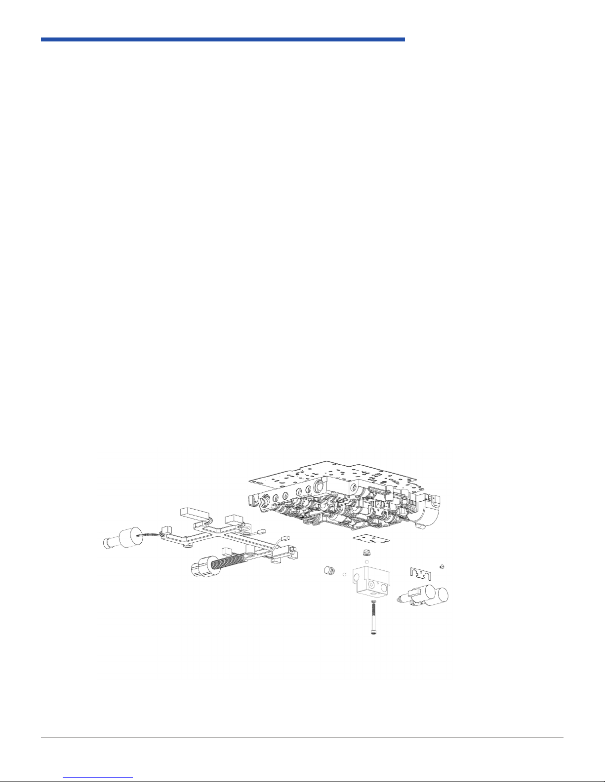
1.4 Valve body Features and Specications
The following are valve body options. When ordering from PCS, you must specify your desired valve body conguration.
1.4.1 Abuse Protection
Often times the operator causes the most damage to the transmission, reducing the service life and causing
costly repairs and downtime. The PCS 4LHD/4LHD-X abuse protection valve body protects the transmission by
locking out reverse engagement until the vehicle is stopped and the engine is at idle. It also prevents “neutral
drops” by only engaging the forward gears when the engine is at idle.
1.4.2 Neutral Idle
As an option, the PCS valve body can disengage the forward gears when the vehicle is stopped and the brake
pedal is pressed. By reducing the number of rotating components during idle, fuel consumption can be reduced
especially for vehicles that spend a lot of time idling in gear. With the forward gears disengaged, the reduced
brake force required to hold the vehicle, especially in high gear reduction drivelines, can signicantly improve the
drivability of the vehicle from the operator’s perspective.
1.4.3 Electronic Range (Option)
This allows you to eliminate the shift cable and shift the transmission electronically with a push button or a
movement of a lever. Driver inputs can be validated based on vehicle modes and conditions so the vehicle is
operated within standard operating protocols. Also eliminate transmission failures due to the shift cable not
adjusted properly. Reference Section 2.4.3 for external setup.
1.4.4 Inching Mode (Option)
The PCS inching valve body allows the operator to move the vehicle forward or backward in small increments
from an operator’s panel remotely mounted on the vehicle. This greatly reduces time when connecting to trailers
or other equipment and makes the operation more efcient for one person.
Page 12
Figure 1.4-1: PCS Valve Body Explosion View
REV 1.1
10511 Old Ridge Rd. Ashland, VA 23005
Ph: 804.227.3023
Page 18

Powertrain Control Solutions
1.5 Electrical Specications
1.5.1 Solenoids
Shift
Range Gear
Park
Reverse
Neutral
OD
D
2
1
1. Shift solenoid state is a function of vehicle speed and may change if vehicle speed increases.
2. Manual Second - First gear is electronically prevented under normal operating conditions.
3. Solenoid state will be opposite shown during abuse protection
2nd OFF ON ON 3OFF Applied Applied Holding
2nd OFF ON ON 3OFF Applied Applied Holding
1st 2ON ON ON 3OFF Applied Applied Holding Holding
2nd OFF ON ON 3OFF Applied Applied Applied Holding
2nd OFF ON ON 3OFF Applied Applied Applied Holding
Solenoid
1-2 2-3 FWD REV
ON 1ON 1OFF OFF Applied
ON 1ON 1ON ON
ON 1ON 1ON ON
1st ON ON ON 3OFF Applied Holding Holding
3rd OFF OFF ON 3OFF Applied Holding Applied
4th ON OFF ON 3OFF Applied Applied Applied
1st ON ON ON 3OFF Applied Holding Holding
3rd OFF OFF ON 3OFF Applied Applied Holding Applied
1st ON ON ON 3OFF Applied Applied Holding Holding Applied
Abuse
Solenoid
Reverse
2-4
Band
3
Input
Clutch
Applied Applied
Overrun
Clutch
Forward
Clutch
Forward
Sprag CL.
Assembly
3-4
Clutch
LO/
Roller
Clutch
LO/REV
Clutch
Shift Solenoids
The two identical shift solenoids are two port, on/off solenoids (normally on) that are used to control the shift
change events.
• The shift solenoid coil resistance should be 20-40 ohms at 20.0 +/- 5.0°C.
• The shift solenoid current ow should not exceed 0.75 Amps.
• The shift solenoid energizes at 7.5 volts or more.
• The shift solenoid de-energizes at 1.0 volts or less.
TCC Enable Solenoid
The TCC Enable Solenoid is a two port, on/off solenoid (normally on) that is used to apply and release pressure
to the Torque Converter Clutch.
• The TCC Enable Solenoid coil resistance should be 20-40 ohms at 20.0 +/- 5.0°C.
• The TCC Enable Solenoid current should not exceed 1.5 Amps.
TCC Control Solenoid
The TCC Control Solenoid is a three port (normally closed) device used to control the apply and release pressure
of the Torque Converter Clutch. Adujsting this in the TCU Calibration changes the shift rmness of the Torque
Converter Clutch.
• The TCC Control Solenoid operates at a xed frequency (negative duty cycle) of 32 Hz.
• The TCC Control Solenoid coil resistance should be 10.0 - 11.5 Ohms when measured at 20.0 +/- 5.0°C.
Page 13
REV 1.1
10511 Old Ridge Rd. Ashland, VA 23005
Ph: 804.227.3023
Page 19

4LHD/4LHDX Application Manual
➤
TIME
VOLTS
12
0
1 CYCLE = 1/292.5 SECOND
➤
➤
40%
60%
➤
➤
➤
➤
➤
(ON)
PRESSURE CONTROL SOLENOID VALVE POSITIVE DUTY CYCLE
PRESSURE CONTROL SOLENOID VALVE
➤
➤
➤
➤
➤
➤
➤
➤ ➤ ➤
➤
➤ ➤ ➤
➤
➤
➤
➤
➤
➤ ➤ ➤ ➤
➤
➤
➤
➤
➤
➤
➤
PUSH
ROD
FRAMESPRING
SPOOL
VALVE
ACTUATOR
FEED
LIMIT
FLUID
TORQUE
SIGNAL
FLUID
COIL
ASSEMBLY
EXHAUST ARMATURE
DAMPER
SPRING
FLUID
SCREENS
SPOOL
VALVE
SPRING
VARIABLE
BLEED
ORIFICE
SPOOL
VALVE
SLEEVE
PLNGR
54
54
54
21
CNTRL
PRESS
SHIFT
20
21
9
54
54
54
54 54
SHIFT
PRESSURE CONTROL
SOLENOID VALVE
(SLS) (340)
1111
11
FLUID PRESSURE
TEST HOLE PLUG (334)
SHIFT PRESSURE CONTROL SOLENOID VALVE (SLS)
EXHAUST
EXHAUST
CONNECTOR
COIL
ASSEMBLY
SPOOL
VALVE
SPRING
PLUNGER
PRESSURE
SUPPLY
(SOLENOID
MODULATOR)
PRESSURE
CONTROL
(SHIFT
CONTROL)
VALVE
Abuse Protection Solenoid (Non-Electronic Range)
The identical Forward/Reverse Abuse Protection Solenoids (Non-ER) three port linear pressure control solenoids
(normally open).
• The Non-ER Forward/Reverse solenoids coil resistance is 5.0-5.6 ohms at 25.0 +/- 1.0°C.
• The Non-ER Forward/Reverse solenoids operate at a xed frequency of 300Hz.
160
140
120
100
80
60
Abuse Protection Solenoid (Electronic Range)
The two identical ER Forward/Reverse Abuse Protection solenoids are three port PWM (Pulse Width Modulation)
solenoids (normally closed).
• The ER Forward/Reverse solenoids operate at a xed frequency (negative duty cycle) of 32 Hz.
• The ER Forward/Reverse solenoids coil resistance should be 10.4-10.8 Ohms when measured at 20.0 +/- 5.0°C
• The ER Forward/Reverse solenoids coil resistance should be approximately 16 Ohms when measured at 150 +/-
5.0°C.
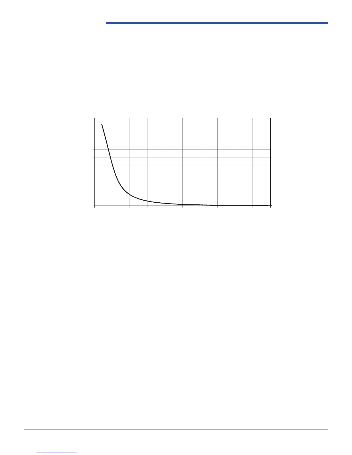
Pressure Control Solenoid
The Pressure Control Solenoid is a three port electronic pressure regulator used to control line pressure. When the
solenoid is off, line pressure is unrestricted from the line pressure pump. When the solenoid is on, line pressure is
restricted to the values shown in the chart. A line pressure tap is available. The torque rating for this tting is 8 lb*ft / 11
N*m. Reference Figure 2.4.6.1-3.
• The Pressure Control Solenoid operates at a xed frequency of 292.5 Hz.
• The Pressure Control Solenoid coil resistance is 3.5-4.6 Ohms at 20.0 +/- 5.0°C.
40
CONTROL PRESSURE (PSI)
20
0
0.0
Figure 1.5.1-1: Abuse Protection Solenoid Valve Current Flow
100
90
80
70
60
0.1 0.2 0.3 0.4
50
40
30
20
CONTROL PRESSURE (PSI)
10
0
0.0
Figure 1.5.1-2: Pressure Control Solenoid Valve Current Flow
INPUT CURRENT (AMP)
0.1 0.2 0.3 0.4
0.60.5 0.7 0.8 0.9
0.60.5 0.7 0.8 0.9
INPUT CURRENT (AMP)
1.0 1.1
1.0 1.1
Page 14
REV 1.1
10511 Old Ridge Rd. Ashland, VA 23005
Ph: 804.227.3023
Page 20
TEMPERATURE SENSOR
VEHICLE SPEED SENSOR
FIGURE A: CONDITIONED SIGNAL
OUTPUT VOLTS
LOW SPEED
➤
5.0
HIGH SPEED
TIME
-50 -30 -10 10 30 50 70 90 110 130 150
110
100
90
80
70
60
50
40
30
20
10
0
Sensor Resistance (K ohms)
Temperature C
SENSOR RESISTANCE VS. TEMPERATURE
CONNECTOR RESISTOR
TRANSMISSION
FLUID PRESSURE
MANUAL VALVE
POSITION SWITCH
ASSEMBLY (69)
ELECTRICAL
CONNECTOR
MAGNETIC PICKUP
TRANSMISSION FLUID TEMPERATURE (TFT) SENSOR
The temperature sensor is a negative temperature coefficient
thermistor (temperature sensitive resistor) that provides
information to the PCM regar ding transmission fluid
temperature. The temperature sensor is a part of the
transmission fluid pressure (TFP) manual valve position switch
assembly which is attached to the control valve body and
submersed in fluid in the transmission bottom pan. The
internal electrical resistance of the sensor varies in relation to
the operating temperature of the transmission fluid (see chart).
The PCM sends a 5 volt reference signal to the temperature
sensor and measures the voltage drop in the circuit. A lower
fluid temperature creates a higher resistance in the temperature
sensor, thereby measuring a higher voltage signal.
The PCM measures this voltage as another input to help
control TCC apply and line pressure. The PCM inhibits
TCC
apply until transmission fluid temperature reaches
approximately 29°C (84° F). Also, when fluid temperatures
exceed 135° C (275°F), the PCM commands TCC apply at
all times in Fourth gear, as opposed to having a scheduled
apply. Applying the TCC reduces fluid temperatures created
by the fluid coupling in the converter.
pickup on the VSS. Whenever the vehicle is moving, the
VSS produces an AC voltage proportional to vehicle speed.
This AC signal is sent to the digital ratio adaptor converter
(DRAC) where it is converted to a direct current (DC) square
wave form. The DC signal is then sent to the PCM and
interpreted as vehicle speed. As vehicle speed increases and
more rotor teeth pass by the magnetic pickup on the VSS in
a given time frame, the frequency of the DC signal sent to
the PCM increases. The PCM interprets this increase in
frequency as an increase in vehicle speed (see Figure A).
Note: On f
our wheel drive (4WD) applications the VSS is
located on the transfer case.
Vehicle Speed Sensor Circuit Low will set DTC P0502 and the
PCM will command the following default actions:
• Freeze shift adapts.
• Maximum line pressure.
• Calculate A/T OSS from A/T ISS sensor output.
• DTC P0502 stores in PCM history.
TFT Sensor Circuit Range/Performance will set DTC P0711
and the PCM will command the following default actions:
• Freeze shift adapts.
• Defaults the TFT to 140°C (284°F) for shift
scheduling (hot mode pattern).
• DTC P0711 stores in PCM history.
Powertrain Control Solutions
Transmission Fluid Temperature Sensor
• The Transmission Fluid Temperature Sensor is a negative temperature coefcient temperature sensitive resistor that
drops an input 5V signal to the values shown below.
• The Transmission Fluid Temperature Sensor voltage range is 5.0-0.0V DC.
Internal Mode Switch (IMS)
The internal mode switch (IMS) is a sliding contact switch attached to the manual shift shaft inside the transmission. The
ve inputs to the TCM from the transmission manual shift shaft switch assembly indicate the transmission gear selector
lever position. Refer to this pinout in Figure 1.5.2-2.
Transmission Input Speed Sensor (TISS)
Mounted within the pump, the Transmission Input Speed Sensor (TISS) contains an AC-coupled Hall-effect chip that
switches in response to changing differential magnetic elds created by rotating ferrous targets and requires a constant
supply voltage between 4.0 and 26.5 volts to operate. The signal is induced by a 15 tooth spline on the turbine shaft
(a.k.a. input shaft).
Page 15
Figure 1.5.1-3: Sensor Resistance vs. Temperature
REV 1.1
10511 Old Ridge Rd. Ashland, VA 23005
Ph: 804.227.3023
Page 21

4LHD/4LHDX Application Manual
Output Speed Sensor (VSS)
The Output Speed Sensor (also known as Vehicle Speed Sensor) is a variable reluctance magnetic pickup which receives
a sin wave from a speed gear on the output shaft and generates a square wave output. The sensor requires a two wire
connector from the Extension Housing to the TCM.
• The output speed sensor coil resistance is 1850-2250 ohms at 25.0 +/- 1.0°C.
• The maximum output speed sensor inductance is 2000 mH at 1000 Hz with 50 mA applied.
• The speed sensor will produce a minimum voltage (loaded) of 0.25 V peak positive and 0.25 negative at minimum
speed of 100 RPM.
• The speed sensor will produce a maximum voltage (loaded) of 100 V peak positive and 100 negative at a maximum
speed of 7200 RPM.
• All available GM and PCS extension housings use a symmetrical 40 tooth speed gear on the output shaft, resulting in
40 pulses per revolution to the TCM.
NEGATIVE TERMINAL
POSITIVE TERMINAL
➤
➤
Figure 1.5.1-4: Speed Sensor Connector
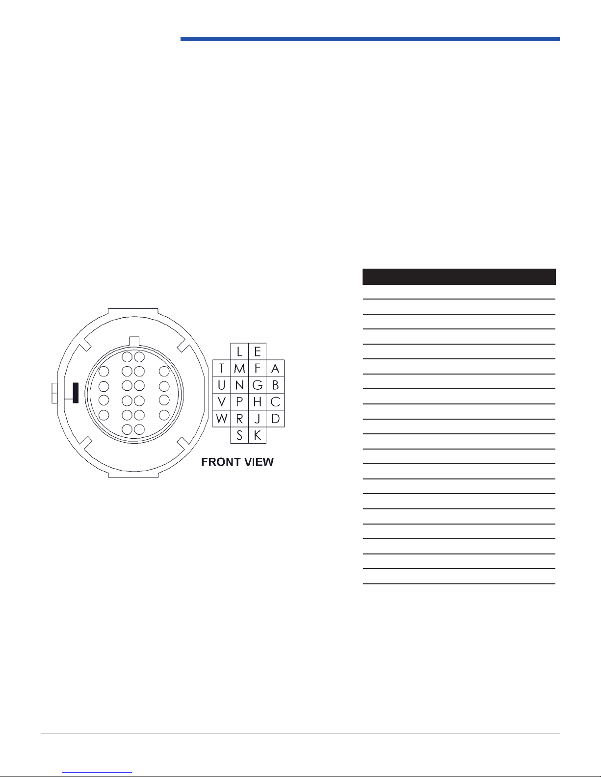
Pass-Thru Connector
The transmission to vehicle electrical interface is a 20 pin connector used to mate the internal and external harnesses of
the transmission. Use the alignment key to ensure proper installation. Reference Figure 1.5.2-1.
• The pass-thru connector envinromental temperature shall not exceed -40 to 135°C at any time. Proper shielding is
required. Reference Section 1.3.4 for temperature details.
Page 16
REV 1.1
10511 Old Ridge Rd. Ashland, VA 23005
Ph: 804.227.3023
Page 22
Powertrain Control Solutions
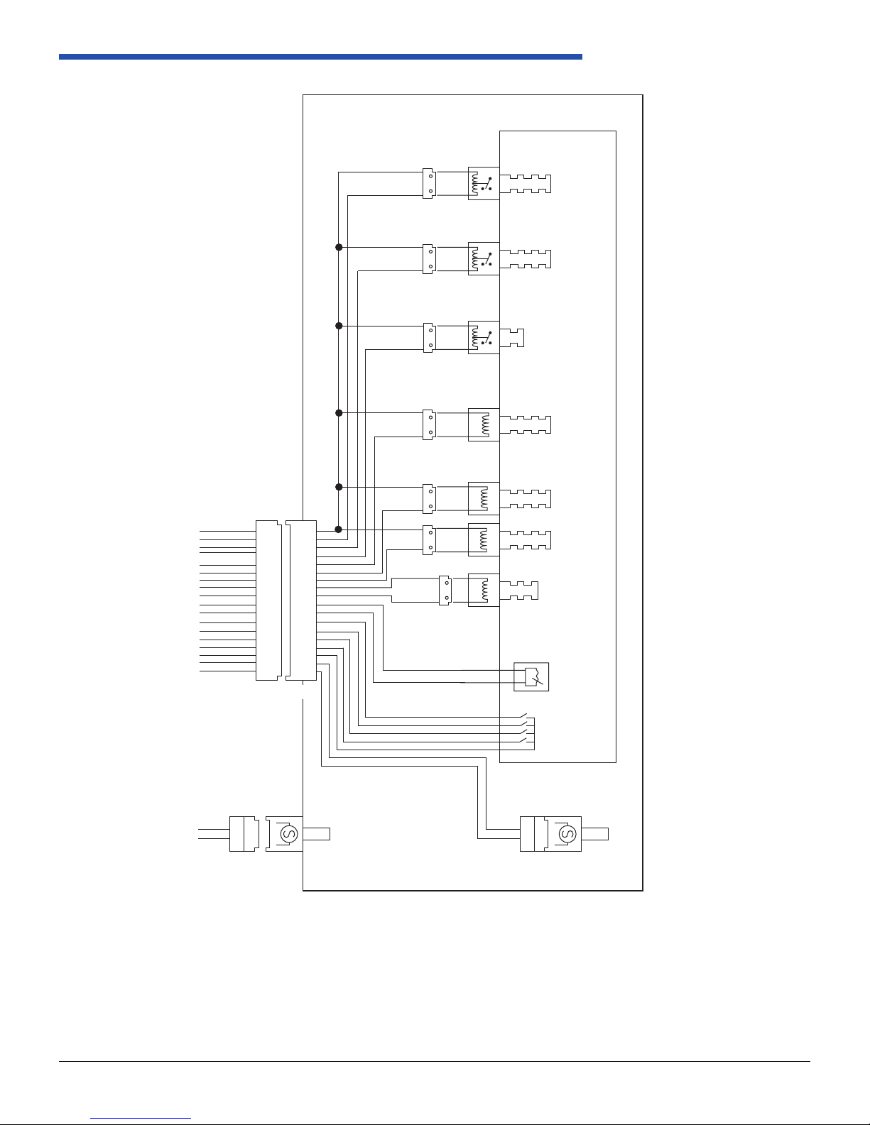
1.5.2 Internal Wiring
Unless otherwise specied, electrical components operating range shall be 8.0 to 18.0 VDC. It is recommended that
the transmission controls solenoids are not engaged without the engine running. Transmission electrical components
should be fused separately from other vehicle components.
Electrical Connections
Two connections must be made to the transmission to interface with the TCM. The connections are for the transmission
control connector and the output speed sensor. Figures 1.5.2-1 and 1.5.2-2 shows the internal system schematic.
CAV Function
A Shift SOL ‘A’
B Shift SOL ‘B’
C Line Pressure +
D Line Pressure -
E Switched +12V
F IMS A
G IMS C
H IMS B
J IMS P
K Turbine Speed +
L Trans Temp Sensor
M Trans Temp Sensor Ground
N IMS Ground
P
TCM Connector
R Forward Clutch SOL
S Reverse Clutch SOL
T TCC SOL
U TCC PWM
V Turbine Speed
W Neutral Safety
Page 17
Figure 1.5.2-1: TCM Connector and Terminal Locations
REV 1.1
10511 Old Ridge Rd. Ashland, VA 23005
Ph: 804.227.3023
Page 23
TRANSMISSION
VALVE BODY
SHIFT
SOLENOID A
SHIFT
SOLENOID B
TCC ENABLE
SOLENOID
(ON/OFF)
TCC CONTROL
PWM SOLENOID
4LHD/4LHDX Application Manual
VEHICLE
CONNECTOR
FORWARD
CLUTCH
SOLENOID
E
A
B
T
D
M
G
H
J
N
K
V
E
A
B
T
U UU
R
S
C
D
L
M
F
G
H
S1
S2
A
B
E
A
B
T
RR
SS
CC
D
LL
M
FF
G
H
J
J
N
N
K
K
V
V
PRESSURE
CONTROL
SOLENOID
P1
‰
‰
OUTPUT
SPEED
SENSOR
TURBINE
SPEED
SENSOR
➤
A
C
B
P
Internal
Mode
Switch
REVERSE
CLUTCH
SOLENOID
TEMP
SENSOR
‰
‰
Page 18
Figure 1.5.2-2: Transmission Electrical Schematic
REV 1.1
10511 Old Ridge Rd. Ashland, VA 23005
Ph: 804.227.3023
Page 24

SECTION 2
TRANSMISSION TO VEHICLE
INTERFACES
Page 25

Powertrain Control Solutions
Section 2 Transmission to Vehicle Interfaces
2.1 Transmission Input
2.1.1 Torque Converters
Power input and torque multiplication are accomplished by the transmission torque converter. Converters are
available with a variety of internal components that offer torque ratios up to 1.95 to 2.1 (Refer to Section 2.2.4).
A spring damper smooths out torsional variation when the converter clutch is locked. The correct choice of
components will result in a package that provides an optimum level of fuel economy, performance, and driveability.
We offer two torque converters, 258mm and 300mm. The 258mm torque converter is used in SAE4/SAE5
applications while the 300mm torque converter is used in SAE3 and GM 3.0L/4.3L applications.
Common Name K Factor ST/Ratio
258 146 1.95
300 114 2.1
300mm is used with SAE3, GM
3.0L & 4.3L applications
258mm is used with SAE4/SAE5
applications
Figure 2.1-1: Torque Converters
Page 19
REV 1.1
10511 Old Ridge Rd. Ashland, VA 23005
Ph: 804.227.3023
Page 26

Powertrain Control Solutions
4.2.4. Flexplate to Converter Connection
Converter piloting is provided by a counterbore in the end of the engine crankshaft, shown
in Figure 4.2.4-1. Axial movement of the converter is contained within this “floating pilot” to
ensure that thrust loads are not transferred to the crankshaft thrust bearing. Grease should
be applied to the pilot or bore to act as a lubricant and corrosion inhibitor. Care must be
taken to ensure that the converter pilot is seated properly in its bore.
During assembly to the engine, the transmission must be supported so that it is
horizontal, or with the bell housing slightly elevated. This will prevent the torque
converter from slipping out of engagement with the oil pump
shaft when the shipping
bracket is removed. The transmission case face must be squarely seated against the
engine face, with locating dowels fully engaged, before its attaching bolts are tightened.
After the case attachment is made, the converter must be moved to bring its lug surface
into contact with the flexplate (and to bring the pilot diameter into the crankshaft bore).
All bolts must be hand started to prevent cross threading. Moving the converter into
place before tightening its attaching bolts ensures that both the transmission to engine
and the converter to flexplate have been properly aligned and that the converter is free to
move in the crankshaft bore without loading the crankshaft bearings. The transmission to
engine attachment, and the converter to flexplate must NOT be drawn into position with
only one bolt tightened with a power gun.
The flexplate must be indexed for alignment to the converter attachment lugs. Access for
indexing the flexplate ring gear is available on some of the transmission case bell
housings adjacent to the starter pocket. In other cases, there is no access provision and
the flexplate is indexed via the engine crankshaft pulley.
A paint spot is applied to the front edge of the torque converter to indicate the lowest
mass location as measured during the converter balancing operation at the
manufacturing plant. The spot may be used to line up with any identified heavy spot on
the flexplate during assembly to the engine.
The following figures illustrates the converter bolt patterns and thread sizes. The choice
of bolt must consider factors such as thread engagement and clearances at the bolt head
and thread end. The threaded end must not bottom out against the converter cover. A
thread adhesive should be used to ensure durability.
Converter piloting is provided by a counter bore in the end of the engine crankshaft or ywheel adapter, shown in
Figure 2.1.1-2. Axial movement of the converter is contained within this “oating pilot” to ensure that thrust loads are
not transferred to the crankshaft thrust bearing. Grease should be applied to the pilot or bore to act as a lubricant and
corrosion inhibitor. Care must be taken to ensure that the converter pilot is seated properly in the engine crankshaft or
ywheel adapter bore.
During assembly to the engine, the transmission must be supported so that it is horizontal, or with the bell housing slightly
elevated. This will prevent the torque converter from slipping out of engagement with the oil pump shaft when the shipping
bracket is removed. The bellhousing face must be squarely seated against the engine face, with locating features fully
engaged, before its attaching bolts are tightened.
After the bellhousing attachment is made, check the converter pullout (Reference 2.1.3) and then move its lug surface
into contact with the explate (and to bring the pilot diameter into the crankshaft bore). All bolts must be hand started
to prevent cross threading. Moving the converter into place before tightening its attaching bolts ensures that both the
transmission to engine and the converter to explate have been properly aligned and that the converter is free to move in
the crankshaft bore without loading the crankshaft bearings. The transmission to engine attachment, and the converter to
explate must NOT be drawn into position with only one bolt tightened with a power gun.
The explate must be indexed for alignment to the converter attachment lugs. Access for indexing the explate ring gear
is available on some of the transmission bell housings adjacent to the starter pocket. In other cases, there is no access
provision and the explate is indexed via the engine crankshaft pulley.
A paint spot is applied to the front edge of the torque converter to indicate the lowest mass location as measured during
the converter balancing operation at the manufacturing plant. The spot may be used to line up with any identied heavy
spot on the explate during assembly to the engine.
The following gures illustrates the converter bolt patterns and thread sizes. The choice of bolt must consider factors such
as thread engagement and clearances at the bolt head and thread end. The threaded end must not bottom out against
the converter cover. A thread adhesive should be used to ensure durability.
➤
FLEXPLATE
END OF
ENGINE
CRANKSHAFT
➤
Page 20
➤
Figure 2.1.1-2: Torque Converter Pilot Arrangement
REV 1.1
TORQUE CONVERTER HUB
(CONVERTER PILOTING)
Ph: 804.227.3023
10511 Old Ridge Rd. Ashland, VA 23005
Page 27

4LHD/4LHDX Application Manual
Bellhousing Converter A B
GM LS
PCS SAE3 & SAE4
258 mm 36.7 mm (1.446”) 25.7 mm (1.012”)
300 mm 21.7 mm (0.854”) 10.7 mm (0.421”)
258 mm 49.4 mm (1.944”) 38.4 mm (1.512”)
300 mm 34.4 mm (1.354”) 23.4 mm (0.921”)
Dimension A: Rear face of engine to torque converter mounting lug.
Dimension B: Rear face of engine to explate.
The explate shown above is PCS part number TRN7007, reference Section 2.1.2 in this document or the PCS OEM
Parts Catalog for more information.
The dimensions provided indicate the installed depth of the torque converter. The tolerance is +/- 0.062”.
Every installation must have the converter pull-out measured and veried before the vehicle is operated. Improper torque
converter pull-out will result in transmission malfunction and/or damage.
To measure the Torque Converter Pull-Out:
1. Align and install the bellhousing/transmission assembly to the engine. Before tightening the bellhousing fasteners
completely, check to be sure converter rotates freely.
2. Once the bellhousing fasteners are torqued to specication, push the torque converter back into the transmission as
far as possible.
3. Using feeler gauges or calipers measure the gap between the explate mounting surface and the torque converter
mounting pads. If the gap distance is between .060” (1.5mm) and .187” (4.7mm) it is OK to bolt up the torque converter.
Reference Section 2.1.3 for a more detailed description of this verication process.
Page 21
REV 1.1
10511 Old Ridge Rd. Ashland, VA 23005
Ph: 804.227.3023
Page 28

Powertrain Control Solutions
258 mm CONVERTER LUG TO REAR FACE OF ENGINE
22.09mm ± 0.83
(ENGINE OFF)
SECTION A - A
➤
➤
ENGINE
BLOCK
300 mm CONVERTER LUG TO REAR FACE OF ENGINE
21.667mm±1.181
(ENGINE OFF)
3 HOLES
SECTION A - A
➤
➤
ENGINE
BLOCK
CONVERTER
PILOT
Ø43.234±
A
➤
➤
A
➤
➤
.016
.015
mm
➤
Figure 2.1.1-4 300 mm Torque Converter Attachment Features
281.0mm
➤
M10 x 1.5-6H THD THRU
CONVERTER
PILOT
Ø20.94 ± 0.02mm
A
➤
➤
A
➤
➤
Page 22
Ø 247.65mm
➤
➤
M10 x 1.5 - 6H THD THRU LUG
3 HOLES
Figure 2.1.1-5: 258 mm Torque Converter Attachment Features
REV 1.1
10511 Old Ridge Rd. Ashland, VA 23005
Ph: 804.227.3023
Page 29

4LHD/4LHDX Application Manual
Figure 2.1.1-6: C6 Torque Converter Attachment Features
Page 23
REV 1.1
10511 Old Ridge Rd. Ashland, VA 23005
Ph: 804.227.3023
Page 30

Powertrain Control Solutions
2.1.2 Flexplate
PCS uses a universal explate for our GM and SAE applications, while the C6 converter is designed for the stock C6
explate.
Page 24
Figure 2.1.2-1 GM Flexplate
Figure 2.1.2-2 C6 Flexplate
REV 1.1
10511 Old Ridge Rd. Ashland, VA 23005
Ph: 804.227.3023
Page 31

4LHD/4LHDX Application Manual
2.1.3 Flywheel Interface
Having the torque converter correctly spaced with the transmission pump is critical for optimal functionality and to prevent
permanent damage during installation/operation. To adapt to a wide variety of ywheels and bellhousing combinations,
PCS uses Flywheel Kits (a combination of Engine Spacers and Flywheel Adapters as shown in Figure 2.1.1-3) to mate
the 4LHD/4LHDX explate/torque converter with the engine’s ywheel. These parts must not be swapped between
different Flywheel Kits. After installation of the Flywheel Kit/explate to the engine and then installation of the transmission/
bellhousing to the engine, it is necessary to verify the “Torque Converter Pull Out” which can be measured by the distance
between the torque converter pad and the explate, referenced in Figure 2.1.1-3. This measurement only works if the
torque converter has been gently pushed into the transmission pump as far as possible, which should already be the case
for proper installation referenced in section 3.1.3. If the torque converter is removed from the transmission/pump for any
reason, reinsertion of the torque convert must be done gently and precisely. There are two tabs in the transmission pump
assembly, which must be correctly aligned and integrated with the corresponding slots on the torque converter pilot. If
this is not done properly, permanent damage to the transmission will result when the engine/transmission are assembled.
Reference the PCS OEM Parts Catalog for a current list of engine and ywheel applications, and PCS engineering for
new ones.
Flexplate
Engine Spacer
Flywheel Adapter
Figure 2.1.3-1 Example Flywheel Kit
Note: The explate kit is not included in the ywheel kit.
Page 25
REV 1.1
10511 Old Ridge Rd. Ashland, VA 23005
Ph: 804.227.3023
Page 32

Powertrain Control Solutions
2.1.4 Bellhousing to Flywheel Housing Interface
The conguration of the engine mounting face varies according to engine usage. The 4LHD/4LHDX currently supports
ve types of mounting faces. Contact PCS for an updated list. Figures 2.1.4-1 to 2.1.4-5 show these bellhousing
congurations. Dimensions are for reference only.
Reference section 3.1 for a discussion of assembly considerations that are critical to the alignment of the transmission
to the engine. These bellhousings have been factory installed to 51 lb*ft / 70 N*m, removing them without the instruction/
permission of PCS will damage the transmission and void your warranty.
Page 26
Figure 2.1.4-1: GM GEN III Bellhousing Front View
REV 1.1
10511 Old Ridge Rd. Ashland, VA 23005
Ph: 804.227.3023
Page 33

4LHD/4LHDX Application Manual
Page 27
Figure 2.1.4-2: PCS SAE3 Bellhousing Front View
REV 1.1
10511 Old Ridge Rd. Ashland, VA 23005
Ph: 804.227.3023
Page 34

Powertrain Control Solutions
Page 28
Figure 2.1.4-3: PCS SAE4 Bellhousing Front View
REV 1.1
10511 Old Ridge Rd. Ashland, VA 23005
Ph: 804.227.3023
Page 35

4LHD/4LHDX Application Manual
Figure 2.1.4-4 PCS SAE5 Bellhousing Adapter Front View
Page 29
REV 1.1
10511 Old Ridge Rd. Ashland, VA 23005
Ph: 804.227.3023
Page 36

Powertrain Control Solutions
Page 30
Figure 2.1.4-5: PCS C6 Bellhousing Front View
REV 1.1
10511 Old Ridge Rd. Ashland, VA 23005
Ph: 804.227.3023
Page 37

2.2 Transmission Output
2.2.1 Lubrication and Sealing
Referenced in Figure 2.2.1-1 is the lubrication system for all 4LHD/4LHDX extension housings. This system
ensures the spline engagement, rear bearings, and seals retain optimal functionality for the life of the transmission.
It is critical that the extension housing is properly sealed from the environment and transfer case oil. Fluid enters
the cavity from both the oil jet and output shaft bearing, and drains to the oil pan through the return vent. PCS uses
a universal extension housing to transmission seal. The seal between the transmission case and the extension
housing is referenced in Figure 2.2.3-4. During transmission operation the return vent must not be plugged, as
this will cause the extension housing to ll with uid which can cause permanent damage. Contact PCS in the
case of applications requiring dry extension housings.
4LHD/4LHDX Application Manual
Page 31
Figure 2.2.1-1: Extension Housing Fluid Control
2.2.2 Output Shaft Requirements
Propshaft Alignment and Torsional Vibrations
The presence of universal joints in the propshaft will induce torsional vibrations in the driveline, due to the angles
at which the driveshafts operate. This can have a detrimental effect on component durability.
The chassis shall be designed to minimize the torsional vibration resulting from excessive driveshaft angle. Refer
to SAE Design Guideline AE-7: Universal Joint and Driveshaft Design. Excitations in the driveline, during any
continuously operating condition, shall not exceed:
Torsional excitation: 400 rad/s2
Inertia excitation: 1000 rad/s2
If a design approaches or exceeds these criteria, or if a design is considered at risk, a test shall be conducted to
ensure that the transmission is not compromised. This information can be found in the SAE Design Guide Line
AE-7: Universal Driveshaft Design.
REV 1.1
10511 Old Ridge Rd. Ashland, VA 23005
Ph: 804.227.3023
Page 38

Powertrain Control Solutions
Noise and Vibration
Special attention should be given to the following areas when developing a vehicle mounting system. Attachments to
these areas where the noise is generated will result in a direct noise path and could ultimately result in noise quality
concerns. In addition, mounts should not have the same excitation frequency at or near the natural vibrations of the
following components:
• Gears
• Bearings
• Converter
• Oil pump
2.2.3 Extension Housings
Typical vehicle mounting applications are shown in Figures 2.2.3-1 to 2.2.3-10. All four standard extension housings
available through PCS have integrated vehicle mounts. Any proposed boss locations and threaded fastener designs
must have PCS Engineering approval for load analysis. Mount loads should be supplied by the customer. For an updated
list of vehicle mount options reference the PCS OEM Parts Catalog. The factory torque rating for the six transmission to
extension housing bolts is 37 ft*lbs / 45 N*m. In addition, the speed sensor bolt in 2WD applications has a torque rating
of 8 lb*ft / 11 N*m.
A proper installation supports the transmission weight but must also:
• Avoid loading the internal components
• Allow for frame twist
• Absorb driveline torque
• To damp driveline shock forces
• Not exceed 200 lbs on transmission mount
GM 2WD Extension Housing
Used in rear wheel drive applications, this extension housing does not have a parking brake incorporated. When installed
properly the journal of the slip yoke provides a seal for the rear of the transmission. This is critical due to the lubrication
jet and return vent on the rear face of the 4LDH/4LHDX. The slip yoke features referenced in the table below are
required to ensure proper functionality and durability of the driveline system with respect to the transmission interface
subcomponents i.e., bushing and seal. There are many options available through Spicer and other manufacturers, as
each vehicle has different driveline lengths and power ratings. A common example is the Spicer 2-3-12411X from their
Slip Yoke Assemblies Catalog. Reference Figure 2.2.3-1 for transmission output interface.
Slip Yoke Details
Spline Type 27 Tooth (Involute)
Journal Diameter 38.176 - 38.151 mm (1.503 - 1.502 in)
Journal Surface Finish 0.25 - 0.50 μm (10 - 20 μin) Ra
NOTE: For the nishing procedure, Residual burrs produced by the turning, grinding and polishing operations to the slip yoke journal must be of a
favorable i.e., non-aggressive direction of lay to the journal rotational direction when the vehicle is in forward drive.
Page 32
REV 1.1
10511 Old Ridge Rd. Ashland, VA 23005
Ph: 804.227.3023
Page 39

4LHD/4LHDX Application Manual
2WD SPLINE DATA
Number of Teeth 27 Form Diameter 27.94 mm
Module 1.0583 mm Min Effective Tooth Thickness (Reference) 1.732 mm
Diameter Pitch 24.000 mm Max Effective Tooth Thickness 1.821 mm
Pressure Angle 30.0˚
Pitch Diameter
(Reference)
Base Diameter
(Reference)
28.575 mm
24.747 mm Measure Over Pins
Major Diameter 29.822-39.845 mm
Minor Diameter 27.00-27.20 mm Spline Length 115.5 mm
Min Actual Tooth
Thickness
Max Actual Tooth
Thickness
Pin Diameter
(Reference)
1.719 mm
1.795 mm
Min: 31.173 mm
Max: 31.051 mm
1.778 mm
SIDE VIEW
BOTTOM VIEW
SIDE VIEW
Page 33
Figure 2.2.3-1: GM 2WD Extension Housing
REV 1.1
10511 Old Ridge Rd. Ashland, VA 23005
Ph: 804.227.3023
Page 40

Powertrain Control Solutions
GM 4WD Extension Housing
Shown in Figures 2.2.3-2 and 2.2.3-3 is the PCS approved two speed electronic shifting transfer case. 2Hi, 4Hi, Neutral,
and 4Lo are controlled via an external PCS Transfer Case Module. The rear output shaft takes a GM 32 tooth female yoke,
while the front output shaft takes a GM 32 tooth make yoke. Reference the PCS OEM Parts Catalog for part numbers.
Page 34
Figure 2.2.3-2: GM 4WD Extension Housing
REV 1.1
10511 Old Ridge Rd. Ashland, VA 23005
Ph: 804.227.3023
Page 41

4LHD/4LHDX Application Manual
Page 35
Figure 2.2.3-3: GM 4WD Transfer Case
REV 1.1
10511 Old Ridge Rd. Ashland, VA 23005
Ph: 804.227.3023
Page 42

Powertrain Control Solutions
PCS Parking Brake
The PCS parking brake is a disk style brake that attaches to the 4LHD/4LHDX in rear wheel drive applications. It provides
a mechanical brake and also has an optional hydraulic brake that can be used for certain applications. It also can be
electronically controlled with the Parking Brake Module.
The caliper can be mounted in several different clocking orientations and is available with a left hand cable exit or a right
hand cable exit.
BOTTOM VIEW
Figure 2.2.3-4: PCS Parking Brake Explosion View
SIDE VIEW
Figure 2.2.3-5: PCS Parking Brake Dimensions
Page 36
REV 1.1
10511 Old Ridge Rd. Ashland, VA 23005
Ph: 804.227.3023
Page 43

4LHD/4LHDX Application Manual
Figure 2.2.3-6: PCS Parking Brake Feature Locations
The PCS Parking Brake is designed and manufactured to take a standard driveshaft ange yoke, dimensions shown in
Figure 2.2.3-8. A common example, shown in gure 2.2.3-7 is the Spicer 3-2-159. This is a parking brake only, not an
emergency brake. Max vehicle holding weight is dependant on nal gear ratio and tire size. Contact PCS for application
engineering.
BORE FOR
MALE FLANGE
Figure 2.2.3-7 Example Flange
Page 37
REV 1.1
Figure 2.2.3-8 Flange Yoke Bolt Circle
Ph: 804.227.3023
10511 Old Ridge Rd. Ashland, VA 23005
Page 44

Powertrain Control Solutions
PCS C6 Extension Housing
This replacement package holds all the same specications as the old Ford C6 w/ drum parking brake option. Shown in
Figures 2.2.3-9 to 2.2.3-10. This utilizes the original brake housing, drum, driveshaft yoke, and other hardware to correctly
seal and operate. Same as the original, our output shaft is an SAE10B spline. Reference SAE Standard J499 for full
spline detail.
Figure 2.2.3-9: PCS 4LHD/4LHDX with C6 Bellhousing and C6 Output
Page 38
REV 1.1
10511 Old Ridge Rd. Ashland, VA 23005
Ph: 804.227.3023
Page 45

4LHD/4LHDX Application Manual
Page 39
Figure 2.2.3-10: PCS C6 Extension Housing
REV 1.1
10511 Old Ridge Rd. Ashland, VA 23005
Ph: 804.227.3023
Page 46

Powertrain Control Solutions
2.3 Transmission Cooling
Transmission uid is heated primarily by the pumping action that occurs within the torque converter. Heat load varies,
depending on speed, grade, duty cycle, ambient temperature, etc. A method of heat dissipation must be provided in order
to maintain proper transmission temperature.
Cooling is accomplished by circulating the uid through a cooler that is external to the transmission. Incorporation of the
cooler within the radiator is recommended since this provides the added advantage of quick warm-up of the transmission
in cold climates. If the cooler is located in a radiator end tank, the inlet pipe should be at the lowest point of the cooler.
If an auxiliary cooler is used, it should be located in the return line to the transmission, and the system should incorporate
a bypass to allow lubrication ow under very low ambient temperature conditions. Adequate ow shall be veried by test.
NOTE: It is recommended for the transmission
cooler to ow IN at the cooler bottom port and
OUT at the cooler top port. This is recommended
not only so that heavy particles and sediment fall
to the bottom of the cooler instead of returning
to the transmission sump, but also allows any
trapped air in the system to rise and leave the
heat exchanger via the upper outlet tting.
2.3.1 Cooling System Overview
Automatic Transmission Fluid
Automatic transmission uid (ATF) is a complex lubricant that consists of a base oil and an additive package.
The additive package is designed to impart several desirable performance characteristics, above and beyond
those that the base oil could do alone. The performance of ATF’s are driven by the needs of the product and must
provide excellent uidity values for both low and high temperature transmission performance. Fill tubes, ll caps
and bottom pans should be accessible for repair without removing the transmission from the vehicle. In addition,
external seals should be accessible for serviceability.
Fluid Specication
The ATF to be used in any PCS 4LHD/4LHDX shall be Dexron® VI or equivalent. Transmission damage caused
by the use of improper uid will not be covered under warranty.
Page 40
Figure 2.3-1 Cooler System
REV 1.1
10511 Old Ridge Rd. Ashland, VA 23005
Ph: 804.227.3023
Page 47

4LHD/4LHDX Application Manual
3.2.1. Cooling
Transmission fluid is heated primarily by the pumping action that occurs within the torque
converter. Heat load varies, depending on speed, grade, duty cycle, ambient
temperature, etc. A method of heat dissipation must be provided in order to maintain
proper transmission temperature.
Cooling is accomplished by circulating the fluid through a cooler that is external to the
transmission. Incorporation of the cooler within the radiator is recommended since this
provides the added advantage of quick warm-up of the transmission in cold climates. If
the cooler is located in a radiator end tank, the inlet pipe should be at the lowest point of
the cooler.
If an auxiliary cooler is used, it should be located in the return line to the transmission,
and the system should incorporate a bypass to allow lubrication flow under very low
ambient temperature conditions. Adequate flow shall be verified by test.
3.2.1.1. Cooler Line Connection
Cooler lines connect the transmission to the radiator (cooler). Refer to Figure 3.2.1.1-1
for the position of the “to cooler” and “from cooler” connections.
Cooler lines should be as short, and with as few bends as possible. The largest
feasible pipe bore should be used. Routing should avoid external heat sources (such
as exhaust pipes, catalytic converters etc.), protect the pipe from road hazards and
provide for ease of installation and removal. The cooler lines should be adequately
supported along their length to prevent vibrations from generating noise or fatigue
distress, and to prevent noise transmission into the vehicle structure. The cooler
circuits should be capable of withstanding 2068 kPa (300 psi) and fluid temperatures
of 177˚C (350˚F).
2.3.2 Cooler Requirements
To provide proper operation and longevity, the cooling system must maintain the transmission sump temperature below
132°C (270°F) and stator temperature below 177°C (350°F) at all times. This is dened as a “never exceed” limit under
all operating conditions. Average sump temperature must not exceed 110°C (230°F). The cooler must be capable of 4-5
kW of heat rejection for light duty applications, and 8-10 kW for heavy use such as industrial vehicles, off road equipment,
military and ground support equipment.
2.3.3 Cooler Lines
Cooler Line Connection: Cooler lines connect the transmission to the radiator (cooler). Cooler lines should be as short,
and with as few bends as possible. The largest feasible pipe bore should be used. Routing should avoid external heat
sources (such as exhaust pipes, catalytic converters etc.), protect the pipe from road hazards and provide for ease of
installation and removal. The cooler lines should be adequately supported along their length to prevent vibrations from
generating noise or fatigue distress, and to prevent noise transmission into the vehicle structure.
Flow Requirements: The transmission cooler lines and the oil cooler must ow a minimum of 6 LPM at 345 kPa (50 psi)
and 11 LPM at 690 kPa (100 psi). The ow test shall be run with 93˚C (200˚F) ATF.
Pressure Requirements: Cooler line pressure under normal operation will be between 200 kPa (30 psi) and 1,000 kPa
(150 psi). The transmission may produce pressure of up to 2,086 kPa (300 psi) at the cooler line entrance. This pressure
may be observed on start up or if there is blockage in the transmission cooling system (cooler lines, oil cooler, return tting
at transmission). The lines and ttings must all be rated for a minimum of 300 psi.
Temperature Requirements: The cooler lines, cooler, and ttings shall be capable of withstanding uid temperatures of
177˚C (350˚F).
FROM COOLER
TO COOLER
➤
Page 41
Figure 2.3.3-1 Cooler Line Connection
REV 1.1
➤
Ph: 804.227.3023
10511 Old Ridge Rd. Ashland, VA 23005
Page 48

Powertrain Control Solutions
The cooler line interface exiting the case of the 4LHD/4LHDX is a #6 SAE Dash Size ORB (O-Ring Boss) for the hydraulic
tting. Reference gure 2.3.3-2 for dimensions and SAE J514 for more detailed specications.
SAE J514 Dimensions
SAE Dash Size 6
Nom Tube OD (mm) 9.52
Nom Tube OD (in) 0.375
Straight Thread Size 9/16-18
Nom Pipe Size 1/8
Figure 2.3.3-2: Cooler Output Dimensions
Cooler Line Installation
The following two sections provide the general guidelines for cooler line installation.
I. Flare Type Fittings
1. Remove shipping plugs from cooler lines and ttings. Plugs should be removed as late as possible to avoid damage
or contamination of the cooler lines and ttings.
2. Loose assemble the lines to the transmission and hand start nuts. Torque as specied, 28 lb*ft / 38 N*m. Over torquing
could distress the established thread lock of the connector in the transmission case.
3. Assure hoses/pipes are not kinked, crossed, twisted or grounded to any unspecied vehicle components. Due care
must be taken to prevent intentional movement of the cooler lines in the assembly process. Unnecessary vibration,
leakage or transmission malfunction may occur.
II. Quick Connect Type Fittings
1. Remove shipping plugs from cooler lines and ttings. Plugs should be removed as late as possible to avoid damage
or contamination of the cooler lines and ttings.
2. While gripping pipe body below plastic cap, insert pipe into connector until a click is felt - DO NOT use cap to insert
pipe.
3. Ensure yellow identication band is entirely within quick connector assembly. If not, insert pipe until yellow is completely
hidden.
Page 42
REV 1.1
10511 Old Ridge Rd. Ashland, VA 23005
Ph: 804.227.3023
Page 49

4LHD/4LHDX Application Manual
4. Pull sharply on pipe to assure a correct connection.
5. Snap plastic cap onto quick connector assembly. Do not depress the retainer clip. There should be no gap between
the cap and the quick connector hex.
6. Ensure no pipe damage occurred during the process.
7. Assure hoses/pipes are not kinked, crossed, twisted or grounded to any unspecied vehicle components. Due care
must be taken to prevent intentional movement of the cooler lines in the assembly process. Unnecessary vibration,
leakage or transmission malfunction may occur.
2.3.4 Dipstick
Level setting must be done by means of a dipstick type indicator. The indication hardware is attached at the time of
assembly to the engine or vehicle. The conguration of the upper end of the ll tube is specic to each vehicle, according
to vehicle packing requirements.
Based on the OEM customer preference, if an
indicator stopper type is used, it is recommended
that the words “Trans Fluid” are plainly labeled for
customer identication.
The top of the ll tube must be arranged so that any
uid expelled from the ll under extreme adverse
conditions can not fall on surfaces hot enough (e.g.
exhaust system, turbo charger, etc.) to cause ignition
of the uid.
Powertrain Control Solutions Engineering will specify
nominal indicator marking positions. These will have
been derived from the transmission’s functional uid
level limits, which are different from the indicator
markings. The procedure to develop the indicator
markings from the functional level limits must take into
account the tolerance added by the indicator stick.
The 4LHD/4LHDX system depends on the tip of the
indicator contacting the indicator stop.
The system depends on the indicator being longer
than the nominal path thru the center of the ll tube.
The extra length is taken up as wind-up within the ll
tube. The amount of extra length is determined by
tube and indicator tolerances and length, and must
be such that it covers dimensional stack, but does not
load the indicator beyond the room available within
the ll tube path.
It is the customer’s responsibility to package and
source the proper indicator tube and indicator. PCS
has common dipsticks available. Reference the PCS
OEM Parts Catalog for more information.
Page 43
REV 1.1
Figure 2.3.4-1 Fluid Level Indication
Ph: 804.227.3023
10511 Old Ridge Rd. Ashland, VA 23005
Page 50

Powertrain Control Solutions
2.3.5 Overow Vent
During operation the transmission is subjected to heating and cooling. A breather tube is provided to prevent the inside
of the transmission from becoming pressurized. Refer to Section 1.1.2 or Figure 2.3.5-1 for location of the breather tube.
In the event that transmission uid is overlled, some uid may be expelled from the breather passage; therefore the
breather opening must not be directed at any hot components. The breather opening can be located remotely by attaching
a hose to the existing breather tube. The hose length and diameter shall be such that the pressure of the inside of
the transmission is always ±4.0 psi of atmospheric. A hose must not have any low spots that would allow any uid or
condensation to collect and prevent the free movement of air. The end of the hose shall be located at a position that does
not inhale environmental or vehicle contaminants.
Remotely attached breathers are required, new designs must be provided by the vehicle manufacturer to be reviewed
with Powertrain Control Solutions Engineering. PCS overow vent kits serve this purpose and are available for purchase.
Reference the PCS OEM Parts Catalog for part numbers.
Overow Vent Kit Installation
The following procedure should be applied when installing an overow vent kit. Improper installation could result in
transmission uid expelled from the hose and onto potential heat sources.
1. Apply lubricant to inner circumference of transmission vent hose. Secure hose 19 mm onto transmission vent tube.
2. Secure overow vent kit to local features on transmission or body. The uid relase vent should be routed toward rear
of transmission to avoid leakage onto transmission and vehicle components. The pressure release vent should be
moved towards the top of the bellhousing to prevent uid from accumulating in the hose.
3. The release vents referenced in Figure 2.3.5-1 must be directed away from potential heat sources, such as exhaust
or catalytic converter.
Page 44
Figure 2.3.5-1: Overow Vent Kit Attachment
REV 1.1
10511 Old Ridge Rd. Ashland, VA 23005
Ph: 804.227.3023
Page 51

4LHD/4LHDX Application Manual
2.3.6 Fluid Capacity
A universal bottom pan is provided with the PCS 4LHD/4LHDX. Approximate total uid capacity values are listed below.
Cooler size and cooler line lengths will alter these values.
• 8.4 L (8.8 qt) with 258 mm torque converter
• 10.8 L (11.4 qt) with 300 mm torque converter
2.3.7 Check Fluid Level
Proper uid level is vital to the operation of the transmission. An overll condition can be as detrimental as an under-ll.
With improper uid-level, uid may contact the rotating parts or the pump intake may become exposed, causing aeration,
possible overheating and erratic operation.
The transmission uid serves several functions, therefore it is imperative the uid supply be maintained appropriately. A ll
tube and dipstick must maintain the uid level above the pump suction port to prevent aeration of the oil. Aeration could
result in pump cavitation and erratic operation of the transmission. Aeration could also occur if the oil level is too high. The
uid could contact the rotating components within the transmission and result in erratic operation. In addition, overheating
or horsepower loss may occur. Fluid levels must be maintained within the recommended operating bands.
This procedure checks the transmission uid level, as well as the condition of the uid itself. Caution: Always use the
proper automatic transmission uid listed. Using incorrect automatic transmission uid may damage the vehicle.
Before checking the uid level, perform the following:
1. Start the engine and park the vehicle on a level surface. Keep the engine running.
2. Apply the parking brake and place the shift lever in PARK (P) or NEUTRAL(N).
3. Depress the brake pedal and move the shift lever through each gear range if available, pausing for about 3 seconds
in each range. Then, move the shift lever back to PARK (P) or NEUTRAL(N).
4. Allow the engine to idle 500–800 RPM for at least 1 minute. Slowly release the brake pedal.
5. Keep the engine running and observe the transmission uid temperature (TFT) using a scan tool or PCS software.
6. Using the TFT reading, determine and perform the appropriate check procedure. If the TFT reading is not within the
required temperature ranges, allow the vehicle to cool, or operate the vehicle until the appropriate TFT is reached.
Cold Check Procedure
Use the cold check procedure only as a reference to determine if the transmission has enough uid to be operated safely
until a hot check procedure can be made. The hot check procedure is the most accurate method to check the uid level.
Perform the hot check procedure at the rst opportunity. Use this cold check procedure to check uid level when the TFT
is between 27–32°C (80–90°F).
1. Start the engine and locate the transmission dipstick at the rear of the engine compartment, on the passenger’s side
of the vehicle.
2. Flip the handle up, and then pull out the dipstick and wipe the dipstick end with a clean rag or paper towel.
3. Install the dipstick by pushing it back in the dipstick tube all the way, wait three seconds and then pull it back out again.
Page 45
REV 1.1
10511 Old Ridge Rd. Ashland, VA 23005
Ph: 804.227.3023
Page 52

Powertrain Control Solutions
NOTE: Always check the uid level at least twice. Consistent readings are important to maintaining proper uid level. If
inconsistent readings are noted, inspect the transmission vent assembly to ensure it is clean and unclogged.
4. Keep the dipstick pointing down and check both sides of the dipstick, and read the lower level. Repeat the check
procedure to verify the reading. Reference Figure 2.3.7-1.
Figure 2.3.7-1 Cold Fluid Check
5. Inspect the color of the uid on the dipstick.
6. If the uid level is below the COLD check line, add only enough uid as necessary to bring the level
into the COLD line. It does not take much uid, generally less than one pint (0.5L). Do not overll.
7. If the uid level is in the acceptable range, push the dipstick back in all the way, then ip the handle down to
lock the dipstick in place.
8. Perform a hot check at the rst opportunity after the transmission reaches a normal operating temperature
between 82–93°C (180–200°F).
Hot Check Procedure
Use this procedure to check the transmission uid level when the TFT is between 82–93°C (180–200°F). The hot check
procedure is the most accurate method to check the uid level. The hot check should be performed at the rst opportunity
in order to verify the cold check. The uid level rises as uid temperature increases, so it is important to ensure the
transmission temperature is within range.
1. Start the engine and locate the transmission dipstick at the rear of the engine compartment, on the
passenger side of the vehicle.
2. Flip the handle up, and then pull out the dipstick and wipe the dipstick end with a clean rag or paper towel.
3. Install the dipstick by pushing it back in the dipstick tube all the way, wait three seconds and then pull it
back out.
NOTE: Always check the uid level at least twice. Consistent readings are important to maintaining proper uid level. If
inconsistent readings are noted, inspect the transmission vent assembly to ensure it is clean and unclogged.
4. Keep the dipstick tip pointing down and check both sides of the dipstick. Read the lower level. Repeat the
check procedure to verify the reading. Reference Figure 2.3.7-2.
Page 46
Figure 2.3.7-2 Hot Level Check
REV 1.1
10511 Old Ridge Rd. Ashland, VA 23005
Ph: 804.227.3023
Page 53

4LHD/4LHDX Application Manual
5. Inspect the color of the uid on the dipstick.
6. A safe operating uid level is within the HOT crosshatch band on the dipstick. If the uid level is not within the HOT
band, and the transmission temperature is between 82–93°C (180–200°F), add or drain uid as necessary to bring
the level into the HOT band. If the uid level is low, add only enough uid to bring the level into the HOT band.
NOTE: To assist in reaching the correct temperature range of 82–93°C (180–200°F), drive the vehicle in second gear
until the desired temperature is reached.
7. If the uid level is low, add only enough uid to bring the level into the HOT band. It does not take much uid,
generally less than one pint (0.5L). Do not overll. Also, if the uid level is low, inspect the transmission for leaks.
8. If the uid level is in the acceptable range, push the dipstick back into the dipstick tube all the way, and then ip the
handle down to lock the dipstick in place.
9. If applicable and if the vehicle is equipped, reset the transmission oil life monitor only if the uid was changed.
How to Add Fluid
Add uid only after checking the transmission uid while it is hot. (A cold check is used only as a reference.) If the uid
level is low, add only enough of the proper uid to bring the level up to the HOT area for a hot check. It doesn’t take much
uid, generally less than one pint (0.5 L). Don’t overll.
NOTICE: Use only uid labeled DEXRON® VI, because uid with that label is made especially for your automatic
transmission. Damage caused by uid other than DEXRON® VI is not covered by your transmission warranty.
• After adding uid, recheck the uid level as described under “How to Check”.
• When the correct uid level is obtained, push the dipstick back in all the way; then ip the handle down to lock the
dipstick in place.
Page 47
REV 1.1
10511 Old Ridge Rd. Ashland, VA 23005
Ph: 804.227.3023
Page 54

Powertrain Control Solutions
2.3.8 Fluid Change
The useful life of the transmission depends on the time at temperature of the ATF, which is a function of the transmission
duty cycle, cooling system efciency and local ambient temperatures. Transmission Fluid must be changed as listed
below.
Vehicle Class Normal Use
Commercial 1000 Hours or 12 Months (whichever comes rst)
NOTE: The transmission lter must be replaced at every uid change.
Removal Procedure
Disconnect the battery from the vehicle prior to performing this procedure.
WARNING: When the transmission is at operating temperatures, take necessary precautions when removing the
pan, to avoid being burned by draining uid.
1. Raise and support the vehicle.
NOTE: The uid can be reused after this procedure unless it smells burnt or is discolored. If a recovery system is
available, remove and store the uid. Remove the pan bolts and skip to step 6.
2. On some vehicles an exhaust heat shield may need to be removed to access the pan bolts. Remove this if
necessary.
3. Place a drain pan under the transmission oil pan.
4. Remove the oil pan bolts from the front and sides of the pan only.
Page 48
Figure 2.3.8-1
REV 1.1
10511 Old Ridge Rd. Ashland, VA 23005
Ph: 804.227.3023
Page 55

5. Loosen the rear oil pan bolts approximately 4 turns.
6. Lightly tap the oil pan with a rubber mallet in order to loosen
the pan to allow the uid to drain. Reference Figure 2.3.8-1.
7. Remove the remaining oil pan bolts. Reference Figure 2.3.8-2.
4LHD/4LHDX Application Manual
8. Remove the oil pan and gasket. Reference Figure 2.3.8-3.
Figure 2.3.8-2
Page 49
REV 1.1
Figure 2.3.8-3
Ph: 804.227.3023
10511 Old Ridge Rd. Ashland, VA 23005
Page 56

Powertrain Control Solutions
9. Grasp lter rmly while pulling down with a twisting
motion in order to remove the lter.
Reference Figure 2.3.8-4.
10. If the lter is going to be replaced, remove the lter seal. The
lter seal may be stuck in the pump; if necessary, carefully
use pliers or another suitable tool to remove the seal.
Reference Figure 2.3.8-5.
11. Discard the seal.
Figure 2.3.8-4
Page 50
REV 1.1
Figure 2.3.8-5
Ph: 804.227.3023
10511 Old Ridge Rd. Ashland, VA 23005
Page 57

1. Coat the new lter seal with automatic transmission
uid.
2. Install the new lter seal into the transmission case.
Tap the seal into place using a suitable size socket.
Reference Figure 2.3.8-6.
3. Install the new lter into the case.
4LHD/4LHDX Application Manual
4. Install the oil pan and a new gasket. Reference
Figure 2.3.8-7.
Figure 2.3.8-6
Page 51
REV 1.1
Figure 2.3.8-7
Ph: 804.227.3023
10511 Old Ridge Rd. Ashland, VA 23005
Page 58

Powertrain Control Solutions
5. Install the oil pan bolts and tighten alternately and evenly to
11 Nm (97 lb in). Reference Figure 2.3.8-8.
6. If previously removed, reinstall the exhaust heat shield.
7. Lower the vehicle.
8. Fill the transmission to the proper level with DEXRON® VI
transmission uid. Refer to Section 2.3.6 for uid capacity.
9. Check the COLD uid level reading for initial ll only.
10. Inspect the oil pan gasket for leaks.
11. Test drive vehicle and verify proper transmission operation.
12. Check uid level when transmission is at operating temperature.
Figure 2.3.8-8
Page 52
REV 1.1
10511 Old Ridge Rd. Ashland, VA 23005
Ph: 804.227.3023
Page 59

4LHD/4LHDX Application Manual
2.4 Transmission Shift Lever
Driver selection of the transmission range is normally accomplished through a cable linkage connecting a oor or column
mounted selection lever to a transmission shift lever on the manual shaft. The vehicle manufacturer must make provisions
to provide all the linkage and controls up to the transmission manual shaft. Sections 2.4.1-2.4.2 describe how to design
this linkage. For an electronic shift reference Section 2.4.3.
NSBU
NEUTRAL-START
BACKUP-SWITCH
(SOME APPLICATIONS)
TRANSMISSION
SHIFT LEVER
Figure 2.4-1 Typical Shift System
➤
➤
SHIFT CABLE
REACTION BRACKET
SHIFT CABLE MOUNTED
TO COLUMN OR FLOOR
RANGE SELECTION LEVER
➤
➤
➤
SHIFT CABLE
Page 53
Figure 2.4-2 Shift System with NSBU Switch
REV 1.1
10511 Old Ridge Rd. Ashland, VA 23005
Ph: 804.227.3023
Page 60

Powertrain Control Solutions
3.4.2. Manual Shaft/Lever Interface
The shift lever (which is to be supplied by the vehicle assembly division) must conform to
the following specification:
Stock Thickness: 4.3 to 4.7 mm (0.169 to 0.185 in)
Hardness: Surface file hard Rc 59 min.
Case depth 0.12 to 0.25 mm (0.005 to 0.010 in)
Parts should not be brittle.
Manual shaft connection:
The interface between the manual shaft flats and the lever flats must have a press fit of
0.00 to 0.13 mm (0.000 to 0.005 in).
Punch direction must be from the lead-in side.
Slot dimensions to be maintained for a minimum of 50% stock thickness from lead-in side.
No burrs permissible around slot on lead-in side.
Corrosion protection of external nut and lever required to be compatible with coating on
manual shaft.
2.4.1 Shaft Specs
The shift lever (which is to be supplied by the vehicle manufacturer) must conform to the following specication:
Stock Thickness: 4.3 to 4.7 mm (0.169 to 0.185 in)
Hardness: Surface le hard Rc 59 min.
Case depth 0.12 to 0.25 mm (0.005 to 0.010 in)
Parts should not be brittle.
Manual shaft connection:
The interface between the manual shaft ats and the lever ats must have a press t of
0.00 to 0.13 mm (0.000 to 0.005 in).
Punch direction must be from the lead-in side.
Slot dimensions to be maintained for a minimum of 50% stock thickness from lead-in side. No burrs permissible around
slot on lead-in side.
Corrosion protection of external nut and lever required to be compatible with coating on
manual shaft.
8.05 ± 0.13
M10 x 1.5-6g
8.40 ±
10.90 ± 0.04
12.677 ± 0.010
Page 54
0.03
0.02
Figure 2.4.1-1 Manual Shaft Dimension
REV 1.1
10511 Old Ridge Rd. Ashland, VA 23005
Ph: 804.227.3023
Page 61

4LHD/4LHDX Application Manual
3.4.1. Transmission Detent Angles
Angular positions of the nominal transmission range detents are shown in the following
figure.
2.4.2 Lever Specs
Angular positions of the nominal transmission range detents are shown in the following gure.
FLATS IN PARK
➤
➤
➤
8.405±0.025MM
1
➤
21.5°
➤
32.2°
43.4°
➤
10.7°
➤
➤
➤
➤
➤
P
➤
18.0°
R
➤
D
N
2
3
➤
➤
54.6°
➤
➤
Figure 2.4.2-1 Transmission Detent Angles
77.8°
Shift System Assembly Process
The shift lever must be retained on the manual shaft by a hand started nut tightened to 20 +/- 4 Nm (14.8 +/- 3 ft lb). The
tightening of the manual shaft nut to the transmission manual shaft must be performed with the shift lever and manual
shaft xtured to prevent rotation.
The adjustment of the shift cable or linkage must be performed with the selector system in its nal routed position,
the vehicle resting on its wheels, and the transmission in Neutral. This “adjusts out” positional tolerances between the
transmission and the shifter mechanism. After the cable or linkage is properly adjusted, the indicator may be installed and
adjusted. Adjustment of the indicator must also be completed in Neutral. The indicator adjustment must not precede the
shift cable or linkage adjustment.
Page 55
REV 1.1
10511 Old Ridge Rd. Ashland, VA 23005
Ph: 804.227.3023
Page 62

Powertrain Control Solutions
TORQUE
Transmission Range Selection System Requirements
System Drag: The maximum amount of drag associated with the shifter system as seen by the transmission must be
a minimum of 0.45 Nm (4.0 in lb) lower than the detent centering torque provided by the transmission. (See following
gure.) This will enable the transmission to control the position of the range selection system within each gear range.
Transmission Range Selection System Analysis
Driver selection lever effort is found by measuring the load at the end of the selection lever. The lever is moved from Park
to Low and Low to Park with the corresponding maximum load readings recorded.
System drag is evaluated by taking torque measurements at the manual shaft nut when rotating it through the ranges.
Measurements are recorded rst to determine total system torque with the shifter gate defeated and with the shift cable/
linkage system attached to the transmission shift lever. The transmission detent centering torque is then determined by
detaching the shift cable/linkage, removing the neutral start switch and again rotating the manual shaft nut. The system
drag, as seen by the transmission, is equal to the total system torque minus the detent centering torque. The detent
centering torque must be greater than the system drag. For shifter systems which contain a detent spring in the shifter,
total system torque is measured with the cable disconnected from the shifter. The shifter detent spring must provide
greater centering torque than the drag associated with the shifter and the indicator/close-out.
Typical sources of system drag include
• Cable friction
• Neutral start switch rotating torque
• Shifter pawl to gate plate
• Indicator slide effort
• Column to dashboard closeout
• Shifter closeout
R-NP-R N-D D-3 3-2 2-1 1-2 2-3 3-D D-N R-PN-R
Figure 2.4.2-2 System Drag vs. Transmission Centering Torque
Page 56
TRANSMISSION DETENT CENTERING TORQUE
MEASURED AT TRANSMISSION SELECTOR SHAFT
0.45 Nm DESIGN CONSTRAINT
RANGE SELECTION SYSTEM DRAG
MEASURED AT TRANSMISSION SELECTOR SHAFT
RANGE POSITION
REV 1.1
10511 Old Ridge Rd. Ashland, VA 23005
Ph: 804.227.3023
Page 63

4LHD/4LHDX Application Manual
3.4.4. Transmission Range Selection System Kinematic Relationship
Requirements
The transmission Park system is designed for park engagement with the
transmission detent roller located in the Park valley of the detent lever. The range
selection system must be designed to ensure that the roller is in the Park valley when
the range selection lever is in the minimum Park gate position.
Definitions
Minimum Park Gate: The operator lever position closest to Reverse that will allow
the shifter pawl to enter the park gate (Figure 3.4.4.1-1).
Transmission Range Selection System Kinematic Relationship
Requirements
The transmission Park system is designed for park engagement with the transmission detent roller located in the Park
valley of the detent lever. The range selection system must be designed to ensure that the roller is in the Park valley when
the range selection lever is in the minimum Park gate position.
Denitions
Minimum Park Gate: The operator lever position closest to Reverse that will allow the shifter pawl to enter the park gate
Reference Figure 2.4.2-3.
SELECTOR IN MINIMUM
PARK GATE POSITION
PARK GATE
N
R
PAWL
Lost System Motion: The difference between range selection lever movement and transmission detent lever movement.
Lost system motion consists of system lash and component deection.
Figure 2.4.2-3 Minimum Park Gate Position
Page 57
REV 1.1
10511 Old Ridge Rd. Ashland, VA 23005
Ph: 804.227.3023
Page 64

Powertrain Control Solutions
3.4.4.2. Kinematic Requirements
Under minimum stack conditions and neglecting lost system motion, the kinematic
relationship between the detent lever and the range selection lever is to ensure that
the detent roller is in the Park valley when the range selection lever is in the minimum
Park gate as seen in the following figure.
The addition of lost system motion to the analysis will result in the detent roller being
initially positioned short of the Park valley at this point as seen in the following figure.
Spring forces from component deflection and the detent spring are to absorb the lost
system motion and position the detent roller in the Park valley.
ROLLER IN DETENT VALLEY
Kinematic Requirements
Under minimum stack conditions and neglecting lost system motion, the kinematic relationship between the detent lever
and the range selection lever is to ensure that the detent roller is in the Park valley when the range selection lever is in
the minimum Park gate as seen in the following gure.
SELECTOR IN MINIMUM
PARK GATE POSITION
DETENT SPRING LOCATED
IN VALLEY
Figure 2.4.2-4 Park Position Without Lost System Motion
The addition of lost system motion to the analysis will result in the detent roller being initially positioned short of the Park
valley at this point as seen in the following gure. Spring forces from component deection and the detent spring are to
absorb the lost system motion and position the detent roller in the Park valley.
SELECTOR IN MINIMUM
PARK GATE POSITION
SYSTEM INEFFICIENCY
P
N
R
Page 58
SPRING FORCE WILL ACT TO POSITON
Figure 2.4.2-5 Detent Position With Lost System Motion
REV 1.1
10511 Old Ridge Rd. Ashland, VA 23005
Ph: 804.227.3023
Page 65

4LHD/4LHDX Application Manual
2.4.3 Electronic Range
Use of a PCS valve body and PCS TCM can eliminate the shift cable. This allows for electronic shifting of the transmission
with the push of a button or movement of an electronic lever. In this application the transmission manual shaft must be
engaged in neutral at all times. Figure 2.3.4-1 represents one of many position switch options available. Reference the
PCS OEM Parts Catalog for other available options.
Page 59
Figure 2.4.3-1: Electronic Range Setup
REV 1.1
10511 Old Ridge Rd. Ashland, VA 23005
Ph: 804.227.3023
Page 66

Powertrain Control Solutions
Figure 2.4.3-2: Electronic Range Shifter
Shifter Specications
Column Size 38mm, 45mm, 55mm
Neutral Lock none, drop-down
Speeds 2, 3, 4, and 6
Lights -
Wiper Speeds -
Buttons Horn, Wash, Drop- Down
Connectors integral Packard, integral Deutsch, wire harness
Expected Life Cycle 1 million (rotary); 500000 (shifter handle)
Operating Temp Range -40°C - 85°C (-40°F - 185°F) 0% - 95% relative humidity
Operating Volt Range 3V - 32V
Solenoid Load 2A @ 12.8V with arc suppression
Measurements Ø 65.02 mm x 220.47mm L
(Ø 2.56 in x 8.68 in L)
Features IP67; turn signals are built to complement the shifter, or can be mounted as
stand alone
Shifter Pinout
Shifter Pin TCU Pin TCU Channel Description
1 * * *
2 7 Digital 6 Reverse
3 29 Digital 9 Gear Selection
4 ** ** **
5 * * *
6 10 Digital 8 Gear Selection
7 8 Digital 7 Forward
8 30 Digital 10 Optional Button
* N/A; Items are unterminated
** Signal Ground
Page 60
REV 1.1
10511 Old Ridge Rd. Ashland, VA 23005
Ph: 804.227.3023
Page 67

4LHD/4LHDX Application Manual
2.5 TCM Interface
The PCS 4LHD/4LHDX uses an electro-hydraulic control system to control shift pattern, line pressure, torque converter
clutch operation and transmission diagnostic actions. The electronic control system consists of inputs and outputs to the
control module. Inputs are dened as sensors and signals that monitor engine and transmission performance. Outputs
are signals to request the engine controller to modify engine torque during specic transmission shift and stall conditions.
It may also request increased idle speeds at elevated temperatures.
2.5.1 TCM Overview
TCM Handling
The following considerations should be adhered to when handling PCS transmission control module (TCM):
• Any TCM displaying visible damage shall not be installed in a vehicle.
• TCM enclosures shall not be opened by vehicle assembly personnel, and only on a case to case basis.
• Electrostatic discharge prevention techniques shall be employed by vehicle assembly personnel when handling
the TCM.
• PCS and the customer shall work together to dene the TCM programming.
• To properly install and uninstall the TCM2600 or TCM2800 connector, reference the MX123 Connection System
User Manual which can be found online. This is critical to prevent pin damage. For other TCMs, reference their
respective PCS TCM manuals.
TCM Installation
TCM mounting location denition, mounting bracket design, sourcing, validation, and vehicle assembly process
are all the responsibility of the customer.
If the vehicle will be subjected to electrical welding procedures (e.g. during body building assembly process) the
harness and TCM must be electrically isolated (removed) from the vehicle. Wire gage between the transmission,
TCM, and other vehicle systems shall comprehend the distances between components to minimize voltage
drop and signal degradation. The electrical supply for other electrical devices such as remote starters, alarm
systems, communication systems, etc. shall not interfere with the TCM voltage requirements. Reference the PCS
4LHD/4LHDX Technician’s Guide for more information.
Operating and Storage Temperature
Operating and storage temperature capabilities depend on control module design. PCS and the customer must
agree upon applicable TCM storage and operating temperature specications.
Generally, control modules may be stored between -40°C and 125°C.
Typical operating temperatures range from -40°C to 85°C for passenger compartment mounted TCMs and from
-40°C to 105°C for under the hood mounting locations.
The customer is responsible for meeting the agreed temperature limitations. PCS offers a bracket kit to mount the
TCM on the transmission case. Reference Figure 2.5.2-1 and the PCS OEM Parts Catalog for more information.
Page 61
REV 1.1
10511 Old Ridge Rd. Ashland, VA 23005
Ph: 804.227.3023
Page 68

Powertrain Control Solutions
Water/Dust Intrusion
PCS and the customer must agree upon applicable water and dust intrusion specications, test levels, and report formats.
More stringent requirements will increase TCM costs due to enclosure and connector sealing requirements.
Electromagnetic Compatibility (EMC)
PCS and the customer must agree upon applicable EMC specications, PCS shall be responsible for TCM testing to
applicable EMC specications. The customer shall be responsible for vehicle-level testing and certication.
Electronic Controller System Summary
Selecting an appropriate TCM solution requires several dening characteristics to be agreed between PCS and the
customer. Here is an example summary chart of plausible dening characteristic combinations:
Characteristic Example TCM
Mounting Location Transmisison
Operating Temperature -40°C to 105°C
Storage Temperature -40°C to 125°C
Water Intrusion Sealed to 3 foot submersion
EMC Specications GM 9100
Size and Weight H: 105 mm; W: 185 mm; D: 33 mm; Mass: 2000 gr.
Vehicle Electrical Interface SAE J1850/GM Class 2
Service Tool Interface SAE J1850/GM Class 2
Diagnostic Specications CARB OBDII
Control Algorithms
The TCM uses an electronic transmission control algorithm to monitor and control the transmission. This algorithm is
actually a combination of many algorithms.
Shift Point Control
PCS transmissions select proper operating gear based upon driver input, vehicle dynamics, engine operation, and vehicle
self-diagnostic operation. The TCM will operate the shift control solenoids to command the selected gear.
Shift Quality Control
PCS automatic transmissions provide smooth and precise ratio transitions between gears. During steady-state operation,
control algorithms optimize operation to increase vehicle fuel economy while protecting transmission durability. The TCM
will operate the line pressure control solenoid to ensure smooth ratio transitions and to maximize fuel economy.
Torque Converter Clutch Control
The Torque Converter Clutch is used to eliminate slip across the transmission torque converter. In some applications, a
continuously-slipping converter clutch may be available to improve vehicle performance. The TCM will operate the Torque
Converter Clutch solenoid(s) to maximize fuel economy and vehicle performance.
Abuse Protection
The automatic transmission control system will work to minimize torque disturbances shifts and to manage sudden torque
when abusive or excessive torque is being transmitted through the transmission. This interface is usually achieved by
software interfaces in TCM that will disable certain functions if they are determined abusive maneuvers.
Diagnostic System
PCS TCMs provide self-diagnostic testing to detect failures and degradation within the TCM and transmission hardware.
All PCS automatic transmissions will support the latest On-Board Diagnostic (OBD) legislation and J1939.
Page 62
REV 1.1
10511 Old Ridge Rd. Ashland, VA 23005
Ph: 804.227.3023
Page 69

4LHD/4LHDX Application Manual
2.5.2 Vehicle Electrical Interface and Diagnostics
TCM Connector(s)
TCMs will have one or more connectors depending upon:
1. Number of wires necessary for vehicle installation
2. Customer requirements for wiring harness design
3. TCM enclosure sealing
4. Wiring harness orientation
TCM Power Supply and Fusing
The TCM shall have an exclusive connection to vehicle battery power and switched ignition power.
The TCM shall not share electrical fusing with any other vehicle system.
The TCM typically assumes centralized load dump protection.
Vehicle/Service Tool Serial Data Interface
The TCM is accessed via a serial data interface and a laptop.
The Serial Data interface device is provided by PCS with each TCM.
Two typical vehicle service tool interfaces are:
• 2 X CAN 2.0b
• 1x RS-232, 1 x J1850
All PCS TCMs are based on the PCS proprietary real-time operating system which contains the functionality to control
nearly any automatic transmission with PCS controls and includes diagnostics.
The customer shall be responsible for service tool system testing and certication.
Diagnostic System Interface
When using TCMs, coordination of powertrain diagnostic system reporting becomes very important. PCS will work with
the customer to ensure the TCM meets applicable specications.
PCS shall be responsible for TCM unit testing to applicable diagnostic system specications. The customer shall be
responsible for vehicle-level certication.
Page 63
REV 1.1
10511 Old Ridge Rd. Ashland, VA 23005
Ph: 804.227.3023
Page 70

Powertrain Control Solutions
Electrical Inputs
Sensors monitor the engine and transmission parameters, and provide the inputs to the TCM. The following inputs are
external to the transmission and must be supplied to the TCM:
• Ignition voltage
• Brake status
• Engine speed
• Throttle position
• Serial data (diagnostics)
Discrete Inputs
CAN Communication: The PCS TCM can receive and transmit data over CAN. J1939 is supported as well as PCS
proprietary communication. Refer to the document PCS J1939 Messages for more information. If CAN is not available for
receiving inputs, refer to the discrete signal descriptions below.
Brake Switch: This line is either open or switches to ignition voltage or ground externally supplied to the switch. Under
normal conditions ignition voltage is present. This input can be set to be active high or active low.
Diagnostic Enable: The diagnostic request line enables the dashboard malfunction code feature. The single line is either
open or grounded. Due to the Fault detection hardware of the TCM output circuitry an incandescent bulb is require. LEDs
can potentially illuminate falsely.
Position (Transmission Range): The position indication is from three discrete inputs from an Internal Mode Switch
mounted inside the transmission on the shift lever.
The following external inputs are optional:
• Shift pattern select
• Engine coolant temperature
• Diagnostic enable
The following inputs are internal to the transmission:
• Position (transmission range)
• Input speed
• Transmission uid temperature
• Output speed
The inputs are either:
• Discrete
• Analog
• Discrete Frequency
• Bi-directional
Analog Inputs
Ignition Voltage: Ignition voltage is an analog input to the Control Module to determine ignition status. It should have an
operation range of 0 to 25.5 volts.
Throttle Position: The throttle position is an analog input requiring a three wire interface (reference voltage, signal and
ground) to a potentiometer.
Transmission Fluid Temperature: The transmission uid temperature is measured from a thermistor located in the
pressure switch manifold. It has an operating range from -40°C to 150°C (-40°F to 302°F).
Page 64
REV 1.1
10511 Old Ridge Rd. Ashland, VA 23005
Ph: 804.227.3023
Page 71

4LHD/4LHDX Application Manual
Discrete Frequency Inputs
Engine Speed: The engine speed is a frequency input provided by either a magnetic pickup or a conditioned signal
source. It requires a range of 300 to 7000 RPM. Signal output methods are developed with PCS and the engine supplier.
Output Speed: The output speed signal is a frequency input that is provided by a magnetic pickup or a conditioned signal
source. The magnetic pickup is a variable reluctance sensor that generates an AC sine wave induced by the 40 rotating
teeth of the target rotor. The sensor has a minimum output of 0.5 volts peak-to-peak, when loaded at 60 RPM (40 Hz) and
a maximum output of 200 volts peak-to-peak (loaded) at a speed of 7,200 RPM (4.8 kHz).
Bi-Directional Inputs
Serial Data (Diagnostics): The bi-directional data communication is used for diagnostics and service.
Page 65
Figure 2.5.2-1: PCS Example TCM
REV 1.1
10511 Old Ridge Rd. Ashland, VA 23005
Ph: 804.227.3023
Page 72

Powertrain Control Solutions
TCM2600 / TCM2800 Block Diagram
45
46
47
48
49
50
Input Power
19
18
20
9
42
2
3
4
5
6
7
8
10
29
30
31
32
33
34
35
36
Switched
+12V
Battery
Constant +12V
Ground
Ground
Input: 8-16 VDC
Digital Inputs
1
2
3
4
5
6
Programmable active high or low,
7
toggle or momentary
8
9
10
11
12
13
14
15
16
Analog Inputs (0-5V)
Battery
Voltage
Measurement
OBDII Diagnostics
PCS Tuning Interface
Data Logging Interface
PCS Proprietary
Transmission Controller
Embedded Operating
System v.4
PCS Core
TCM2600: v.6
TCM2800: v.7
CAN 2.0B
Configurable for J1939, GMLAN, and
PCS CAN
CAN1 H
CAN1 L
CAN2 H
CAN2 L
Programmable 120 Ohm terminating resistor
*
Comm
Serial: Use TCM4181 Cable
USB: Use TCM4180 Cable
J1850
Single Wire Diagnostic
PWM Outputs
1
2
*
Programmable
Bridge Mode
*
Measurement
Current
Ground
Programmable
Dither
3
4
TCM2600: Low Side Drive Only
TCM2800: Programmable High
or Low Side Drive
15
16
43
44
Tx
Rx
26
27
28
1
11
12
13
14
51
5
52
6
53
7
54
8
40
9
1
2
3
5V
4
Speed Inputs: TCM 2800
Programmable trigger lter
Speed Inputs: TCM 2600
Magnetic Sensor Interface
Programmable trigger lter
Hall-Eect Sensor Interface
5V
1k
5
1k
value and1k pull-up
value and1k pull-up
6
Speedometer Output
1
2
3
4
1
2
3
4
Circuit Board Temperature
Measurement
Figure 2.5.2-1: TCM Block Diagram
Digital Outputs
TCM2600: Low Side Drive Only
TCM2800: Programmable High
or Low Side Drive
Zero Crossing Output
Sensor Reference
Ground
Ground
Ground
4
5
6
5V
Rev 3 - 6/15
41
55
56
17
21
22
23
37
Page 66
REV 1.1
10511 Old Ridge Rd. Ashland, VA 23005
Ph: 804.227.3023
Page 73

4LHD/4LHDX Application Manual
2.5.3 Harness Overview
At PCS, we design and produce our harnesses using decades of automotive experience and customer feedback. We
have many standard 4LHD/4LHDX harnesses available, and we are eager to assist vehicle manufacturers in developing
vehicle specic units.
Wiring Harness Installation
When routing the wiring harness on the vehicle/transmission, avoid all high temperature heat sources in the engine
compartment. Assure the connection of all harnesses by using the “PUSH- CLICK-VERIFY” method. Avoid twisting of
the harness when securing the harness in clips. Secure the clips to transmission studs where appropriate. Insure that
the proper amperage fuses are used in the correct locations. Failure to do this will cause the transmission to have a
catastrophic failure. Refer to the PCS 4LHD/4LHDX Technician’s Guide for further instructions.
* No active connection necessary for vehicle operation. This connector is for troubleshooting/diagnostics through a PC connection.
Page 67
Figure 2.5.3-1: Example Harness
REV 1.1
10511 Old Ridge Rd. Ashland, VA 23005
Ph: 804.227.3023
Page 74

Powertrain Control Solutions
2.6 Throttle Position Sensor
The throttle position sensor is a critical input to the TCM. Failure to properly install the throttle position sensor will result in
improper transmission operation and damage. PCS can provide a throttle position kit as shown in Figure 2.6-1.
Figure 2.6-1 PCS TPS Overview
Position 1: LOW FAILURE POSITION. The sensor arm should return to this position when it is disconnected from the pedal or throttle
linkage. When the sensor is connected to the TCM the signal should measure less than 0.2V.
Position 2: IDLE POSITION. The sensor arm should be
off of the minimum stop such that the reported voltage is
between 0.5V and 1.5V.
POS 2 POS 3
Position 3: FULL THROTTLE POSITION. The sensor arm
should not contact the maximum stop. The reported voltage
POS 1
POS 4
in this position should be 3.5V to 4.5V.
Position 4: HIGH FAILURE POSITION. The maximum stop
position is designed to protect the sensor if a failure in the
linkage allows the sensor arm to extend past the normal
Minimum Stop
Maximum Stop
operating range.
Electrical Pinout
A +5V
B Ground
C Output Signal
Figure 2.6-2: TPS Postions
Page 68
REV 1.1
10511 Old Ridge Rd. Ashland, VA 23005
Ph: 804.227.3023
Page 75

4LHD/4LHDX Application Manual
TPS Verication Checklist
You must be able to answer YES to all of these statements to verify proper sensor installation.
1. The sensor is mounted in a location that is free from excessive vibration, protected from heat sources,
debris, and uids.
2. The sensor is mounted with proper fasteners (lock washers, lock nuts, etc) and uses appropriate
materials (no uncoated steel, etc) for the sensor to last the anticipated life of the vehicle.
3. When the accelerator pedal is at idle (not depressed), the sensor arm is off of the minimum stop and
the voltage as shown on the TCM software monitor screen is between 0.5V and 1.5V.
4. When the sensor arm is disconnected from the linkage that connects it to the engine or pedal, the
sensor arm returns to the minimum stop and the voltage on the TCM software monitor screen is below 0.2V. Code 22
becomes active after three seconds.
5. When the pedal is pressed, the sensor arm moves accordingly. There is no movement or “slop” such
that the pedal or engine throttle blade can move without seeing a voltage change on the TCM software monitor screen.
6. The sensor moves freely without binding. The sensor does not provide any resistance or change to
the operation of the throttle linkage.
7. When the accelerator pedal is at full throttle, the sensor arm does not contact the maximum stop and
the voltage as shown on the TCM software monitor screen is between 3.5V and 4.5V.
It is strongly recommended to use the arm provided by
PCS. In situations where the vehicle manufacturer must
design a custom arm, refer to gure 2.6.8.12-3 provided
for the design of the arm to the sensor.
Minimum length: 1.5” (so arm contacts stops)
Page 69
Figure 2.6-3: Shift Arm Specications
REV 1.1
10511 Old Ridge Rd. Ashland, VA 23005
Ph: 804.227.3023
Page 76

SECTION 3
PRODUCTION LINE PROCEDURES
Page 77

Powertrain Control Solutions
Section 3 Production Line Procedures
3.1 Assembly Procedures
3.1.1 Storage Requirements
The transmission shipping containers are designed to protect the transmission from some environmental conditions.
They are only effective if they are properly closed. Verify the top cover on the cocoons is properly aligned to
insure no foreign materials such as water can get inside. Transmissions should remain in shipping cocoons until
engine marriage. Transmissions should be stored in a dry, dust free environment at room temperature. Do not
store outside. Even if they are in the cocoons, there is still a risk for water and other foreign mater to get inside. If
water accumulates inside the cocoon, there are no drain holes for it to escape. The resulting condensation cycles
will insert water and debris into the transmission uid and cause permanent damage. Water damage will void all
warranties.
3.1.2 Handling Requirements
Transmissions should be assembled to vehicles in a timely manner to avoid contamination risks or damage
during the storage period.
Transmissions should be lifted from appropriate shipping racks by approved lifting hooks. The lifting hooks should
be designed to allow the following:
1. Lift the transmission by at least two lift points.
2. Employ one counter balance arm to ensure that the transmission is lifted straight up from the rack and it does
not swing or tilt.
3. Lift hook must include a safety latch to prevent the transmission from sliding off the hook during lifting.
4. The hooks utilized to lift and place the transmission parallel to the engine should position the transmission so
that the torque converter will line up with the ywheel and t squarely on the engine block alignment features.
The transmission should not be allowed to tip forward. The torque converter may be disengaged from the
transmission causing injury or damage, or it may move away from the transmission bell housing far enough to
disengage from the oil pump (pump could be damaged).
Once the transmission is removed from the cocoon, the transmission shall not be set down on the bottom pan
or be allowed to contact any sharp or hard objects. Damage to the oil pan, gaskets, or internal components may
result from resting transmissions on their bottom pans. If transmissions must be staged, they should be placed
on approved racks that allow them to sit on oil pan bolt heads.
Transmission storage time should be held to a minimum by using a rst-in/rst-out process.
Page 70
REV 1.1
10511 Old Ridge Rd. Ashland, VA 23005
Ph: 804.227.3023
Page 78

Powertrain Control Solutions
3.1.3 Assembly Requirements
1. Remove the converter shipping bracket and its fasteners from the converter and transmission case while ensuring that
debris does not fall behind the converter.
2. All pieces should be placed in the appropriate containers for return to the source plant.
3. The transmission should be held parallel to the engine axis by the lift hooks and should not be tipped forward once the
shipping bracket has been removed. Adhering to this prevents the torque converter from slipping out of the bell
housing.
4. It is recommended to apply grease to the torque converter pilot. Position the transmission ush against the engine
block dowel pins.
5. Install bolt to the bell housing at the 3 and 9 o’clock positions. Then install remaining bolts in a crossing pattern to
ensure proper t. Install the appropriate transmission to engine fasteners per the vehicle assembly instructions. Assure
any fastening sequence and torque values are followed.
Transmission to Engine Fasteners and Installation Torque
It is preferred that a single part number fastener be used at all of the transmission to engine fastener locations. The
preferred fastener is an M10x1.5 anged hex bolt with a minimum strength grade of 10.9. Double-ended stud usage
for electrical grounding and clip attachment can be evaluated. The installation torque or dynamic torque should be 50
Nm ±10 Nm. The checking torque, or static torque, should be 55 Nm ±15 Nm. An access area 85 mm long by 25 mm
in diameter is recommended for accessibility to the transmission to engine fasteners. When using the PCS provided
adapters all necessary hardware including the bolts are provided. If you need further assistance contact PCS.
Page 71
REV 1.1
10511 Old Ridge Rd. Ashland, VA 23005
Ph: 804.227.3023
Page 79

4LHD/4LHDX Application Manual
3.2 End-of-Line Inspection Procedures
Several items must be inspected prior to operating the vehicle and a test drive must be performed prior to delivering the
vehicle to the end-user. Data from the inspections outlined below must be retained during the transmission warranty period
and available for PCS review if a warranty claim is made on a transmission. PCS encourages vehicle manufacturers to
implement a rigorous quality inspection prior to customer delivery, but requires the minimum items specied in this section
to be inspected and documented. Improper installation will result in transmission damage that is not covered under
warranty. The critical items required include:
• Fastener selection, installation, and torque
• Position Lever
• TCM rmware and calibration
• Transmission uid type and level
• Throttle position
• Engine RPM
• Vehicle speed
• Diagnostic codes
3.2.1 Pre-Start Checks
Fastener Torque
Prior to starting the vehicle for the rst time, inspect all mounting bolts, torque converter bolts, ywheel bolts, and
all other driveline hardware to ensure it is present and torqued to the proper value.
Position Lever Check
Move the shift lever through all the ranges and verify that the transmission shift arm is centered in the detent for
each position. This may require disconnecting the cable at the transmission for each position to ensure the arm
is in the detent. Improper shift cable adjustment will result in premature transmission failure.
3.2.2 Stationary Engine-Off Checks
Firmware
Turn the ignition on (do not start the engine) and connect to the TCM with the PCS TCM Diagnostic Software.
Verify the rmware version is the current, recommended version on the PCS website referenced below. Perform
a rmware upgrade if necessary. Record the rmware version.
https://www.powertraincontrolsolutions.com/latest/rmware/
Calibration
PCS Transmission Control Modules are shipped with a base calibration that limits the transmission to rst gear.
Every vehicle model must have a PCS validated calibration to install at this point during vehicle assembly. Verify
the proper calibration is installed or program now if necessary.
Position Lever Verication
Move the shift lever through the ranges and verify the actual shift lever position matches the position shown in the
software. This is also a good time to verify any applicable lights illuminate in the proper gear positions.
Throttle Position Sensor
Verify the throttle position reading is zero at when the pedal is not pressed, and 100% when fully depressed. For
a detailed description of TPS installation/assembly requirements reference Section 2.6.
Page 72
REV 1.1
10511 Old Ridge Rd. Ashland, VA 23005
Ph: 804.227.3023
Page 80

Powertrain Control Solutions
3.2.3 Stationary Engine-Running Checks
Fluid Level Check
Start the engine and check the uid level as specied in Section 2.3.7. Adjust uid level as necessary.
Engine RPM
Verify the engine RPM on the software matches the actual engine RPM.
Diagnostic Code Check
Verify there are no diagnostic trouble codes set. If any are present refer to the PCS 4LHD/4LHDX Technicians Guide for
a full list of these codes and troubleshooting instructions.
3.2.4 Test Drive
Vehicle Speed
Move the vehicle and verify that the vehicle speed operates properly.
Shifting
A test drive should be performed to check proper transmission operation in all gears. This includes but is not limited to
shift quality, gear range, and abuse protection (if equipped). Operate the vehicle until the transmission is at operating
temperature.
3.2.5 Post Drive Check
Diagnostic Code Verication
Upon completion of the test drive, check to see if any diagnostic codes have been set. If any are present refer to the PCS
4LHD/4LHDX Technicians Guide for a full list of these codes and troubleshooting instructions.
Fluid Level Verication
Verify the uid level is correct and no uids are leaking from the vehicle. Adjust uid level as necessary.
Page 73
REV 1.1
10511 Old Ridge Rd. Ashland, VA 23005
Ph: 804.227.3023
 Loading...