

PCS 4000 User Manual

USER GUIDE
™
PCS 4000
SINGLE WELL CONTROLLER
Contents
Basic Operations ............................................................. 2
Controller’s Faceplate .................................................... 2
Turning the Controller On and Off ..................................3
Status Display ................................................................3
Units of Measurement ...................................................3
Operating the A-Valve and B-Valve Manually ................ 3
Reading Reports and Program Functions ..................... 3
Setting Program Functions ............................................3
Report and Program Function Reference .....................4
Reports .......................................................................... 4
Program Functions ........................................................4
Controller Reports ........................................................... 5
How Pressure Operation Works ..................................... 7
Calibrating the Transducers ...........................................8
Calibrate Transducers Wired to the Controller............... 8
Calibrate Transducers Reporting Wireless to the
Controller ....................................................................... 8
Turn off a Transducer ..................................................... 8
Creating a Pressure-Operation Plunger Program ........ 9
Pressure-Operation Selection Functions ....................... 9
Pressure-Operation Control Functions .......................... 9
Features for Opening the A-Valve ................................ 11
Features for Closing the A-Valve ................................. 12
Features for Special Circumstances ............................ 12
Sales-Line Safeguard Features .................................... 13
Using Pressure Operation to Intermit a Well without a
Plunger ...........................................................................14
Pressure-Operation Selection Functions ..................... 14
Pressure-Operation Control Functions ........................ 14
Features for Opening the A-Valve ................................ 14
Features for Closing the A-Valve ................................. 14
Features for Special Circumstances ............................ 14
Sales-Line Safeguard Features .................................... 14
Troubleshooting ............................................................. 15
Controller Display Problems ........................................ 15
Program Cycle Problems ............................................. 16
Solenoid (Shift Valve) Problems ................................... 19
Transducer Problems ................................................... 19
Preventive Maintenance ...............................................19
PCS 4000 SINGLE WELL CONTROLLER
©2008 Production Control Services, Inc. ProductionControlServices.com
USER GUIDE
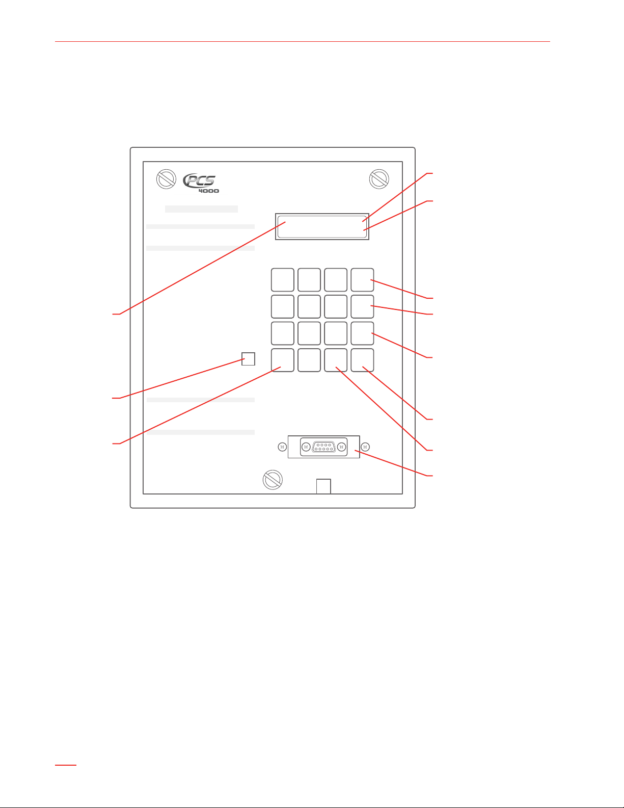
Current
well status
Time remaining
in hrs.:min.:sec.
When A-valve is closed:
- Casing pressure
- Tubing pressure
- Line pressure
When A-valve is open:
- Casing pressure
- Flow rate
- Line pressure
Opens A-valve
Closes A-valve and
B-valve
Used with other keys
to access functions that
control B-valve.
Example: B ON opens
B-valve
Clears current entry
and backspaces
Sets program functions
Reads reports
and function
values
Power
On/Off
Local operator input (LOI)
serial port for connection
to laptop computer
PRODUCTION CONTROL SERVICES, INC.
1-800-619-2241
PCSplungerlift.com
THIS PCS CONTROLLER IS MANUFACTURED BY PCS, INC © 1998
PATENT NO.6,196,324 B1
OPERATING INSTRUCTIONS
READ B 30: Serial Number
Read CE: Version Number
MANUAL VALVE CONTROL
ON Open A Valve (Sales)
OFF Close A & B Valves
B ON Open B Valve (Vent)
PROGRAM AND READ SETTINGS
PROGRAM Press: SET, Function Key
READ Press: READ, Function Key
ON A Valve Open Time
OFF Close Time
B ON B Valve Open Time
#00 Battery And Solar Conditions
#02 A Valve Delay (Sales) Time
#03 Mandatory Shut In Time
#05 Plunger Fall Time
#08 Delay Close Time
Sensor Status (On or Off)
#09 Auxillary Close Delay
(On = No Delay or Off = Close Delay)
#11 Controller Operating Mode
Differential Open Pressure
#12 Casing-Tubing or Casing-Line
#13 Casing PSI Increase (Casing Dip) Close
#14 High Line Pressure Close
#15 Low Line Pressure Close
#16
Activate and Calibrate Trans #1/Casing
#17
Activate and Calibrate Trans #2/Tubing
#18 Activate and Calibrate Trans #3/Line
#20 Casing Drop Pressure
#21 Casing Peak Build Time
#24 Load Factor
#26 Equalize Time / C Valve
#90 Scan / Set Entire Program
B VALVE SETTINGS
B-0 A Valve Closed When B is Open (Yes or No)
B-2 B Valve Display Time
B-4 B Valve Plunger and Valve Counts
B-7 B Valve Open and Close Times
B-8 Line Delay Times
PLUNGER HISTORY
History Press: READ, Function Key
Clear Totals Press: SET, Function Key, CE
#04 A Valve Plunger and Valve Counts
#06 Plunger Travel Times (Last 25) Avg. Run
#07 A Valve Open and Close Times
A & B Plunger and Valve Counts
#10 Plunger Travel Times (Last 25)
#19 Open and Close Times (Last 10)
CLOSE 0:00:00
C315 T250 L150
1 2 3
ON
4 5 6
OFF
7 8 9 B
READ
0
SET CE
POWER
ON/OFF
DISPLAY STATUS HRS:MIN:SEC
BasiC operations
Controller’s Faceplate
Figure 1 shows the controller’s faceplate with the power on/off switch, status display, keypad, and serial port for local
operator input.
PCS 4000 SINGLE WELL CONTROLLER
Figure 1 – Controller’s Faceplate
2

USER GUIDE
PCS 4000 SINGLE WELL CONTROLLER
Turning the Controller On and Off
To turn the PCS 4000 Single Well Controller on or off,
insert a screw driver into the slot marked POWER ON/
OFF. See Figure 1.
Move the toggle switch to the left to turn the controller on.
Move the toggle switch to the right to turn the controller
off.
The plunger program does not run while the controller is
off. When you turn the controller on, it closes the A-valve
and starts counting down the FALL TIME (see step 1 on
page 7).
Status Display
After you turn the PCS 4000 Single Well Controller on, the
status display remains on. The controller never sleeps.
The rst line of the status display shows the current well
status and the time remaining.
When the A-valve is closed, the second line of the status
display shows the casing pressure, tubing pressure, and
sales line pressure.
Operating the A-Valve and B-Valve Manually
Open the A-Valve = ☛ ON
Press ON.
ON overrides all programmed functions such as FALL
TIME and MANDATORY SHUT-IN TIME.
ON does not override safeguard functions such as
LOW LINE CLOSE PRESSURE and HIGH LINE CLOSE
PRESSURE.
Open the B-Valve = ☛ B ON
Press B ON.
Close the A-Valve (and B-Valve if Used) = ☛ OFF
Press OFF.
OFF overrides all programmed functions such as OPEN
TIME and DELAY TIME (SALES).
Reading Reports and Program Functions
Read a Report or the Value of a Single Program Function
Press READ.1
Example:
CLOSE 0:00:00
C315 T250 L150
When the A-valve is open, the second line shows the
casing pressure, ow rate, and sales line pressure.
Example:
A-OPEN 0:14:22
C315 F123 L150
Units of Measurement
Time is in hours:minutes:seconds.
Example: 08:15:00
Pressure is in pounds per square inch (psi).
Example: 00100
Depending on the setting of the METRIC function (SET
33), the unit of measurement for ow rate is either
thousand cubic feet (mcf) or thousand cubic meters
(E3M3).
The status display shows:
READ:
Enter the number of the report or function you want to 2
display. Example: 10.
Read the Values of All Program Functions = ☛ READ 90
For a list of the program functions, see “READ 90
Program Function List” on page 4.
Setting Program Functions
Set a Single Program Function
Press SET.1
The status display shows:
SET:
Enter the number of the function you want to set. 2
Example: 05.
Enter the value for the function. See 3 “Units of
Measurement” on this page.
To exit the function without changing its value, press
CE.
Set All Program Functions = ☛ SET 90
For a list of the program functions, see “SET 90 Program
Function List” on page 4.
3

USER GUIDE
report and program FunCtion reFerenCe
The tables in this section cross-reference the reports and
program functions described in this User Guide.
Reports
Report READ Page
Software Version Report CE 6
Battery Status Report 00 6
Status of A-Valve when B-Valve Is Open B0 9
A-Valve and Plunger Counts History 04 5
B-Valve and Plunger Counts History B4 5
Plunger Travel Time History 06 5
A-Valve Total Time Report 07 5
B-Valve Total Time Report B7 5
Valve/Plunger Counts History, Total Time
Reports, and Plunger Travel Time History
Time Open and Closed History 19 6
Modbus Address Report 22 6
PCS 4000 SINGLE WELL CONTROLLER
Clearing Report Values
Program Function SET Display Name Page
Clearing Report
Values
Program Functions
READ 90 Program Function List
Press READ 90 to display the current times, pressures,
and ow rate values programmed for all functions listed in
the table on the right side of this page.
SET 90 Program Function List
Press SET 90 to program all functions listed in the table
on the right side of this page.
Additional Program Function
To program this function, press SET B 0.
To display its current value, press READ B 0.
Program Function
Status of A-Valve
when B-Valve Is Open
10 ZERO ALL TOTALS 6
SET or
READ Display Name
B0 A OPEN W/ B VAL. 9
10 5
Page
Program Function
OPEN TIME ON A OPEN TIME 9
CLOSE TIME OFF CLOSE TIME 11
DELAY TIME (SALES) 02 A DELAY TIME 13
MANDATORY
SHUT-IN TIME
B OPEN TIME B ON B OPEN TIME 9
B DELAY TIME B2 B DELAY TIME 13
FALL TIME 05 FALL TIME 9
DELAY CLOSE TIME 08 DELAY CLOSE TIME 10
Sensor Operation 09 SENSOR?
A-Valve Location
(local or remote)
B-Valve Location
(local or remote)
C-Valve Location
(local or remote)
Operating Mode 11 1. TIME 2. T-L
DIFFERENTIAL
OPEN PRESSURE
DIFFERENTIAL
CLOSE PRESSURE
(DIP)
HIGH LINE CLOSE
PRESSURE
DELAY LINE CLOSE
TIME
LOW LINE CLOSE
PRESSURE
CASING DROP
PRESSURE
CASING PEAK TIME 21 CASING TIME 11
LOW FLOW RATE 23 MIN. FLOW RATE 12
LOAD FACTOR 24 LOAD FACTOR 11
CRITICAL FLOW K
FACTOR
EFM Device Setup 31 READ REMOTE
Flow Rate Unit of
Measurement
B LOW FLOW RATE 35 B LOW FLOW RATE 12
B LOW FLOW
DELAY TIME
SET or
READ Display Name
03 MAND. SHUT-IN 10
SET SENSOR
60 VALVE A LOCATION none
61 VALVE B LOCATION none
62 VALVE C LOCATION none
3. C-T 4. C-L
12 OPEN PRESSURE 9
13 CLOSE PRESSURE 10
14 HIGH LINE PRES. 13
B8 LINE DELAY TIME 13
15 LOW LINE PRES. 13
20 CASING DROP PRS. 12
25 TURNER CRIT
FLOW CONSTANT
FLOW
READ ACCUM
FLOW
SELECT EFM TYPE
33 METRIC 3
36 B LOW FLOW
DELAY
Page
9
9
12
9
12
4

Controller reports
Plunger Travel Time History = ☛ READ 06
This report provides information about the 25 most recent
plunger travel times. The rst display shows the number
of times the plunger surfaced and the average travel time.
Example:
GOOD RUNS: 25
AVE: 0:08:22
USER GUIDE
PCS 4000 SINGLE WELL CONTROLLER
Example:
A PLUNGER= 92
A VALVE = 96
In the example:
A VALVE = 96 shows that the A-valve opened 96 times.
A PLUNGER= 92 shows that the plunger arrived 92
times while the A-valve was open.
96–92=4. The plunger did not arrive 4 times while the
A-valve was open.
Use the READ button to scan through the report.
The next 25 displays show the 25 most recent plunger
travel times.
This example shows the most recent plunger run. The
plunger surfaced after 8 minutes and 15 seconds of
OPEN TIME.
LAST PLUNGER- 0
A 0:08:15
This example shows the 2nd most recent plunger run.
LAST PLUNGER- 1
A 0:08:15
This example shows the 25nd most recent plunger run.
LAST PLUNGER-24
A 0:08:15
This example shows the most recent plunger run. The
plunger surfaced after 10 minutes and 40 seconds of
OPEN TIME and B OPEN TIME.
LAST PLUNGER- 0
B 0:10:40
This example shows the most recent plunger run. The
CASING DROP PRESSURE was reached before the
plunger arrived.
LAST PLUNGER- 0
C 0:09:26
This example shows the most recent plunger run. The
plunger did not surface.
LAST PLUNGER- 0
NO PLUNGER
To exit the report at any display, press CE.
Valve/Plunger Counts History, Total Time Reports, and
Plunger Travel Time History = ☛ READ 10
This reporting option displays the 2 Valve and Plunger
Counts Histories (READ 04 and READ B4), the 2 Total
Time Reports (READ 07 and READ B7), and the Plunger
Travel Time History (READ 06). To display the next report,
press READ.
A-Valve and Plunger Counts History = ☛ READ 04
This report shows how many times the A-valve opened,
and how many times the plunger arrived while the A-valve
was open.
Note: If the well has a B-valve, this report shows 2 A-valve
counts for each B-valve count in the B-Valve and Plunger
Counts History. If the plunger did not arrive 4 times while
the A-valve was open, the plunger may have arrived up to
2 times while the B-valve was open.
B-Valve and Plunger Counts History = ☛ READ B4
This report shows how many times the B-valve opened,
and how many times the plunger arrived while the B-valve
was open.
Example:
B PLUNGER= 2
B VALVE = 2
In the example:
B VALVE = 2 shows that the B-valve opened 2 times.
B PLUNGER= 2 shows that the plunger arrived 2 times
while the B-valve was open.
A-Valve Total Time Report = ☛ READ 07
This report shows 2 times of up to 999 hrs., 59 min., 59
sec. accumulated since the report was last cleared:
Total OPEN TIME and DELAY TIME (SALES).
Total time that the controller was closed. MANDATORY
SHUT-IN (if any), FALL TIME (if any), and CLOSE TIME
are accumulated under TOT CLS time.
Example:
A TOTAL 16:31:13
TOT CLS 8:12:45
B-Valve Total Time Report = ☛ READ B7
This report shows 2 times of up to 999 hrs., 59 min., 59
sec. accumulated since the report was last cleared:
Total B OPEN TIME.
Total time that the controller was closed. MANDATORY
SHUT-IN (if any), FALL TIME (if any), and CLOSE TIME
are accumulated under TOT CLS time.
Example:
B TOTAL 1:24:32
TOT CLS 8:12:45
5

USER GUIDE
Clearing Report Values = ☛ SET 10
The display shows:
ZERO ALL TOTALS
ON=YES OFF=NO
Press the ON button to clear all of the valve and plunger
counts (READ 04 and READ B4) and total times (READ 07
and READ B7).
This option does not clear the Plunger Travel Time History
(READ 06) and the Time Open and Closed History (READ
19). History information is always available.
Note: Press the OFF button to exit the Clearing Report
Values function without clearing any of the report values.
Time Open and Closed History = ☛ READ 19
This report provides information about the last 10 times
the A-valve was open, and the last 10 times the A-valve
was closed.
OPN-0 and CLS-0 show the most recent open and
close information.
OPN-1 and CLS-1 show the 2nd most recent open and
PCS 4000 SINGLE WELL CONTROLLER
close information.
OPN-9 and CLS-9 show the 10th most recent open
and close information.
Example:
OPN-0 O 00:20:00
CLS-0 C 00:15:00
OPN information shows:
How long the A-valve was open. Time Open includes:
OPEN TIME
DELAY TIME (SALES)
DELAY CLOSE TIME (if any)
Time Open does not include B OPEN TIME (if any).
A letter that explains why the A-valve closed:
F = low ow rate input or critical ow K value input
G = switch gauge input
H = high sales line pressure input
L = low sales line pressure input
M = manual close
O = open time ran out
S = increase in casing pressure input
U = drop in casing pressure input
Note: If the A-valve opens because a close input stops,
there is no letter. For example, the A-valve closes in
response to a close input caused by low or high sales line
pressure. When the sales line pressure returns to normal,
the A-valve opens. The CLS information does not include
a letter.
Operating Mode Report = ☛ READ 11
The controller’s operating mode:
TIME MODE (mode 1)
TUBING-LINE MODE (mode 2)
CASING-TUBING MODE (mode 3)
CASING-LINE MODE (mode 4)
For more information, see “How Pressure Operation
Works” on page 7.
Battery Status Report = ☛ READ 00
This report displays the current voltage of the battery and
the solar panel.
Example:
BATTERY = 7.00V
SOLAR = 9.24V
Sensor Status = ☛ READ 09
This report shows whether the sensor is ON or OFF.
Note: The sensor must be ON to read the sensor input.
When using the Time operating mode, you can set the
sensor to OFF. PCS recommends setting the sensor to off
only if you are not running a plunger.
Software Version Report = ☛ READ CE
This report displays the chip and software version
numbers.
Example: VERSION 138-41
Modbus Address Report = ☛ READ 22
This report displays the controller’s modbus address.
Example: MODBUS ADDR:005
Important! Do not change the modbus address.
CLS information shows:
How long the A-valve was closed
A letter that explains why the A-valve opened:
C = CLOSE TIME counted down to zero
D = differential open pressure input
M = manual open
R = load factor input
T = casing time input
6
 Loading...