

Page 1
Combination Vortex and Plate Shaker
13204-31
Instructions for Use
Page 2

Combination Shaker
Instructions for Use
2
Contents
1 Symbols Used in this Instruction Manual ......................................................... 4
2 Safety Precautions and Limitations of Use ...................................................... 5
3 Regulatory Limitations of Use .......................................................................... 9
4 Unit Description ............................................................................................. 10
5 Unit Installation .............................................................................................. 12
6 Unit Operation ................................................................................................ 13
6.1 Overview of Operating Controls ..................................................................... 13
6.2 Unit Shutdown Procedure .............................................................................. 16
6.3 Shaking Plates and Tubes ............................................................................. 17
6.3.1 Shaking with Free-style Parameters .............................................................. 18
6.3.2 Pre-defined Shaking Programs ...................................................................... 22
6.3.3 Using PCR Plates in the PCR Adapter Block (Type 1) .................................. 24
6.3.4 Using Micro Tubes in the Tube Adapter Blocks (Type 1, 2 and 3) ................ 24
6.3.5 User-defined Mixing Programs ...................................................................... 24
6.4 Vortexing Tubes ............................................................................................. 25
6.4.1 General Tube Vortexing ................................................................................. 25
6.4.2 Batch Vortexing of Tubes ................................ Error! Bookmark not defined.
6.4.3 User-defined Vortexing Programs ................................................................. 28
7 Advanced Set-up Features ............................................................................ 30
7.1 Shaker Program Tools ................................................................................... 30
7.1.1 Favorite Programs List ................................................................................... 31
7.1.2 Creating a New User-defined Program .......................................................... 32
7.1.3 Changing the Program ID, Info, Adapter Type and Parameters .................... 33
7.1.4 Deleting a User-defined Program .................................................................. 34
7.2 Profiled Mixing Programs ............................................................................... 35
7.3 Vortexer Program Tools ................................................................................. 39
7.4 User Preferences and Options ...................................................................... 40
7.4.1 Beeper and Button Click Volume ................................................................... 41
7.4.2 LCD Backlight Brightness Level .................................................................... 41
7.4.3 Cooling Fan Operating Mode ......................................................................... 41
7.4.4 Program Set-up Protection Mode .................................................................. 41
7.4.5 Vortexer Auto-start Mode ............................................................................... 42
7.4.6 Standby Mode ................................................................................................ 42
8 Maintenance and Servicing............................................................................ 43
8.1 Replacing the Unit Fuse ................................................................................ 43
8.2 Routine Cleaning and Inspection ................................................................... 44
8.3 Decontamination Procedure .......................................................................... 45
8.4 Transportation and Storage ........................................................................... 46
8.5 Product Disposal ............................................................................................ 46
9 Troubleshooting ............................................................................................. 47
10 Warranty and Returns .................................................................................... 49
11 Technical Specifications ................................................................................ 50
12 Glossary of Terms and Abbreviations ............................................................ 51
Page 3

Combination Shaker
Instructions for Use
3
Figures
Figure 1: Front and Rear Unit Views ....................................................................... 10
Figure 2: Unit Label and Mains Power Inlet ............................................................. 11
Tables
Table 1: Advisory Symbol Meanings.......................................................................... 4
Table 2: Key for Figure 1 and Figure 2 .................................................................... 10
Table 3: Unit Accessories ........................................................................................ 11
Table 4: Page Selection Tabs .................................................................................. 13
Table 5: Button Quick Reference ............................................................................. 15
Table 6: Menu Structure and Button Presses .......................................................... 16
Table 7: Supported Plate and Tube Types .............................................................. 17
Table 8: Pre-defined Mixing Programs .................................................................... 22
Table 9: Supported Vortexer Tube Types ................................................................ 25
Table 10: Program Tools Options ............................................................................ 31
Table 11: Program Editing Functions ...................................................................... 33
Table 12: Program Profile Step Parameters ............................................................ 35
Table 13: Program Profiling Functions .................................................................... 37
Table 14: Profile Editing Functions .......................................................................... 39
Table 15: User Preferences and Options ................................................................ 40
Table 16: Protected Function Buttons ..................................................................... 42
Table 17: Troubleshooting Tips ............................................................................... 47
Table 18: Unit Error Codes ...................................................................................... 48
Page 4
Combination Shaker
Instructions for Use
4
1 Symbols Used in this Instruction Manual
The following advisory symbols are used in this manual.
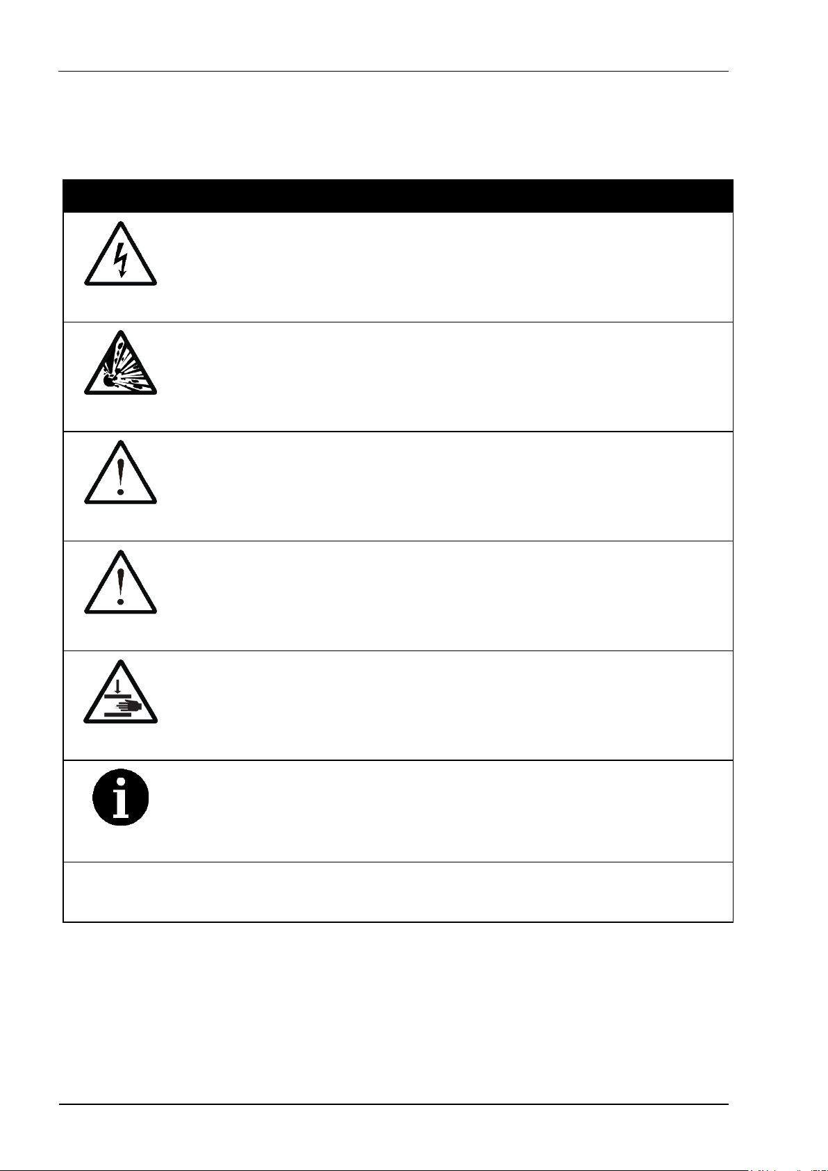
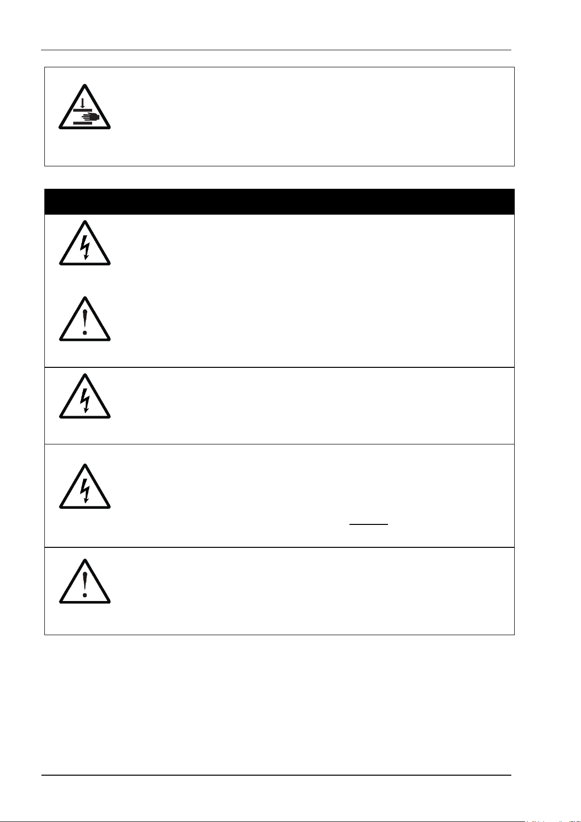
Table 1: Advisory Symbol Meanings
DANGER
Indicates a Risk of Electric Shock which could, if not avoided,
result in severe injury or death.
DANGER
Indicates a Risk of Explosion which could, if not avoided,
result in severe injury or death.
WARNING
Indicates a hazardous situation which could, if not avoided,
result in severe injury or death; or severely damage the unit.
CAUTION
Indicates a hazardous situation which could, if not avoided,
result in minor or moderate injury; or degrade or impair the
functionality of the unit.
CAUTION
Indicates a Risk of Crush hazard due to moving parts which
could, if not avoided, result in minor or moderate injury.
INFO
Advisory or other useful information.
NN
Refer to “section NN” for more details.
Page 5
Combination Shaker
Instructions for Use
5
2 Safety Precautions and Limitations of Use
It is essential that all users of this equipment have fully read and understood
the following safety precautions and limitations of use before installing or
operating the Combination Shaker unit.
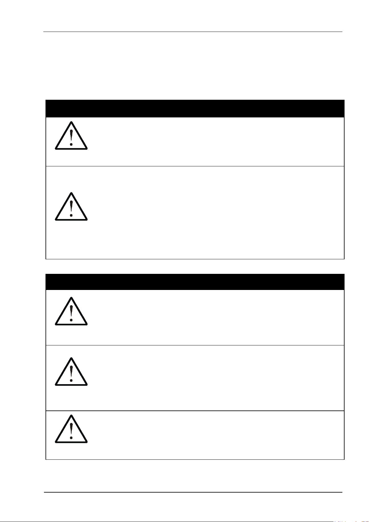
IMPORTANT
WARNING
The protection provided by this equipment may be impaired if
it is not used in a manner described in this manual.
WARNING
It is essential that the user of this equipment is aware of the
potential hazards associated with the unit and its accessories.
All operators should be familiar with the safety precautions
and warnings given in these instructions before attempting to
operate the unit.
Improper use of this unit or its accessories may impair their
functionality and invalidate the manufacturer’s warranty.
Unit Handling Precautions
CAUTION
Care should be taken not to drop the unit or subject it to rough
physical handling, both during normal use and during
transportation and storage.
Do not use the unit if it shows any signs of damage or wear.
WARNING
The unit should be held and supported in both hands when
lifting or moving. Do not lift the unit by the mixer or vortexer.
The base of the unit is cast from solid metal and is designed
to be heavy. Care should be taken to avoid trapping fingers
under unit when placing it down on a solid surface.
CAUTION
Care should be taken not to knock the LCD display.
Do not use excessive force when pressing the touchscreen
buttons or when cleaning it.
Page 6

Combination Shaker
Instructions for Use
6
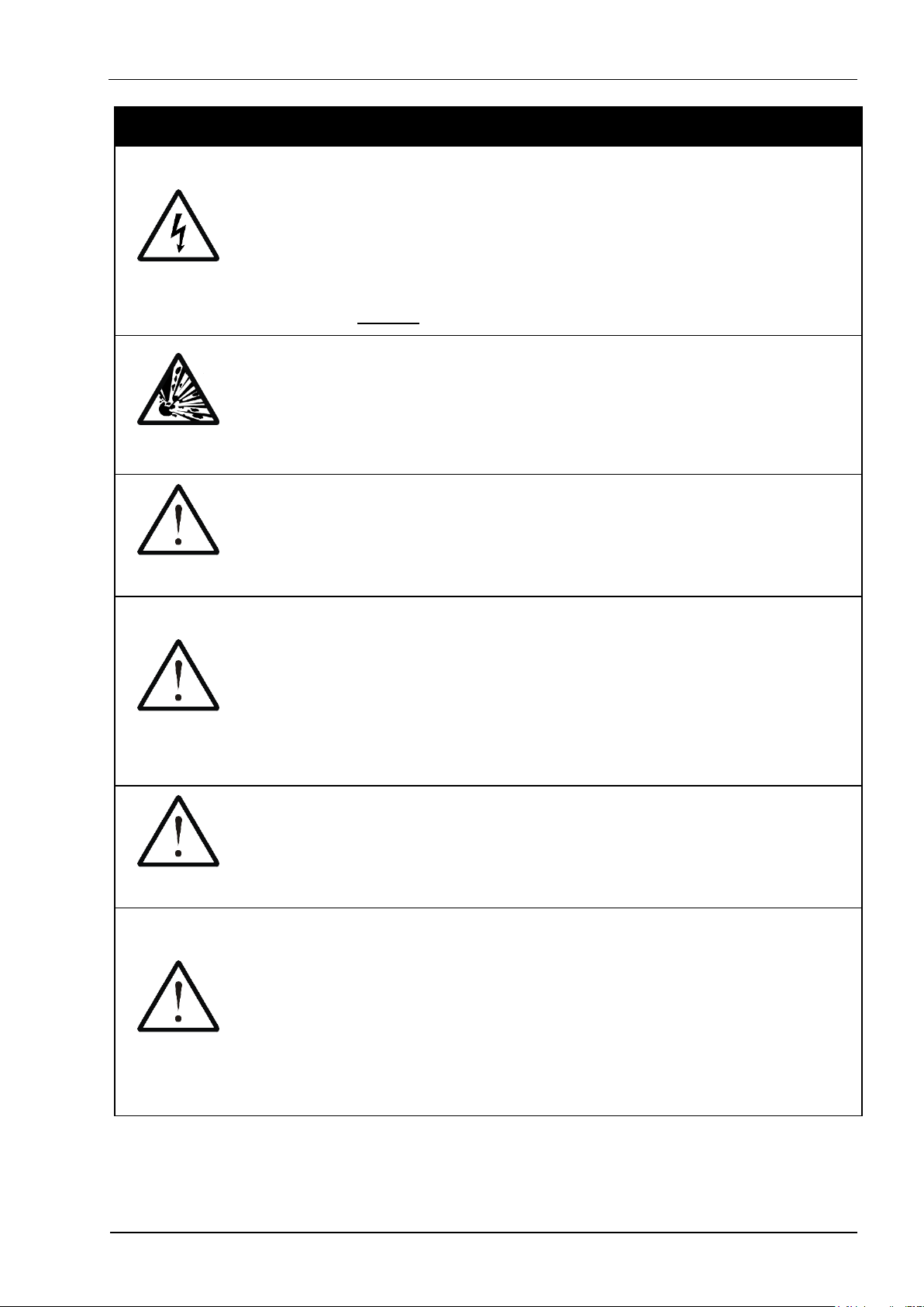
Unit Installation and Operating Environment
DANGER
WARNING
The Combination Shaker unit is designed for indoor laboratory
use only.
The acceptable operating temperature range is 10ºC to 38ºC,
with a relative humidity of 20% to 85% non-condensing, at a
maximum altitude of 2000m above sea level.
If the unit is stored in conditions outside of these ranges, it
must be left to stand unpowered until it has acclimatised to
within these environmental limits before being powered.
DANGER
Use only the AC mains power cord provided with the unit or as
specified in section 11.
The unit must be connected to a suitably earthed mains
supply, with appropriate earth-leakage and over-current
protection.
WARNING
Always ensure that the mains power connector is securely
inserted into the rear of the unit, and any excess power cord
does not pose a potential trip or pull hazard.
DANGER
Do not operate the unit in any area which is, or has been, or is
thought to have been exposed to explosive or flammable
gases, vapours or liquids.
WARNING
The unit must be installed and operated on a solid, stable,
vibration-free and level working surface; ensuring that the
ventilation slots on the underside of the unit are not blocked.
CAUTION
The unit can create strong vibrations at high speeds which
may cause objects positioned near to it to move.
Do not place easily movable objects near the unit; or ensure
that such objects are appropriately secured.
Page 7
Combination Shaker
Instructions for Use
7
General Operating Precautions
DANGER
Ensure that the power is switched off at both the AC mains
supply outlet and at the back of the unit before inserting or
removing the mains power cord.
However, if a spillage occurs in or over the unit, always switch
the power off and unplug the power cord at the mains supply
outlet first, before attempting to deal with the spill.
DANGER
The unit is intended for use with aqueous solutions and
suspensions only.
Never use the unit to mix any explosive, volatile or highly
reactive substances or chemicals.
WARNING
To avoid liquid spills and possible cross-contamination of
samples, only use sealed plates and closed tubes when
mixing and vortexing.
WARNING
Injury can occur from flying plates and tubes if they are not
correctly inserted, or if the maximum recommended mixing
speed or total load weight is exceeded.
Always ensure that plates, adapter blocks and tubes are
correctly and securely inserted, and that plate dimensions
comply with the ANSI/SBS Standards for Microplates.
WARNING
Serious injury can occur from improper vortexing of tubes, and
tubes may be damaged, broken or destroyed.
Never vortex tubes made of glass or other fragile material.
WARNING
Injury or contamination can occur from sample material being
expelled from the plates or tubes whilst mixing and vortexing.
Only ever mix and vortex in sealed plates and closed tubes.
Always follow prescribed laboratory procedures and use
appropriate personal protective equipment (PPE, such as
gloves, clothing, goggles, etc) when handling samples.
Page 8
Combination Shaker
Instructions for Use
8
CAUTION
There is a possible finger crush hazard due to moving parts.
Do not remove or replace any consumables, tubes or Adapter
Blocks whilst the plate mixer is running.
Do not remove the vortexer pad when the unit is switched on.
Unit Maintenance and Serviceability
DANGER
WARNING
There are no user or operator serviceable parts inside the
unit.
Do not remove the unit casework.
Removal of the unit’s casework will void the manufacturer’s
warranty and may expose the user to a Risk of Electric Shock
resulting in serious injury or death.
DANGER
The externally accessible unit fuse will only blow under an
extreme internal fault condition. This fuse should only be
changed after the unit has been thoroughly inspected by a
qualified engineer. See section 8.1 for details.
DANGER
Always switch off the unit and disconnect the power cord
before performing any cleaning or decontamination procedure.
If liquid is spilt into or over the unit, switch off and disconnect
the power from the AC mains outlet before attempting to deal
with the spillage.
CAUTION
The use of harsh chemicals and cleaning agents may damage
the unit and degrade its performance.
Always follow the cleaning and decontamination procedures
specified in sections 8.2 and 8.3 of this instruction manual.
Page 9
Combination Shaker
Instructions for Use
9
3 Regulatory Limitations of Use
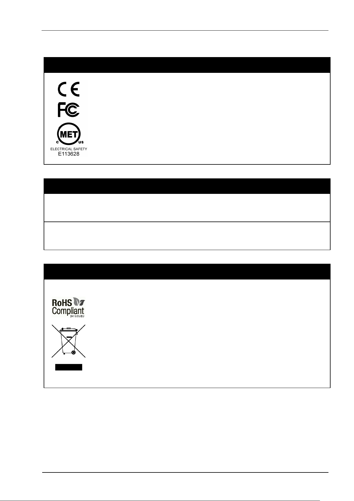
Declaration of Conformity
This product fulfils the essential requirements of the Low
Voltage Directive (LVD) 2006/95/EC and the EMC Directive
2004/108/EC, when installed and operated in accordance with
the instructions given in this manual.
The Combination Shaker unit has been type tested by TRaC
Global Ltd (UKAS accredited Testing Laboratory No 0026)
against the Safety and EMC Requirements listed below, and
issued Certificate Nos TRAC13SAF0012 and TRA-011466-38.
Safety and EMC Requirements
SAFETY
• EN 61010-1:2010, EN 61010-2-051:2003
• UL 61010-1:2001 2nd Edition (CAN C22.2 CSA 61010-1)
EMC
• EN 61326:2006, Class B
• FCC CFR 47 Parts 15.107 and 15.109, Class B
RoHS and WEEE Directive Compliance
This product is compliant with the requirements of the RoHS2
Directive 2011/65/EU for Electrical and Electronic Equipment.
Where applicable, the Combination Shaker unit should be
disposed of in accordance with the European Union WEEE
Directive 2002/96/EC on Waste Electrical and Electronic
Equipment.
Do not dispose of this product into unsorted municipal waste
or public landfill. Please refer to section 8.5 for details of how
to correctly dispose of this product.
The Combination Shaker unit is designed and manufactured under ISO 9001 by:
Integrated Technologies Limited
Viking House, Ellingham Way, Ashford, Kent, TN23 6NF
United Kingdom
Page 10
Combination Shaker
Instructions for Use
10
4 Unit Description
The combination vortex and shaker unit has the following features:
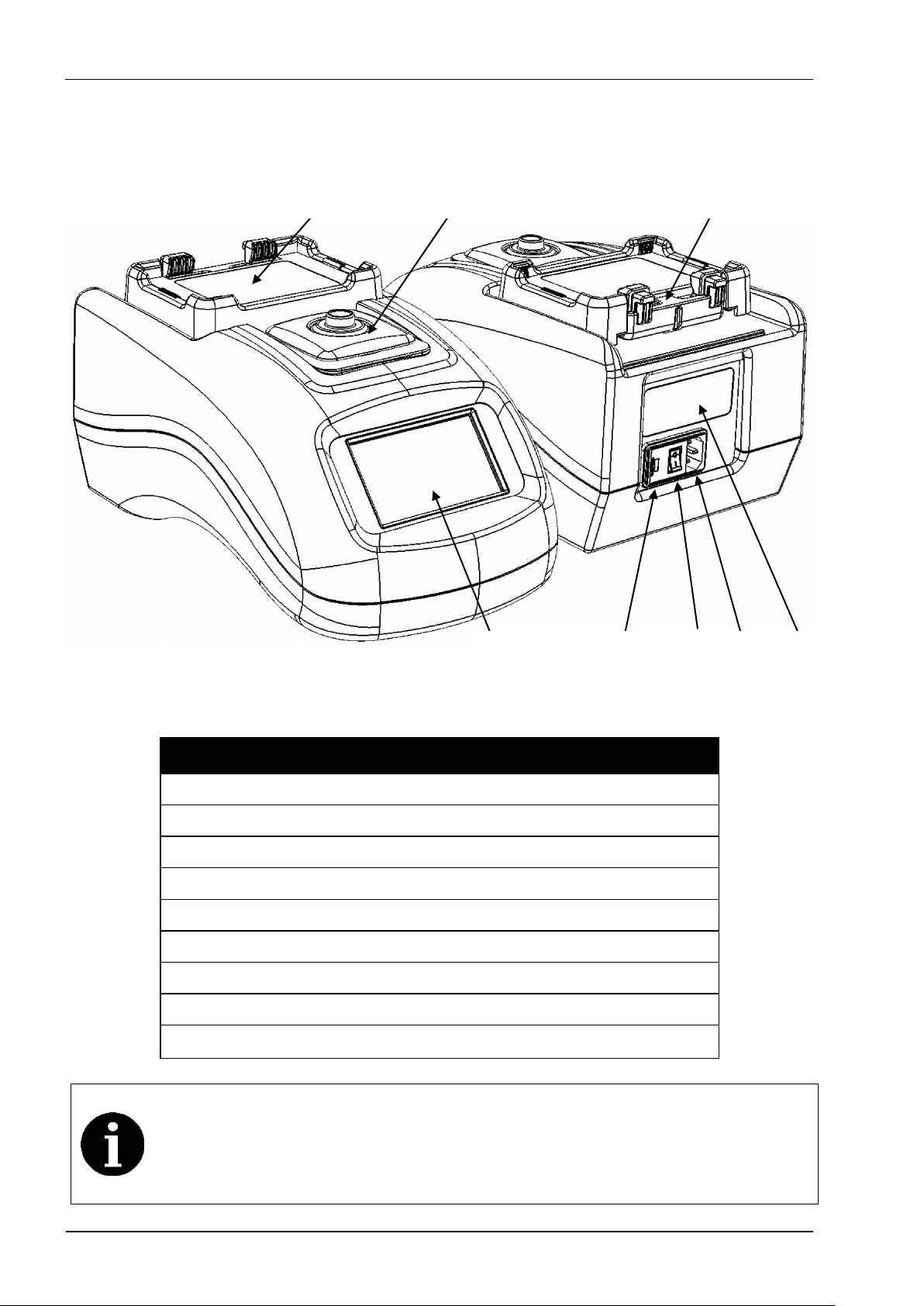
Figure 1: Front and Rear Unit Views
Table 2: Key for Figure 1 and Figure 2
LCD Touchscreen User Interface
6.1
Plate Shaker / Plate Holder
6.3
Plate Clamping Lever
6.3.2
Tube Vortexer
6.4
Unit Label and Serial Number
4
Mains Power Switch
5
Mains Power Inlet
5
External Fuse Access Cover
8.1
Mains Power and Fuse Ratings
11
The Combination Shaker has a unique automated plate clamping
lever () which allows plates and adapter blocks to be easily
inserted and removed from the plate holder () without disturbing
the samples.
Page 11
Combination Shaker
Instructions for Use
11
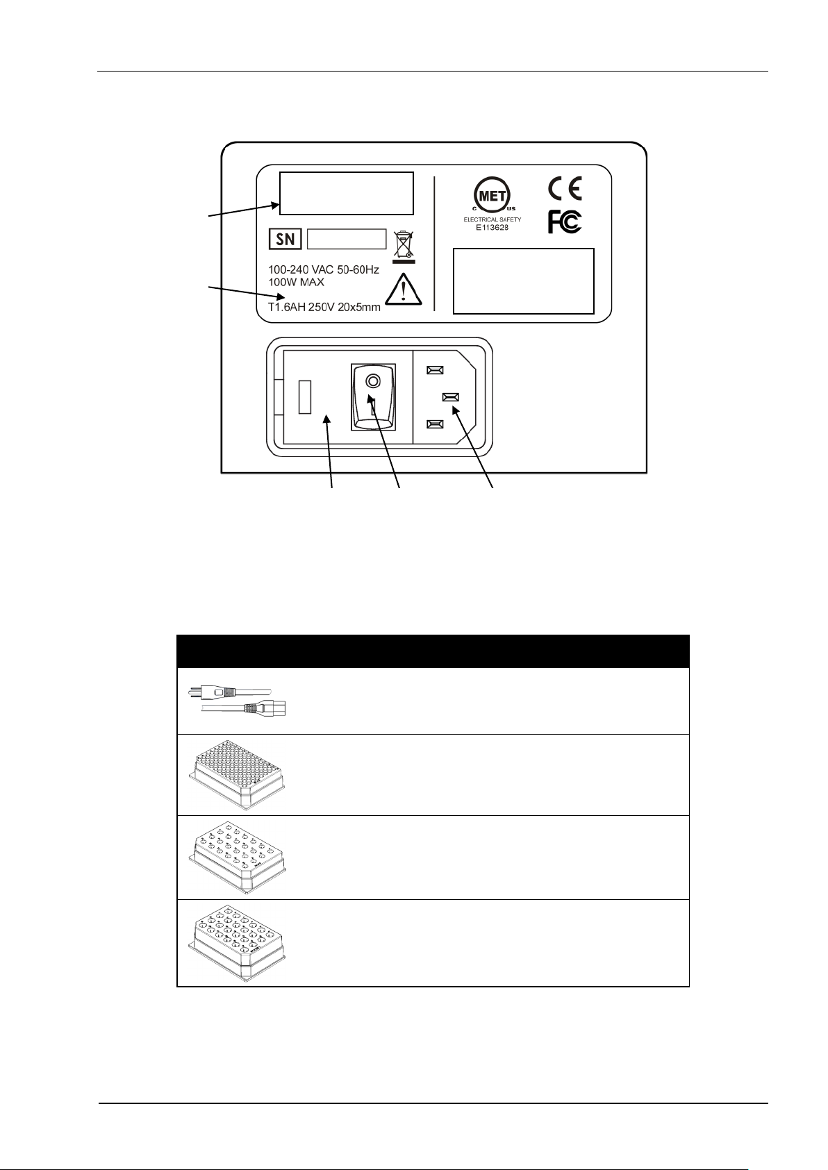
The unit label is located at the rear and provides general ratings information:
Figure 2: Unit Label and Mains Power Inlet
The unit is also supplied with the following accessories:
Table 3: Unit Accessories
Mains power cord (varies
according to country of use)
5
11
96 well PCR plate and 0.2ml tube
adapter block
6.3
6.3.3
24 well 0.5ml tube adapter block
6.3
6.3.4
24 well 1.5ml and 2.0ml tube
adapter block
6.3
6.3.4
Other optional accessories and specialty adapter blocks may be available on
request. Please contact Cole-Parmer for details.
Page 12
Combination Shaker
Instructions for Use
12
5 Unit Installation
Before installing the Combination Shaker unit, please check that the delivery
is complete (see Table 3) and that the unit and all accessory parts are intact
and free from any signs of transportation damage.
Please retain all packaging for future transportation and storage of
the unit and its accessories.
The Combination Shaker unit should be installed in a location which meets
the following requirements:
• Safe and suitable operating environment (see section 2)
• Solid, stable, vibration-free, level working surface
• At least 10cm clearance around the unit to adjacent objects and walls
• Earthed AC mains power connection (see section 11)
WARNING
Please also observe and abide by the Unit Installation and
Operating Environment safety precautions and preconditions
listed in section 2.
Install and test the Combination Shaker unit using the following procedure:
1. Place the Combination Shaker unit on the suitably selected working
surface (as specified above), ensuring that the ventilation slots on the
underside of the unit are not covered or blocked.
2. Connect the unit to the AC mains power outlet using the mains power
cord supplied (see section 4).
3. Switch the mains power on at supply outlet first, and then switch the
unit on using the power switch located at the rear of the unit.
4. Carry out a mixing test at the maximum required load and speed (using
the free-style MIX program described in section 6.3.1) to determine if
the grip between the unit and the working surface is sufficient to
prevent the unit from moving.
5. If the surface grip is sufficient, then the Combination Shaker unit should
not be moved from this installed position.
If the unit needs to be repositioned in the future, then the above installation
procedure should be repeated at the new location.
Page 13
Combination Shaker
Instructions for Use
13
6 Unit Operation
WARNING
Please ensure that you have read and fully understood all of
the Safety Precautions and Limitations of Use listed in
section 2 before attempting to operate the Combination
Shaker unit.
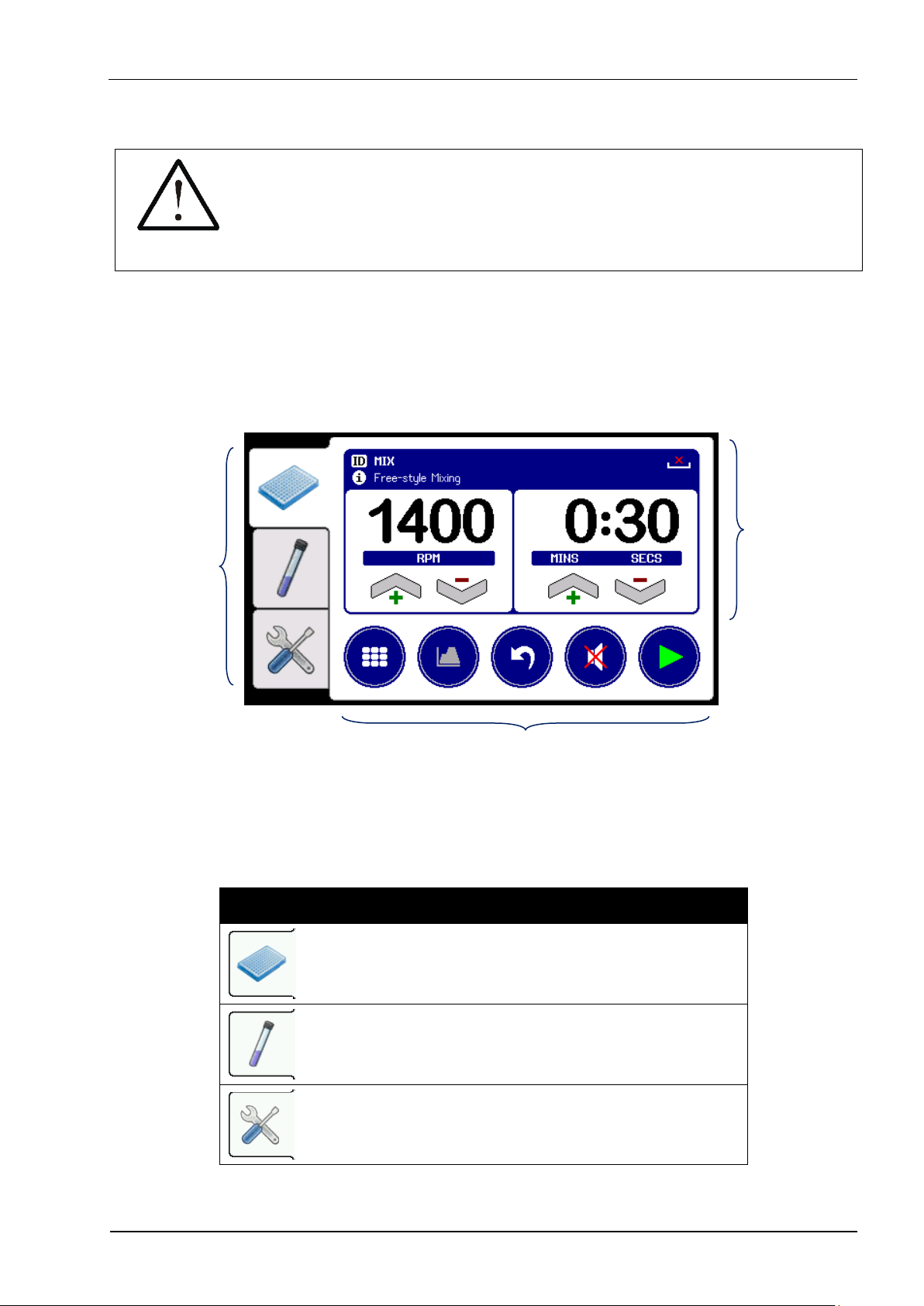
6.1 Overview of Operating Controls
The unit’s user interface consists of a color LCD touchscreen, with page
selection tabs down the left-hand side of the display and function buttons
along the bottom.
Page S
election
Tabs
Control and Status
Function and Option buttons
The Combination Shaker is designed to allow simultaneous operation of both
the plate shaker and tube vortexer, by providing easy mode switching using
the three page selection tabs shown in Table 4.
Table 4: Page Selection Tabs
Plate Shaker control and status
6.3
Tube Vortexer control and status
6.4
User Preferences and options
7.4
Page 14
Combination Shaker
Instructions for Use
14
The unit can store up to 200 shaking and vortexing programs (each with
different speed and time parameter settings) and is preloaded with eight
commonly used mixing programs.
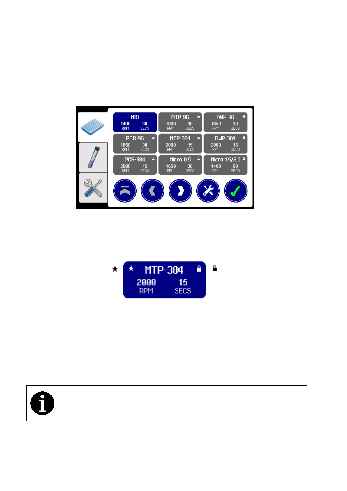
The program selection grid on the Mixer and Vortexer pages can store up to
100 programs each, arranged as a 3x3 scrolling grid list.
Home
Previous
Next
Tools
Accept
Each program grid button shows the program’s ID and the assigned speed
and time parameters.
Program ID
Favourite
Pre-defined
Speed
Time
To load a program, use the Home button to jump to the top of the program
grid list or the Next and Previous buttons to scroll through the list to highlight
the desired program, and then press the Accept button.
The Tools button allows access to advanced program set-up functions,
including user-defined programs and profiled mixing programs.
Once the unit has been fully set-up, the program set-up functions
can be disabled to prevent accidental modifications. Refer to
section 7.4 for details.
Page 15
Combination Shaker
Instructions for Use
15
The user interface and controls are described in detail in sections 6.3, 6.4
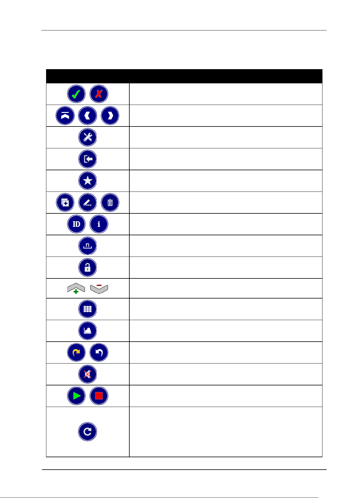
and 7. Below is a quick reference guide to the main button functions.
Table 5: Button Quick Reference
Accept or Cancel option
Home, Previous or Next program
6.3.1
Program Tools menu
7.1
Exit to previous menu
Add/remove Favourite program
7.1.1
New, Edit or Delete program
7.1
Change program ID or Info
7.1.3
Change user program Adaptor type
7.1.3
Unlock program speed and time
7.1.3
Increase or Decrease setting
6.3.1
Show Program selection grid list
6.3.1
Mixer program Profile edit
7.2
Open or Close clamping mechanism
6.3.1
Mute audible sounder
6.3.1
Start and Stop mixing or vortexing
6.3.1
Vortexer Restart mode
Error!
Reference
source
not
found.
Page 16

Combination Shaker
Instructions for Use
16
The user preferences and set-up option buttons are detailed in section 7.4.
Page 17
Combination Shaker
Instructions for Use
17
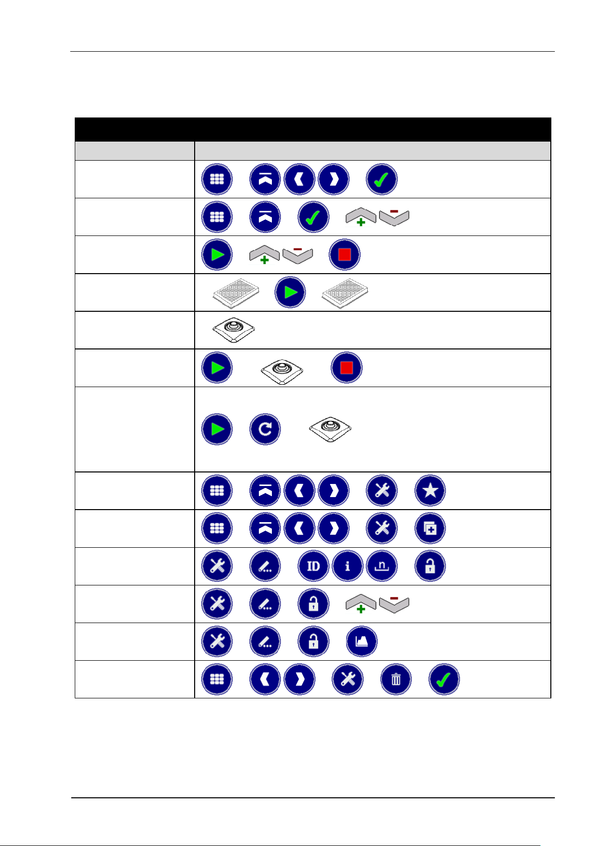
Table 6 provides an overview of the button presses required to perform
certain common actions.
Table 6: Menu Structure and Button Presses
Action
Button Sequence
Load a
program
→ →
6.1
Load free-style
program
→ → →
6.3.1
Fine tune freestyle program
→ →
6.3.1
Plate or Tube
Shaking
→ →
6.3.1
Automatic Tube
Vortexing
6.4.1
Manual Tube
Vortexing
→
→
6.4.1
Batch Tube
Vortexing
→ →
Error!
Reference
source
not
found.
Add favorite
program
→ → →
7.1.1
Create new
program
→ → →
7.1.2
Edit user-defined
program
→ → →
7.1.3
Change program
speed and time
→ → →
7.1.3
Edit profiled
program
→ → →
7.2
Delete userdefined program
→ → → →
7.1.4
Page 18

Combination Shaker
Instructions for Use
18
6.2 Unit Shutdown Procedure
After use, and before switch off the power to the unit, ensure that any plate or
adaptor block has been removed from the mixer plate holder, and then put
the unit into standby mode as described in section 7.4.6.
Page 19

Combination Shaker
Instructions for Use
19
6.3 Shaking Plates and Tubes
The shaker is designed to handle commonly used standard sample plates
and micro test tubes, as listed in Table 7.
Table 7: Supported Plate and Tube Types
Plate or Tube Type
Plate
Holder
Adapter Block Type
PCR 0.2 ml
0.5 ml
1.5 / 2.0 ml
x 1 2
3
MTP 96 and 384 Well
✓
DWP 96 and 384 Well
✓
Fully-skirted PCR Plate
✓
Semi-skirted PCR Plate
✓
Un-skirted PCR Plate
✓
PCR 0.2 ml Tubes
✓
0.5 ml Tubes
✓
1.5 ml Tubes
✓
2.0 ml Tubes
✓
CAUTION
All plates must conform to the ANSI/SBS Standard for
Microplates to ensure secure positioning in the plate holder.
The maximum permissible mixing speed for DWPs and
Adapter Blocks, or other plates over 80g, is 2000 RPM.
The Combination Shaker has eight pre-defined programs with recommended
mixing speeds and times to support the plate and tube types listed in Table 7.
Refer to section 6.3.2 and Table 8 for details.
The unit can also store over 90 user-defined mixing programs to easily
facilitate the use of other specific plates, sample types and fill volumes. See
section 6.3.5 for details.
Other specialist adapter blocks may be available on request.
Please contact your distributor with your specific requirements.
Page 20

Combination Shaker
Instructions for Use
20
6.3.1 Shaking with Free-style Parameters
The first program in the Mixer selection grid list is always the free-style MIX
program. This is a special program which allows the user to freely change the
mixing speed and time parameters to suit their immediate needs.
The shaker speed can be set between 200 RPM and 3000 RPM, and the
time between 5 seconds and 28 days.
Home
Previous
Next
Tools
Accept
To load the MIX program, select the Mixer page tab, then press the Home
button, followed by the Accept button.
→ → →
The plate clamping mechanism will automatically open, ready to accept the
plate or adapter block to be mixed.
Refer to section 6.3.2 for the use of the plate adapter blocks and
associated pre-defined shaking programs.
Page 21

Combination Shaker
Instructions for Use
21
The display now shows the current program parameters, which can be
manually changed using the Increase and Decrease buttons below the
speed and time values. Any changes are automatically saved in memory.
Programs
Profile
Clamp
Mute
Start
For the MIX program, the Increase and Decrease buttons are
always enabled to allow the speed and time parameters to be
freely changed, even when the mixer is running.
Place the plate or adapter block vertically down into the plate holder, making
sure it is sitting flat on the base of the holder.
WARNING
Injury can occur from flying plates and tubes if they are not
correctly inserted, or if the maximum recommended mixing
speed or total load weight is exceeded (see section 6.3).
Page 22

Combination Shaker
Instructions for Use
22
DANGER
Injury or contamination may also occur from sample material
being expelled from plates or tubes whilst mixing. Always use
sealed plates and closed tubes, and wear appropriate
Personal Protective Equipment (PPE).
Next press the Start button to begin the mixing process. The plate clamping
mechanism will automatically close to firmly grip the plate or adapter block
and the specified mixing program will be run.
The shaking timer will now count down each second until it reaches zero, or
the Stop button is pressed.
Stop
NOTE
The Combination Shaker unit has a vibration sensor which detects
if the mixer becomes unstable, and automatically decreases the
mixing speed (displaying the new RPM in red) to reduce the
vibration. If there is still too much vibration, mixing is aborted and
an E25 error displayed. See Table 18 for error code descriptions.
When shaking is complete, the unit beeps three times and the plate clamping
mechanism automatically opens so that the plate or adapter block can be
easily removed without disturbing the samples.
Page 23

Combination Shaker
Instructions for Use
23
The volume of the beeps at the end of mixing process can be
adjusted from the user Preferences page (see section 7.4.1) or
temporarily disabled by pressing the Mute button.
The display will return to the previous screen, ready to accept the next plate
to be mixed.
Pressing the Programs button will close the plate clamping mechanism and
return to the mixer program selection screen.
The Clamp button can be used to manually open and close the plate
clamping mechanism if required.
↔
Open
Close
NOTE
If the plate clamping mechanism is left open for longer than
5 minutes, it automatically closes to conserve energy. It can
be re-opened by simply pressing the Clamp open button.
Page 24

Combination Shaker
Instructions for Use
24
6.3.2 Pre-defined Shaking Programs
The unit has eight pre-defined shaking programs which support the
commonly used plates and micro test tubes listed in Table 7.
These programs are listed in Table 8, along with details of the pre-set
shaking speed and time parameters, the recommended well or tube fill level
and the required adaptor block type.
Table 8: Pre-defined Mixing Programs
Program
ID
Plate or Tube
Type
Speed
(RPM)
Time
(seconds)
Fill
Level
Adapter
Block
MTP-96
96 well MTP
1000
30
5 to 60%
x
DWP-96
96 well DWP
1650
30
5 to 50%
x
PCR-96
96 well PCR plate
0.2ml tubes or strips
1650
30
5 to 50%
1
MTP-384
384 well MTP
2000
15
10 to 60%
x
DWP-384
384 well DWP
2000
15
10 to 60%
x
PCR-384
384 well PCR plate
2600
15
10 to 50%
x
Micro 0.5
0.5ml micro tubes
1650
30
5 to 50%
2
Micro 1.5/2.0
1.5ml micro tubes
2.0ml micro tubes
1400
60
5 to 80%
3
Other shaking speeds and times can be selected using the freestyle MIX program (see section 6.3.1) or by creating a new userdefined program (see section 6.3.5 for details).
The procedure for shaking using a pre-defined program is similar to that
described in section 6.3.1 for the free-style MIX program.
First select the appropriate pre-defined program from the selection grid, and
then press the Accept button to load it.
→ → →
Page 25

Combination Shaker
Instructions for Use
25
The plate clamping mechanism will automatically open to accept the plate or
adapter block to be shook.
Programs
Profile
Clamp
Mute
Start
The adapter block type is displayed in the top right-hand corner of
the status area, or as ‘x’ if none is required. Refer to sections 6.3.3
and 6.3.4 for details relating to the use of specific adaptor blocks.
For pre-defined programs, the Increase, Decrease and Profile
buttons are always disabled to prevent the program parameters
from being modified. Refer to section 7.1.2 for details of creating
user-defined variants of the pre-defined programs.
Place the plate or adapter block into the plate holder, making sure it is sitting
flat on the base of the holder, and then press the Start button to close the
clamping mechanism and begin the shaking process.
The shaking timer will count down each second until it reaches zero, or the
Stop button is pressed.
When shaking is complete, the unit beeps and the plate clamping mechanism
automatically opens so that the plate or adapter block can be removed.
The display will return to the previous screen, ready to accept the next plate
to be shook, or press the Programs button to close the clamping mechanism
and return to the program selection screen.
The clamping mechanism can be manually opened or closed by pressing the
Clamp button.
Page 26

Combination Shaker
Instructions for Use
26
6.3.3 Using PCR Plates in the PCR Adapter Block (Type 1)
1. Insert the semi-skirted or unskirted PCR plate into 96 well adapter block
(see Table 7), making sure that it is level with the top of the block and that
it is securely and fully inserted.
2. Insert the adapter block into the plate holder on the unit.
6.3.4 Using Micro Tubes in the Tube Adapter Blocks (Type 1, 2 and 3)
1. Select the appropriate adapter block for the tube being used from Table 7.
2. Insert the micro test tubes into the adapter block, ensuring that they are
securely and fully pushed down in the wells.
3. Insert the adapter block into the plate holder on the unit.
4. After shaking, remove the adapter block from the unit and then remove the
micro tubes as required.
6.3.5 User-defined Shaking Programs and Profiles
The unit can store over 90 user-defined shaking programs, which can be
created by copying an existing program and then changing the program ID
and the speed and time parameters as required. See section 7.1.2 for
details.
User-defined mixing programs can also consist of a series of individually
defined program steps, each with different shaking parameters and run in
succession to produce a complex profiled mixing sequence. Refer to section
7.2 for details.
Page 27

Combination Shaker
Instructions for Use
27
6.4 Vortexing Tubes
The Combination Shaker tube vortexer is designed to operate at the same
time as the plate shaker and supports the following tube types:
Table 9: Supported Vortexer Tube Types
Tube Types
Vortexing Pad
15 ml screw top (sealed) skirted and unskirted tubes
✓
20 ml screw top (sealed) skirted and unskirted tubes
✓
50 ml screw top (sealed) skirted and unskirted tubes
✓
Micro test tubes and PCR tubes (sealed)
✓
Other generic 5 ml to 100 ml screw top plastic tubes
✓
NEVER USE: Open topped tubes
NEVER USE: Glass tubes or other fragile materials
NEVER USE: Flasks or other flat bottomed vessels
WARNING
Serious injury can occur from improper vortexing of tubes.
Never vortex open-topped tubes. Always use sealed tubes.
Never vortex tubes made of glass or other fragile materials.
Not suitable for flasks or other flat bottomed vessels.
The Combination Shaker has no specific pre-defined vortexing programs, but
instead allows up to 99 user-defined programs to be created and stored.
The vortexer speed can be set between 700 RPM and 3500 RPM, and the
time between 2 seconds and 60 seconds.
6.4.1 General Tube Vortexing
When the unit is switched on it automatically loads the most recently used
vortexing program, making it instantly ready to accept tubes.
Page 28

Combination Shaker
Instructions for Use
28
NOTE
It is not necessary to have the Vortexer page displayed for the
loaded program to run in Automatic mode - the vortexer will
operate whenever the pad is depressed. See sections Error!
Reference source not found. and 7.4.5 for details of available
vortexing modes.
Initially only the general purpose VORTEX program is available on the unit,
which allows the user to freely change the vortexing speed and time settings.
→ → →
The Vortexer page displays the current program settings, which can be
manually changed using the Increase and Decrease buttons below the
speed and time values.
Programs
Mute
Start
To vortex a tube, simply press the tube down onto the center of the vortexer
pad and vortexing will automatically start at the programmed speed.
The timer will count down each second, and vortexing automatically stops
when the timer reaches zero or the tube is removed from the pad.
Page 29

Combination Shaker
Instructions for Use
29
NOTE
The Combination Shaker unit has a vibration sensor which detects
if the mixer or vortexer has become unstable. If vortexing
generates too much vibration it will be automatically stopped and
an E35 error will be displayed. See Table 18 for error code
descriptions.
Alternatively, the Start button can be pressed to manually set the vortexer
running until either the timer reaches zero or the Stop button is pressed.
The speed can be adjusted whilst the vortexer is running to optimize the
vortexing performance depending on the tube type, and sample type and
volume being used.
When the optimum speed and time parameters have been found
using the VORTEX program, a new user-defined program can be
created to store these settings, and then quickly reloaded when
next required. See sections 6.4.2 and 7.3 for details.
The unit clicks once to acknowledge when the tube has been pressed onto
the vortexer pad, and beeps once when the programmed time has elapsed.
The volume of the click and beep at the start and end of vortexing
can be adjusted from the user Preferences page (see section
7.4.1) or temporarily disabled by pressing the Mute button.
When processing large batches of tubes, it can be desirable to set the
vortexer running and then apply each tube in rapid succession. This is done
by first loading the appropriate vortexing program, then pressing the Start
button to set the vortexer running, and then the Restart button.
→ → → →
Page 30

Combination Shaker
Instructions for Use
30
Restart
Stop
The Restart button illuminates and the timer starts counting upwards from
zero instead. Now, each time a tube is pressed onto the vortexer pad (or the
Restart button is pressed) the timer will reset back to zero.
When the programmed time is reached the unit beeps once to indicate that
the tube can be removed. However, instead of stopping immediately, the
vortexer runs-on for a further 5 seconds (with the time displayed in red),
allowing extra time for the next tube to be placed on the vortexer.
TIP
Press the tube firmly down onto the vortexer pad to reset the timer,
then relax the tube pressure so that there is still sufficient contact
with the pad to maintain the vortexing action but without being
unduly strenuous on the user.
If desired, this mode can be permanently enabled for all vorexting
programs by selecting the vortexer auto-Restart mode in the user
Preferences page. See section 7.4.5 for details.
6.4.2 User-defined Vortexing Programs
The unit can store up to 99 user-defined vortexing programs, each of which
can be tailored to suit different tube types, sample solutions and fill volumes.
To define a new program, first determining the optimum vortexing parameters
using the general VORTEX program (see section 6.4.1).
→ → → →
→ →
→
Page 31

Combination Shaker
Instructions for Use
31
Then create a copy of these settings with a new program ID (see section
7.1.2 for details).
→ → → →
Program ID
→
The new program is now ready to be used whenever next required.
Page 32

Combination Shaker
Instructions for Use
32
7 Advanced Set-up Features
The Combination Shaker unit also provides a number of advanced features
which allow the user to optimise the unit’s performance to meet their
individual needs.
7.1 Shaker Program Tools
As well as the pre-defined shaking programs, the user can create variants of
the existing ones. This allows new programs to be developed and optimised
for the specific plate type, sample assay and fill volume being used.
Home
Previous
Next
Tools
Accept
From the Mixer program selection screen, highlight the program to be copied
or modified and then press the Tools button.
Exit
Favorite
New
Edit
Delete
The tools menu options are summarized in Table 10 and explained in detail
in the following sub-sections.
Page 33

Combination Shaker
Instructions for Use
33
Table 10: Program Tools Options
Exit to program selection screen
Add/remove program from Favorite list
7.1.1
Create a New copy of the selected program
7.1.2
Edit selected program details and parameters
7.1.3
Delete the selected program
7.1.4
7.1.1 Favorite Programs List
Although the programs list can hold up to 100 pre-defined and user-defined
programs, typically only a small number of these will be regularly used.
Thus, to help organise the full list, preferred programs can be added to a
favorites list, which always appears at the top of the program selection list.
To add a program to the favorites list, simply highlight it in the selection grid,
press the Tools button and then the Favorite button. The program is marked
with a symbol in the top corner and moved to the top of the list.
A program can be removed from the favorites list by repeating this process.
The order of the programs within the favorites list is determined by
the order in which they were created and cannot be individually
rearranged.
Page 34

Combination Shaker
Instructions for Use
34
7.1.2 Creating a New User-defined Program
The unit can hold up to 100 shaking programs, 91 of which can be created
and defined by the user.
To add a new program, highlight an existing program from the selection list
which best matches the new program requirements, then press the Tools
button followed by the New button.
→ → →
The New button is unavailable when Protected mode is enabled.
See selection 7.4.4 for details.
This will create a new copy of the selected program and pop-up the program
ID editing keyboard:
Shift
Delete
Cancel
Left
Right
Accept
Use the QWERTY keyboard to enter a new name (ID) for the program, then
press the Accept button.
Try to limit the program ID to about 10 characters, as longer
names are displayed truncated in the program selection grid.
The new program has now been created and saved to memory, and can be
further modified using the editing functions described in section 7.1.3.
Page 35

Combination Shaker
Instructions for Use
35
7.1.3 Changing the Program ID, Info, Adapter Type and Parameters
To modify an existing user-defined program, highlight the program in the
selection grid, then press the Tools button followed by the Edit button.
→ → →
The Edit button is unavailable when Protected mode is enabled.
See selection 7.4.4 for details.
The Edit menu provides four top-level program editing functions.
Exit
ID
Info
Adapter
Unlock
These editing functions allow the program ID, Info text and associated
Adaptor block type to be changed, as described in Table 11.
Table 11: Program Editing Functions
Exit program editing menu
Edit the program ID using QWERTY keyboard,
which can be between 1 and 20 characters long
7.1.2
Edit the optional program Info text, which can be
up to 50 characters
Change the Adapter block type, by stepping
through the block types: ‘x’ (none) then 1 to 9
6.3
Unlock the program to allow the speed and time
settings to be changed or a profile to be defined
7.2
Page 36

Combination Shaker
Instructions for Use
36
Pressing the Unlock button enables the speed and time Increase and
Decrease buttons, and the program Profile editor button.
Programs
Profile
Clamp
Mute
Start
Once Unlocked, the Increase and Decrease buttons can be used whilst the
shaker is running to fine tune the mixing performance for the particular plate
type, sample solution and fill volume being used. Any changes to these
parameters are automatically saved to memory for next time.
Pressing the Profile button brings up the advanced program profiling menu,
which allows a sequence of up to 20 mixing parameter steps (speeds and
times) to be defined. Refer to section 7.2 for details.
7.1.4 Deleting a User-defined Program
To permanently delete a user-defined program, highlight the program in the
selection grid, then press the Tools button followed by the Delete button.
→ → →
The Delete button is unavailable when Protected mode is
enabled. See selection 7.4.4 for details.
Page 37

Combination Shaker
Instructions for Use
37
Cancel
Accept
Next press the Accept button to confirm the deletion, or Cancel to exit.
7.2 Profiled Shaking Programs
The Combination Shaker can store up to 91 user-defined mixing programs,
each of which can consist of a sequence of up to 20 individual mixing steps.
For each mixing step, the user can specify the following parameters:
Table 12: Program Profile Step Parameters
Parameter
Purpose
Range
RPM
Mixing speed *Automatically limited to 2000 RPM
when the program specifies the use of an adapter block
200 to 3000*
RPM
TIME
Mixing step duration specified in days,
hours, minutes and/or seconds
5 seconds
to 28 days
RAMP
Time allowed to smoothly transition between
the previous speed and the new RPM value
0 to 99
seconds
Hence, an example profiled program could consist of the following three
steps:
1) 1000 RPM, 30 seconds, 5 second ramp
2) 2000 RPM, 60 seconds, 10 second ramp
3) 1600 RPM, 5 minutes, 5 second ramp
Page 38

Combination Shaker
Instructions for Use
38
When the program is run, the unit executes each profile step in the sequence
in turn, showing the overall progress on the profile chart.
For profiled programs, the speed and time cannot be adjusted
using the Increase and Decrease buttons. These parameters can
only be altered via the Profile button.
To create a new profiled program, first create a new program as described in
section 7.1.2 above.
Then from the program Tools menu, press the Edit button followed by the
Unlock button to enable the Profile button, and then press the Profile button
to display the profile editing screen.
→ → → → →
Exit
Up
Down
Modify
Switch
Page 39

Combination Shaker
Instructions for Use
39
The Profile button accesses the profile editing menu, which consists of two
sets of function buttons:
Set 1
Set 2
Exit
Up
Down
Modify
Switch
Cut
Copy
Paste
Test
These button functions are described in Table 13.
Table 13: Program Profiling Functions
Set 1
Exit profile editing menu
Move profile step cursor Up one line
Move profile step cursor Down one line
Modify profile step parameters at cursor position
Switch to menu functions Set 2
Set 2
Switch back to menu functions Set 1
Cut and remove profile step at cursor position
Copy profile step at cursor position
Paste cut/copied profile step above cursor position
Test run mixer profile step at cursor position
Press the Modify button to change the profile step parameters (listed in
Table 12), using the numeric keypad to enter each new value followed by the
Accept button.
Page 40

Combination Shaker
Instructions for Use
40
The Accept button is also used to skip over unmodified values. For instance,
to change just the RPM, MINS and SECS values:
1) Enter the new RPM value followed by Accept
2) Press the Accept button twice (skips DAYS and HRS)
3) Enter the new MINS value followed by Accept
4) Enter the new SECS value followed by Accept
5) Press Accept again (skips RAMP)
When all six values had been accepted, the new settings are saved and the
display returns to the previous profile editing screen.
To enter a new step at the end of the sequence, move the cursor Down to
the empty “...” line and press the Modify button. Enter the new step
parameters as required, and then press the Accept button until all six values
have been set.
Repeat this process for up to 20 profiles steps.
Page 41

Combination Shaker
Instructions for Use
41
The Cut, Copy and Paste functions can be used to delete, move and
duplicate profile steps, as illustrated in Table 14.
Table 14: Profile Editing Functions
Desired Action
Button Sequence
Modify step parameters at current cursor position
Modify
Add a new step at end of list
Down..., Modify
Delete step at cursor position
Cut
Move step at cursor to before new cursor position
Cut, Up/Down, Paste
Duplicate step at cursor position
Copy, Paste
Insert duplicate step before new cursor position
Copy, Up/Down, Paste
Insert new step before cursor position
Copy, Paste, Modify
7.3 Vortexer Program Tools
The Combination Shaker can store up to 99 user-defined vortexing programs,
allowing specific programs to be developed and optimized for different tube
types, sample solutions and fill volumes, as required.
Home
Previous
Next
Tools
Accept
The vortexer program Tools menu provides the same functions as the
shaker (Favorite, New, Edit and Delete), as described in section 7.1 and
listed in Table 10.
The Edit button allows user-defined vortexing programs to be modified via
the ID, Info and Unlock buttons, as described in section 7.1.3 and Table 11
(with the exception that there is no Adapter setting for the vortexer).
Likewise, the Unlock button enables the vortexing program speed and time
parameters to be changed via the Increase and Decrease buttons.
Page 42

Combination Shaker
Instructions for Use
42
7.4 User Preferences and Options
The user Preferences page provides several options for customizing the
unit’s behaviour, and shows the current settings state.
The available options are shown in Table 15 and described in the more detail
in the following sub-sections.
Table 15: User Preferences and Options
Beeper volume
Muted
Low
Medium
High
7.4.1
Touchscreen button
click volume
Disabled
Quiet
Loud
7.4.1
LCD backlight
brightness level
Dim
Normal
Bright
7.4.2
Cooling fan
operating mode
Off
Automatic
Continuous
7.4.3
Program set-up
protection mode
Disabled
Protected
7.4.4
Vortexer auto-start
mode
Manual
Automatic
Restart
7.4.5
Standby mode
Standby
7.4.6
Page 43

Combination Shaker
Instructions for Use
43
To change a setting, press the associated option button, then select the new
value, and press the Accept button to save the new setting.
Cancel
Accept
7.4.1 Beeper and Button Click Volume
The beeper is sounded at the end of each shaking or vortexing operation.
This volume can be adjusted to suit the ambient sound conditions, or muted.
The touchscreen button click volume can also be independently set or
permanently Disabled.
7.4.2 LCD Backlight Brightness Level
The LCD backlight brightness can be adjusted to suit different lighting
conditions.
7.4.3 Cooling Fan Operating Mode
The unit’s internal cooling fan draws air in from around the plate holder and
gently blows warm air out of the ventilation slots in the base of the unit.
It is recommended that the mode is set to Automatic, which operates the fan
only when required. However, if the unit is being used in a temperaturecontrolled chamber, it may be desirable to ensure consistent airflow by
setting the cooling fan to run Continuous or turning it Off completely.
7.4.4 Program Set-up Protection Mode
By default, the user is able to access all features and functions of the unit.
However, once the unit has been installed and fully set-up, it may be
desirable to disable these programming functions to protect against
accidental modification.
Page 44

Combination Shaker
Instructions for Use
44
Enabling Protected mode hides the following function buttons:
Table 16: Protected Function Buttons
New, Edit, Delete
Unlock, Profile
Modify, Cut, Copy , Paste
To regain access to these functions, simply Disable protected mode again.
7.4.5 Vortexer Auto-start Mode
Initially the vortexer is configured to Automatically start when the vortexer
pad is depressed, and stop when it is released. Alternatively, this feature can
be disabled for Manual start/stop operation.
If processing large batches of tubes, it may be desirable for the vortexer to
run-on after the tube has been removed. This auto-Restart mode can be
permanently enabled for all vortexer programs by using this set-up option; or
temporarily using the Restart button described in section Error! Reference
source not found..
7.4.6 Standby Mode
Before turning off the unit, it is recommended to put it into standby mode by
first removing any plate or adaptor block from the plate holder, and then
selecting the Standby option and pressing the Accept button.
→ → → →
Turn Power Off
NOTE
When the power to the unit is switched off or disconnected, the
LCD may remain illuminated for up to 5 seconds before going
blank.
Page 45

Combination Shaker
Instructions for Use
45
8 Maintenance and Servicing
Although the Combination Shaker unit does not require any scheduled
servicing, the operator should regularly clean the unit and inspect it for any
defects, as described in section 8.2 below.
DANGER
WARNING
Please observe and comply with all of the Unit Maintenance
and Serviceability precautions listed in section 2.
Never removed the unit casework. There are no user or
operator serviceable parts inside the unit.
Always switch off and unplug the unit before performing any
cleaning or disinfecting tasks.
For technical and service related inquiries, please contact Cole-Parmer.
8.1 Replacing the Unit Fuse
The unit fuse should only be replaced by a suitably qualified engineer.
DANGER
The unit fuse will only blow as a result of an internal unit fault.
This fuse should only be changed after the unit has been
thoroughly inspected by a qualified engineer, and must be
replaced with the exact type specified in section 11.
Thoroughly inspect the unit for any signs of damage, loose components or
liquid spillage or ingress. If in doubt, please contact Cole-Parmer.
DANGER
The fuse holder is removed by disconnecting the mains power
cord and then using a flat bladed screwdriver to carefully pry
open the fuse access cover and ease out the fuse holder.
After replacing the fuse with an identically rated fuse (see
section 11), push the fuse holder firmly back into the inlet
module and close the access cover.
The unit must be electrically safety tested for excess leakage
current before being repowered from the mains supply.
Page 46

Combination Shaker
Instructions for Use
46
8.2 Routine Cleaning and Inspection
The unit casework should be cleaned and inspected at regular intervals, or
whenever contamination or spillage occurs, as follows:
1. Switch off the unit and disconnect the power cord before performing
any inspection checks or cleaning.
2. Before cleaning, always inspect the unit casework, plate holder and
rubber pads for any signs of wear, damage, cracks or other defects.
3. Wearing suitable PPE, clean the exterior casework using a damp
cloth or cotton bud soaked with a mild detergent or disinfectant
solution (such as Virkon®).
4. Clean the plate holder, paying particular attention to the inner mating
surfaces and the rubber pads of the holder and clamping
mechanism.
5. Remove any debris or fluff from around or between the moving parts
of the plate clamping mechanism.
6. Clean around the gap between the plate holder and casework to
remove any build-up of debris – avoiding pushing it into the unit.
7. Clean along the spill gutter strip at the rear of the unit.
8. Clean the vortexer pad and check there is no debris accumulating
between the pad and the casework. If need be, the vortexer pad can
be removed for cleaning by pulling it off in an upwards motion.
9. Check that the vortexer pad is evenly and firmly pushed down.
10. Clean around the LCD fascia and touchscreen, taking care to avoid
over wetting or pushing debris into bezel gap.
11. Check that the ventilation slots on the base of the unit are clear of
dust and fluff build-up.
12. Check and clean the adapter blocks. Replace the block if it becomes
damaged or no longer tightly grips the tubes.
DANGER
After cleaning, ensure that the unit is thoroughly dry,
especially around the mains power inlet, before reconnecting
the power cord and switching the unit on.
Do not operate the unit is it shows any signs of damage or
excessive wear.
Page 47

Combination Shaker
Instructions for Use
47
8.3 Decontamination Procedure
The unit and accessories should be decontaminated using the following
procedure before being stored or transported.
Certificate of Decontamination
We respect the health and safety of our clients and employees, and request
that any products or accessories being returned are decontaminated in
accordance with the procedure below.
1. Decontamination Procedure
Thoroughly clean all outside surfaces of the product (including any
accessories, power cords, manuals, packaging, etc) with a damp cloth
soaked with suitable disinfectant solution (such as Virkon).
Allow to dry fully before packing.
2. Decontamination Declaration
Company Name:
Address:
Product Code:
13204-31
Serial Number:
Reason For Return:
Where Product Used:
Please tick the appropriate option(s) below:
I certify that I have decontaminated the product as per the above procedure.
Decontaminant Used:
I certify that the product has not been exposed to any chemical or biological materials.
Title:
Name:
Signature:
Date:
Telephone:
Email:
Page 48

Combination Shaker
Instructions for Use
48
8.4 Transportation and Storage
The Combination Shaker unit and its accessories should be thoroughly
decontaminated using the procedure detailed in section 8.3 before being
placed in its original packaging for transportation or storage.
WARNING
Refer to section 11 for the acceptable range of Storage and
Transportation environmental conditions.
Always ensure that the unit and accessories are completely
dry and free of any condensation before being packed.
8.5 Product Disposal
At end-of-life, this product must be disposed of in accordance with your local
authority regulations for the disposal of potentially hazardous waste and
electronic equipment.
The unit and its accessories should be decontaminated using the procedure
detailed in section 8.3 before disposal or shipping.
Do not dispose of this product into unsorted municipal waste
or public landfill.
Please contact Cole-Parmer for details of how to correctly dispose of this
product.
Page 49

Combination Shaker
Instructions for Use
49
9 Troubleshooting
For technical enquiries, please contact Cole-Parmer
Table 17: Troubleshooting Tips
Unit Will Not Turn On
No power → Check power is switched on at wall outlet socket and rear of unit
5
Bad connection → Ensure power connector fully inserted into rear of unit
5
Unit fuse blown → Consult a qualified engineer
8.1
Unit Spuriously Resets or Restarts Automatically
Power connecter loose → Ensure connecter fully inserted at rear of unit
5
Supply brown-outs or black-outs → Power unit from a stable AC mains supply
11
Shaker Not Gripping Plate
Plate holder rubber pads dirty or worn → Inspect and clean pads
8.2
Shaker Will Not Run at Required Speed...
Unstable working surface → Ensure installed on solid, stable, level working surface
5
Load too heavy → Observe mixing restrictions listed in Table 7 and Table 8
6.3
Shaking Ineffective or Not As Expected
Shaking speed too slow → Increase mixing speed for optimum performance
6.3.1
Shaking time too short → Increase mixing time to ensure adequate mixing
6.3.1
Lid wetting or sample leakage → Reduce shaking speed or fill volume
6.3
Vortexer Does Not Operate When Pad Is Depressed
Vortexing program not loaded → Select and load appropriate vortexing program
6.4
Vortexer auto-start mode not enabled → Set vortexing mode to Auto or Restart
7.4.5
Vortexer pad worn or deformed → Replace vortexing pad
8.2
Vortexing Fails to Re-suspend Solutions
Vortexing speed too slow → Increase vortexing speed for optimum performance
6.4.1
Vortexing time too short → Increase vortexing time
6.4.1
Vortexer pad slippery or worn → Clean or replace vortexer pad
8.2
Insufficient contact pressure between tube and vortexer pad → Use Restart mode
Error!
Referen
ce
source
not
found.
Unsuitable tube type or shape → Refer to Table 9 for suggested tube types
6.4
Vortexer Stops Unexpectedly When Running
Page 50

Combination Shaker
Instructions for Use
50
Insufficient contact pressure between tube and vortexer pad → Use Restart mode
Error!
Referen
ce
source
not
found.
Inappropriate tube type being used → Refer to Table 9 for suggested tube types
6.4
Vortexer Starts Without Pad Being Depressed
Vortexer pad worn or deformed → Replace vortexing pad or use Manual mode
7.4.5
If the software detects a problem with the unit, it displays the following error
popup showing one of the error codes listed in Table 18.
If the problem persists, please contact Cole-Parmer for assistance, quoting
the error code and the 20-digit report code.
Table 18: Unit Error Codes
Code
Meaning
Suggested Remedy
E10
User Preferences
not set
Review option settings and adjust as
required
7.4
E20
E21
E22
Shaker
mechanism fault
Contact distributor for further
assistance
8
E23
E24
Shaker
overloaded or
jammed
Switch off unit and inspect plate
holder for obstructions
8.2
E25
Shaking load
unbalanced
Ensure unit correctly installed on
solid working surface
5
Ensure maximum speed and load
weight limits are observed
11
E30
E31
E32
Vortexer
mechanism fault
Contact distributor for further
assistance
8
Page 51

Combination Shaker
Instructions for Use
51
E33
E34
Vortexer
overloaded or
jammed
Switch off unit, remove vortexer pad
and inspect for any obstructions or
pad wear
8.2
E35
Vortexing too
unsteady
Check unit installation and vortexer
usage
6.4
E40
Plate clamping
mechanism fault
Contact distributor for further
assistance
8
All
others
Internal unit fault
Contact distributor for further
assistance
8
Page 52

Combination Shaker
Instructions for Use
52
10 Warranty and Returns
Cole-Parmer warrants the Combination Shaker with the instructions of this
manual, to be free from defects in materials and workmanship, and will repair
or replace, at their discretion, any unit or accessory which exhibits such
defects.
In no event will Cole-Parmer be liable for any indirect, incidental or
consequential damages resulting from any defect or warranty claim.
This warranty is provided to the original purchaser of the product for one year
from the date of purchase.
Under the terms of this warranty, the product must be returned in its original
packaging, transportation prepaid by the sender, with a copy of the Proof of
Purchase and a detailed description of the problem.
WARNING
The product must be decontaminated using the procedure
detailed in section 8.3 and a Certificate of Decontamination
supplied with any return. If the product is considered too
hazardous to be shipped, please contact Cole-Parmer for
further instructions.
Please contact Cole-Parmer to receive authorization to return the product.
Page 53

Combination Shaker
Instructions for Use
53
11 Technical Specifications
Physical Unit Properties
Dimensions (W x D x H)
Weight (without adapter)
190 mm x 350 mm x 200 mm
7 kg
Mains Supply
Power Cord Rating
Inlet Module Type
Supply Voltage Range
Supply Frequency Range
Power Consumption
Fuse Rating and Size
IEC C13, 3-Core, 5A min
IEC C14, DPST, Single Fuse
100 to 240 VAC ±10%
50 to 60 Hz ±5%
100 W max
T1.6AH 250V 20x5mm
Operating Environment
Temperature Range
Relative Humidity Range
Maximum Operating Altitude
+10 to +38 C
20% to 85% non-condensing
2000 m above sea-level
Storage and Transportation
Temperature Range
Relative Humidity Range
-10 to +50 C
20% to 95% non-condensing
Plate Shaker Rating
Eccentric Mixing Orbit
Total Maximum Load
Speed Range (0g to 80g load)
Speed Range (80g to 300g load)
Time Range
3 mm diameter
300 g
200 to 3000 RPM
200 to 2000 RPM
5 seconds to 28 days
Tube Vortexer Rating
Eccentric Vortexing Orbit
Speed Range
Time Range
3 mm diameter
700 to 3500 RPM
2 to 60 seconds
Page 54

Combination Shaker
Instructions for Use
54
12 Glossary of Terms and Abbreviations
ANSI
American National Standards Institute
Deep-well Plate
Plate with an SBS footprint featuring 48, 96 or 384
wells with a larger volume than microplates
DWP
Deep-well plate
EMC
Electro-Magnetic Compatibility
Incubate
Keeping an organism, cell or cell culture at the
optimum temperature for growth and development
Microtiter Plate
Plate with an SBS footprint featuring 24, 48, 96 or
384 wells
Mixing Load
All samples to be mixed located in their respective
tubes or plates
MTP
Microtiter plate
PCR
Polymerase Chain Reaction
Pellet
A small densely packed mass. Created, for
example, via the centrifugation of a suspension
PPE
Personal Protective Equipment
Resuspending
Dissolving a pellet by Vortexing in a liquid with the
material being redistributed in the liquid
RPM
Revolutions Per Minute
SBS
Society for Bio molecular Screening
Semi-skirted PCR
Plate
PCR plate with an outer surrounding half edge
Skirted PCR Plate
PCR plate with an outer surrounding edge
Unskirted PCR Plate
PCR plate without an outer surrounding edge
Vortexing
Strong whirling or spinning flow of liquid by manually
pressing a tube onto the Vortexing pad
Well
A single cavity in a Microtiter plate, PCR plate or
Deep-well plate
Page 55

Combination Shaker
Instructions for Use
55
In the US
625 E. Bunker Court
Vernon Hills, IL 60061
Call toll-free 1-800-323-4340
Phone: 1-847-549-7600
Fax: 1-847-247-2929
www.coleparmer.com
In Canada
Call toll-free 1-800-363-5900
Phone: 1-514-355-6100
Fax: 1-514-355-7119
www.coleparmer.ca
In the United Kingdom
Free phone: 0500-345-300
Phone: 020-8574-7556
Fax: 020-8574-7543
www.coleparmer.co.uk
In India
Phone: 91-22-6716-2222
Fax: 91-22-6716-2211
www.coleparmer.in
International customers
Call 1-847-549-7600 to reach
our International Sales
Department or contact your
local dealer
 Loading...