

Pco pixelfly, pixelfly qe Operating Instructions Manual

pixelfly
pixelfly qe
Operating Instructions
pco.
imaging


Safety Instructions 3
Safety Instructions
For your own safety and in order to guarantee a safe operation
of the camera, please read carefully the following information
prior to using the device.
" Never operate the camera at places where water or dust
might penetrate.
" Place the camera on a sufficiently stable basis.
Shocks like e.g. dropping the camera onto the floor, might
cause serious damage to the device. Therefore exclusively
the tripod attachment at the bottom side should be used for
mounting the camera.
" The camera is not be qualified for X-Ray applications and
can be damaged. Our warranty does not cover damaged
cameras caused by X-Ray applications.
" For applications with laser or plasma light please note that
the CCD sensor can be destroyed thermically or physically
with too much laser energy. Single pixels or the readout register and therefore the complete sensor can be destroyed.
The warranty does not cover damaged sensors by too much
laser light / laser energy.
" Always unplug the camera before cleaning it. Do not use
cleaning liquids or sprays. Instead, use a dry, soft duster.
" Never insert any objects through the device's slots. The ap-
plied voltage inside the camera can cause short-circuits or
electrical shocks.
" The slots in the camera housing are needed for ventilation.
In order to guarantee a proper operation and to prevent
overheating of the camera, these slots must always be kept
free.
" Make sure that the connecting cable is in good condition and
that the link to the socket does not represent an obstacle.
" Detach the camera and contact the customer service in the
following cases:
# When cable or plug are damaged or worn-out.
# When water or other liquids have soaked into the device.
# When the device is not properly working although you fol-
lowed all instructions of the user's manual.
# When the camera fell to the floor or the housing has been
damaged.
# When the device shows apparent deviations of normal
operation.
!PCO 2006
pixelfly


Contents 5
Contents
1. Installation and Powering Up
1.1 Computer ...............................................................................7
System Requirements .............................................................7
Graphic Setup .........................................................................7
Installing the PCI-Board ..........................................................8
1.2 Installation of the Hardware Driver......................................9
Installation under Windows 9x/ME/2000/XP ...........................9
Installation under Windows NT................................................9
Installation under Linux ...........................................................9
1.3 Installation of the Software ‚CamWare’.............................10
1.4 Camera and PCI-Board .......................................................11
Serial Data Transfer ..............................................................11
Lens Mount............................................................................12
Filter Installation ....................................................................12
1.5 Powering Up ........................................................................12
2. Functional Principle
2.1 Block Diagram and Internal Data Stream..............................13
2.2 Color Definition Algorithm......................................................16
2.3 Operating several Cameras from one Computer ..................17
3. Timing
3.1 pixelfly VGA / HiRes / Scientific r.......................................18
Async Mode...........................................................................18
Video Mode ...........................................................................19
DoubleShutter Mode .............................................................20
3.2 pixelfly qe.............................................................................21
Async Mode...........................................................................21
Video Modee .........................................................................22
DoubleShutter Mod ...............................................................23
4. Trigger Control
Internal Triggering .................................................................24
External Triggering ................................................................24
LED on the PCI-Board...........................................................25
!PCO 2006
pixelfly

6 Contents
5. Front-End Processor
Front-End Processor .............................................................26
6. Software
Application Software CamWare ............................................27
Plug-Ins .................................................................................27
Software Development Kit (SDK) ..........................................27
Drivers ...................................................................................27
7. Servicing, Maintenance and Cleaning
Instructions
Servicing, Maintenance and Cleaning Instructions ...............28
Cleaning Method for the Optical Part ....................................28
8. Appendix
Customer Service.................................................................. 29
Warranty................................................................................ 29
CE-Certification .....................................................................29
Dimensions and Weight (VGA, SVGA – long version) ..........30
Dimensions and Weight (QE – long version) ........................32
Dimensions and Weight (VGA, QE – short version)..............34
System Data.......................................................................... 36
Spectral Response ................................................................37
Operating Instructions pixelfly
Version 03/2006
Subject to change without prior notice!
Copyright by PCO, 2006
!PCO 2006
pixelfly

1. Installation and Powering Up 7
1. Installation and Powering Up
The pixelfly imaging system consists of camera and PCI-Board.
To get the system working properly, follow the instructions.
1.1 Computer
System Requirements The PCI-Board should be installed in a computer with following
characteristics:
" PCI-Bus with PCI-Chip Version 2.1 or higher
" Intel Processor, Pentium or AMD
" 128 MB RAM
" Possible Operating Systems
" Microsoft Windows 95 Version 4.00.950b or higher
" Microsoft Windows 98 or 98SE
" Windows ME
" Microsoft Windows NT 4.0 Workstation
" Microsoft Windows 2000 Workstation
" Microsoft XP
" Linux Kernel 2.2, preferable SuSE 6.3 or newer
In case of working with Linux, please contact PCO.
Graphic Board For best display of images on the monitor we recommend the
use of highest performance boards with at least 4MB RAM,
preferable with AGP Bus architecture.
Graphic Setup The camera generates 12 Bit (4096 grey levels). For display on
the PC Monitor 8 Bit (256 grey levels) respectively 3x8 Bit in
true color (16,7 millions colors) are generated.
In general, several graphic setups are possible. We recommend the setting with 24 or 32 Bit with 16.7 million colors.
In the 256-Color-Modus twenty colors are used by Windows for
internal purposes. This modus allows to display a maximum of
236 grey levels. Therefore only 7 bit (128 grey levels) are used
for black/white display.
Some graphic boards use in principle 6 bit for the 256-ColorModus, i. e. not more than 64 grey levels can be displayed on
the monitor.
!PCO 2006
pixelfly

8 1. Installation and Powering Up
Installing the PCI-Board
Caution! Before touching the PCI-Board make sure you have not accu-
mulated static charges. A discharge may destroy the sensitive
electronics and voids any guarantee.
Insert the PCI-Board in a free PCI-slot of your computer and
screw the bow onto the PC housing.
Make sure the board does not touch any electrical conducting
parts (housing, other boards, wires or chillers)
It is essential to use a master PCI-slot. Some computers require additional enabling of PCI-slot mastering on BIOS level.
!PCO 2006
pixelfly

1. Installation and Powering Up 9
1.2 Installation of the Hardware Driver
You can operate the camera with Windows9x/ME/2000/NT or
Linux.
Installation under Windows 9x/ME/2000/XP
New-Installation of the hardware driver
If you have Windows9x/ME/2000/XP installed, the computer
should automatically recognize the new hardware (PCI-Board)
and request you to insert a disk with the manufacturer's drivers.
For installation please read the actual information in the readme.txt file on the enclosed CD.
Updating the hardware driver
For updating an existing driver, please download the newest
driver version from the internet under
For installation please read the actual information in the readme.txt file which will be download automatically with the
driver.
In case the downloaded drivers are compressed you have to
decompress them with a suitable program (e.g. ZIP program).
Installation under Windows NT
Installation of the Hardware Driver
If you install the camera under Windows NT, you need the
rights of the administrator. Please login as administrator.
For installation please read the actual information in the readme.txt file on the enclosed CD or after downloading from
internet.
Installation under Linux
The Linux driver is on the enclosed CD or can be downloaded
from internet under
In case the downloaded drivers are compressed you have to
decompress them with a suitable program (e.g. ZIP program,
TAR program).
Detailed instructions for installation you will find in the readme
file.
http://www.pco.de.
http://www.pco.de.
!PCO 2006
pixelfly

10 1. Installation and Powering Up
1.3 Installation of the Software „CamWare“
CamWare is a 32 Bit Windows application. With CamWare all
camera parameters can be set. The images can be displayed
on the monitor and saved on hard disk. For detailed information
please see the separate manual ‚CamWare’.
You will find the software CamWare on the enclosed CD. The
newest version can also be downloaded from the internet under
http://www.pco.de.
Installation from CD In case the CD will not start automatically, please start it manu-
ally by double click starter.exe.
Please select your camera and the software ‘CamWare’:
Installation from Internet Download CamWare from the Internet to a free selected direc-
tory. The downloaded file must be decompressed with a suitable program (e.g. ZIP program) Start the installation with
setup.exe.
The newest information how to install CamWare can be found
in the readme.txt file.
To install CamWare under Windows 2000, Windows NT or
Windows XP you need administration rights.
Remark After successful installation the computer has to be restarted.
The installation program transfers all necessary DLL and OLE
files to the respective Windows, checking automatically for existing older versions and replacing them by new ones.
Windows’95 carries out all „registry“-entries.
If the program is to be deleted from the computer, a proper deinstallation is carried out in
TART - SETUP - SYSTEM CONTROL - SOFTWARE
S
After successful installation you will have the new directory
‘Digital Camera Toolbox’. CamWare and some additional useful
tools will be installed to this directory.
Hotline In case you have problems during installation, call our hotline
(see „Customer Service“).
!PCO 2006
pixelfly
1. Installation and Powering Up 11
1.4 Camera and PCI-Board
Before Powering Up, make the connection between camera
head and PCI-Board.
In case of not using the enclosed cable, please note:
" Pleas use only Ethernet cables, where all 8 lines are con-
nected (4x twisted pair).
" The cable quality must be at least category 5, 5+ or higher
" minimum cable length: 2m
" maximum cable length: 12.5m
Remark The connectors and cable are identical with Ethernet cables but
there is no Ethernet protocol!
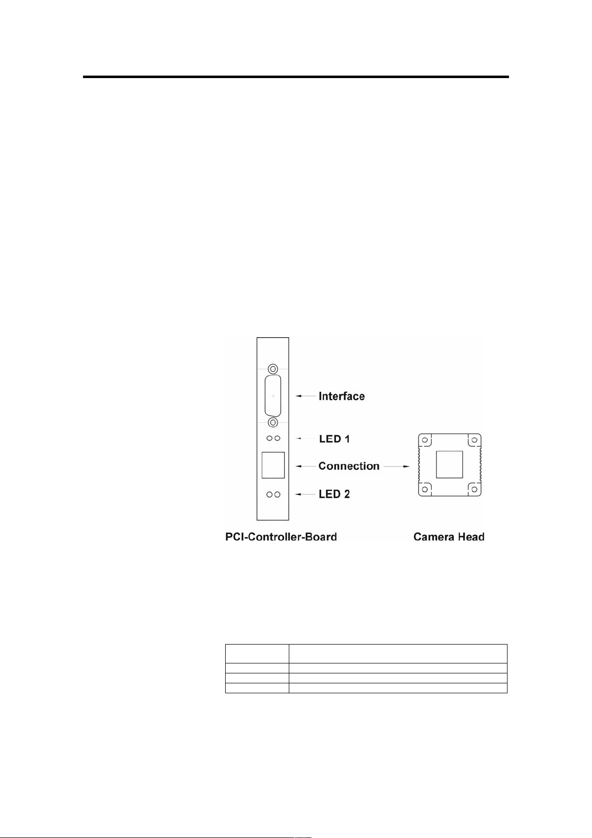
Standard and Compact PCI-Board
The front plates and connectors of the Standard and Compact
PCI-Boards are identical.
Frontplatten und Steckeranordnungen.
!PCO 2006
pixelfly
Interface 2 is the connection between camera head and PCIBoard.
The camera can be controlled via Interface 1 (e.g. external triggering, Front-End Processor, ...)
The LEDs show the operating states as follows:
LED 1 (green) control display when connection between camera head and
PCI-Board is ok
LED 1 (red) control display at data transfer
LED 2 (green) Power-On (blinking)
LED 2 (red) control display at external trigger input

12 1. Installation and Powering Up
Lens Mount pixelfly has a standard C-Mount with a back focal length of
17.52mm (Distance between front edge of C-Mount and CCDsensor).
Standard C-Mount lenses or other lenses with their respective
C-Mount adapter (e.g. photo camera lenses) can be used. The
maximum screw-in depth of a lens (or adapter) is 9.5mm.
Deeper screwing in could destroy the protecting window of the
camera (no warranty!).
The VGA and HiRes sensors have a 1/2“ format, the SVGA and
QE sensors a 2/3“. We recommend to use for all pixelfly Versions a 2/3“ or 1“ compatible lens. Cameras with high resolution
sensor should preferably be equipped with a high quality lens to
take advantage of the high resolution.
The cameras can be equipped optionally with a filter. This filter
will be placed at the C-Mount ring. In this case the maximum
screw-in depth is only 6mm instead of the 9.5mm.
Insert Filters Filters can be set in front of the CCD. You have to use a 24 mm
diameter filter.
In the C-mount screw there is a ring which can be screwed out.
Now the filter can be placed and the ring must be screwed in
again.
1.5 Powering Up
Check the following points:
" PCI-Board properly mounted
" Connection between camera and PCI-Board
" Lens mounted
Now start the program „CamWare“ from the directory
Programme – Digital Camera ToolBox.
For detailed information to CamWare please see the separate
manual ‚CamWare’.
!PCO 2006
pixelfly
 Loading...