

pco.
pco.
user manual
edge 4.2 bi
pco.edge 4.2 bi UV
PCO asks you to carefully read this manual before using the
pco.edge camera system and follow the instructions.
In case of any questions or comments, contact us at PCO.
telephone +49 (0) 9441 2005 50
fax +49 (0) 9441 2005 20
email info@pco.de
postal address PCO AG
Donaupark 11
93309 Kelheim, Germany
The cover photo shows an exemplary PCO camera system.
The lens is sold separately.
Copyright © 2019 PCO AG (called PCO in the following text), Kelheim,
Germany. All rights reserved. PCO assumes no responsibility for errors or
omissions in these materials. These materials are provided as is without
warranty of any kind, either expressed or implied, including but not limited to,
the implied warranties of merchantability, fitness for a particular purpose, or
non-infringement. PCO further does not warrant the accuracy or
completeness of the information, text, graphics, links or other items
contained within these materials. PCO shall not be liable for any special,
indirect, incidental, or consequential damages, including without limitation,
lost revenues or lost profits, which may result from the use of these materials.
The information is subject to change without notice and does not represent a
commitment on the part of PCO in the future. PCO hereby authorizes you to
copy documents for non – commercial use within your organization only. In
consideration of this authorization, you agree that any copy of these
documents, which you make, shall retain all copyright and other proprietary
notices contained herein. Each individual document published by PCO may
contain other proprietary notices and copyright information relating to that
individual document. Nothing contained herein shall be construed as
conferring by implication or otherwise any license or right under any patent or
trademark of PCO or any third party. Except as expressly provided, above
nothing contained herein shall be construed as conferring any license or right
under any PCO copyright. Note that any product, process, or technology in
this document may be the subject of other intellectual property rights
reserved by PCO, and may not be licensed hereunder.
Released: July 2019 © PCO AG
pco.edge 4.2 bi (UV) user manual V1.00 © PCO AG, Germany

TABLE OF CONTENTS
TOP
TABLE OF CONTENTS
1. INTRODUCTION 4
1.1 INTENDED USE 4
1.2 CONVENTIONS 4
2. SAFETY INSTRUCTIONS 5
3. SYSTEM COMPONENTS 6
4. INSTALLATION 7
4.1 DRIVER 7
4.2 CAMWARE SOFTWARE 8
5. QUICK START 9
5.1 PREPARATION 9
5.2 START 9
5.3 FIRST IMAGE 10
6. ROLLING SHUTTER 11
7. CAMWARE 4 SOFTWARE 15
7.1 HARDWARE IO CONTROL 15
APPENDIX 17
A1 TECHNICAL DATA 18
A1.1 DATA SHEET 18
A1.2 MECHANICAL DIMENSIONS 19
A1.3 REAR PANEL 20
A2 HARDWARE MOUNTING 21
A2.1 USB CARD INSTALLATION 21
A2.2 CABLE MOUNTING 22
A2.3 DIRECT CAMERA MOUNTING 23
A3 F-MOUNT ADAPTER 24
A3.1 PCO F-MOUNT ADAPTER 24
A3.2 CHANGE FROM F-MOUNT TO C-MOUNT 25
A4 WATER COOLING OPTION PCO.AQUAMATIC II 26
A4.1 SYSTEM COMPONENTS 26
A4.2 FIRST TIME INSTALLATION 27
A4.3 OPERATION 28
A4.4 DIMENSIONS 29
A4.5 YOUR OWN COOLING SYSTEM 29
A5 CUSTOMER SERVICE 30
A5.1 SERVICE 30
A5.2 MAINTENANCE 30
A5.3 RECYCLING 30
A5.4 TROUBLE SHOOTING 31
A6 INDEX 32
ABOUT PCO 33
3

bold italics
Terms that can be found in the software pco.camware
Features
Heading within a chapter
A1.3
Bold chapter: hyperlink to a chapter
Numbers that help to find functions quickly
Notes that must be observed
1
1
1. INTRODUCTION
Advantages of the pco.edge 4.2 bi (UV)
Features
Innovations aren’t always about having that one big new idea. Unique
technology also comes from evolution, combining existing and new
technology. When our tried and trusted pco.edge series pools forces
with modern back illuminated (bi) sensor technology, the result is our
pco.edge 4.2 bi (UV).
The adjustable cooling system allows the use of air or water to cool
the sensor down to -25 °C. At this temperature, the dark current is
reduced to 0.2 e-/pixel/s.
According to your application you can choose an input window
specialized either for the UV or VIS range. High resolution and 6.5 x
6.5 μm² pixel size guarantees high-quality images with quantum
efficiency up to 95 %. The pco.edge 4.2 bi (UV) incorporates a
powerful USB 3.1 interface complementing its performance.
Main Features
1.1 INTENDED USE
1.2 CONVENTIONS
• Resolution: 2048 x 2048 pixels
• Superior quantum efficiency up to 95 %
• 26667:1 dynamic range
• lowest dark current (typ.) 0.2 e-/pixel/s
• USB 3.1 interface
This camera system is designed for use by technicians, engineers
and scientists. It is a scientific measuring instrument, which provides
images. The camera may only be used according to the instructions
of this manual. The disclosures and operating conditions in these
operating instructions installation must be respected. Unauthorized
modifications and changes of the device are forbidden for safety
reasons.
The following typographic conventions are used in this manual:
4
2 SAFETY
NOTICE
NOTICE
NOTICE
NOTICE
NOTICE
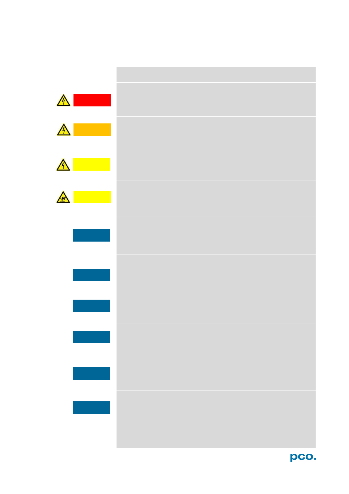
DANGER
WARNING
CAUTION
CAUTION
2. SAFETY INSTRUCTIONS
Read the safety instructions completely and follow them strictly.
DAMAGED POWER CABLE OR POWER PLUG
Danger to life due to electric shock.
Each time the camera is used, check the power cable for
damage.
ELECTRIC SHOCK WARNING DUE TO VOLTAGE PARTS INSIDE
Risk of injury due to electric shock.
Never slide any items through slits or holes into the camera.
MOISTURE
Risk of injury due to electric shock if moisture enters the camera.
To avoid the risk of water condensation, protect the camera
against extreme changes of ambient temperature.
TRIPPING HAZARD
Risk of injury from tripping over loose cables.
Never position the cable in a way that it could become a
tripping hazard.
HUMIDITY, DUST OR RADIATION
NOTICE
Humidity, dust or X-rays could damage the camera.
Never operate the camera in humid or dusty environments
or in places with high levels of x-ray radiation.
JOLT & VIBRATION
To avoid damaging the camera it must be firmly mounted and
protected against strong shocks or vibrations.
Use the camera's mounting threads to secure it.
LENS MOUNTING
Screw in the lens gently to avoid thread damage.
To protect the lens connector thread from damage, use
minimal force when attaching a lens to the camera.
LIQUIDS DAMAGE CAMERA
If liquids have penetrated the device.
Switch the camera off immediately, detach it from power and
contact PCO's customer support.
DAMAGED CAMERA HOUSING
If the camera has been dropped or the camera body is damaged.
Switch the camera off immediately, detach it from power and
contact PCO's customer support.
IF CAMERA IS NOT WORKING PROPERLY
In case all actions following this manual to get the camera working
properly were unsuccessful.
Switch the camera off immediately, detach it from power and
contact PCO's customer support.
INSTRUCTIONS
5
• Power connector
Mounting Thread
USB 3.1 Cable
Power Supply & Power Cord
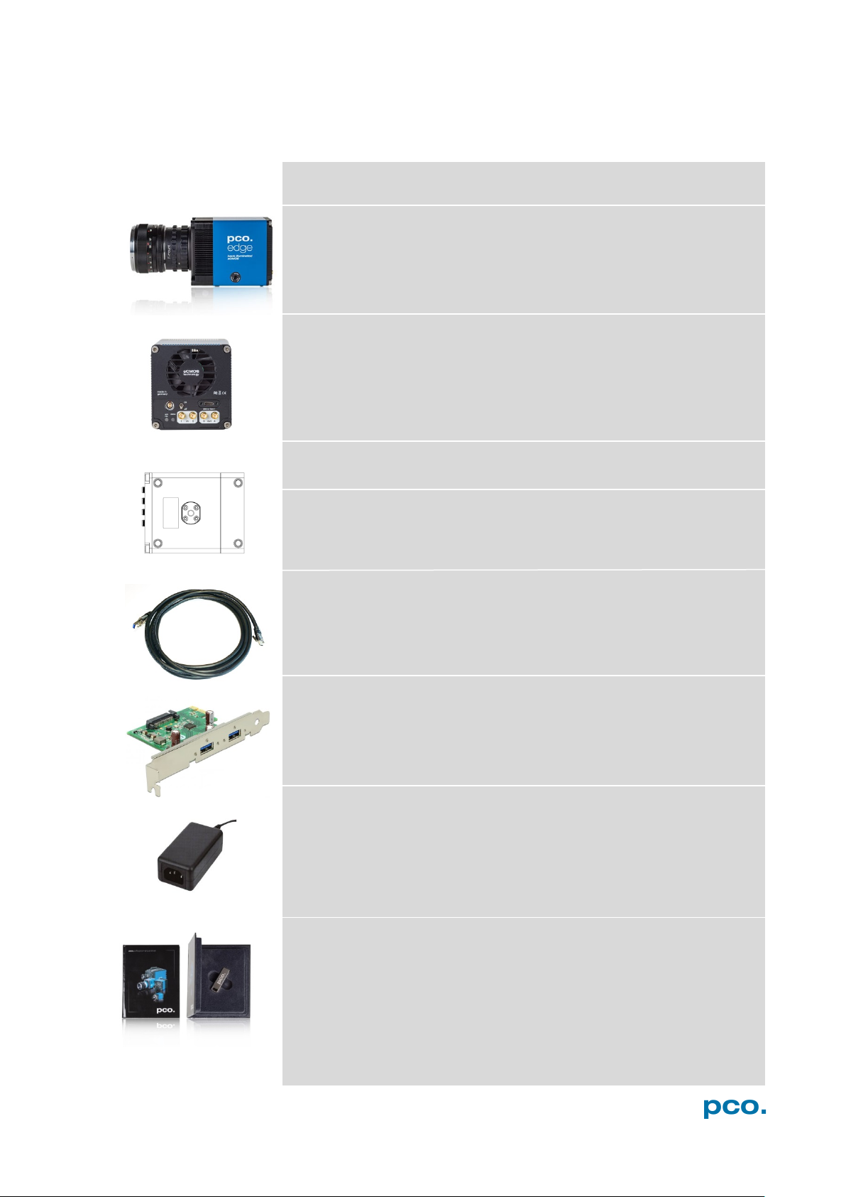
3. SYSTEM COMPONENTS
The camera system includes the following parts.
Camera
• F-mount / C-mount optical connection
• For standard C-mount / F-mount lenses and adapters
Rear Panel
• USB 3.1 Type C connector
• LED indicates camera status (see A1.3)
• SMA connectors
Serial Number Tag
• 1x 1/4"- 20 UNC
• USB Type A / USB Type C screwable cable
• Length 3 m
USB 3.0 / 3.1 Gen1 Interface Card
• 2x USB Type A socket
• PCI Express x1 V2.0
• Output: 24 VDC / 36W / 1.5A
• Connector: Lemo FGG.0B
• Voltage input: 115 VAC - 230 VAC; IEC 60320 C14 plug
• Power cord IEC 60320 C13
Digital Camera Tools (USB flash drive content)
• pco.camware: software for camera control & image acquisition
• Camera driver & tools
• Software Development Kit (SDK) & demo programs in C and C++
6
4 INSTALLATION
• Intel® Core™ i7
• Full-HD resolution display
• RAM > 8 GB DDR3
• USB 3.1 Gen1
• Windows 7 or higher
3
4
3 4 1
2
1
2
4. INSTALLATION
You find all necessary files on the accompanying USB flash drive.
You may also download the latest versions of our software, camera
driver and third party software drivers from our Website
(www.pco.de).
Minimum System Requirements:
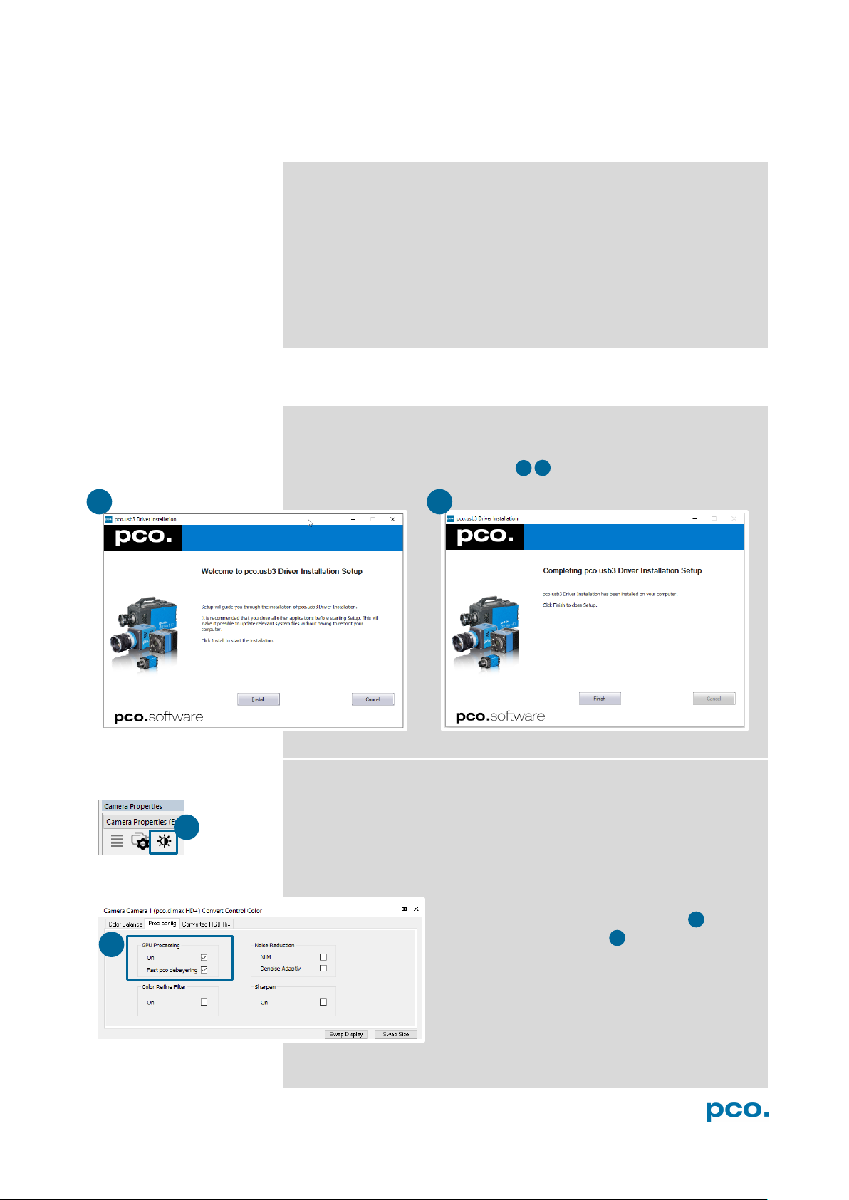
4.1 DRIVER
Install PCO USB 3.0/3.1 Driver
Always install the latest USB driver version. After these two screens
the driver is completely installed.
NVIDIA Cuda Driver
Only relevant if an NVIDIA graphics card is used! GPU Processing is
only working with NVIDIA graphics cards.
Update your NVIDIA driver for pco.camware. In case of an old driver
version GPU Processing is not working. Therefore image processing
is slow.
Check if GPU Processing is activated by having
a look into the Proc config settings in the
Convert Control window (see pco.camware
manual).
If GPU Processing is disabled and greyed out,
update your NVIDIA driver.
7
1 2 3
4
1
1
2
3
4
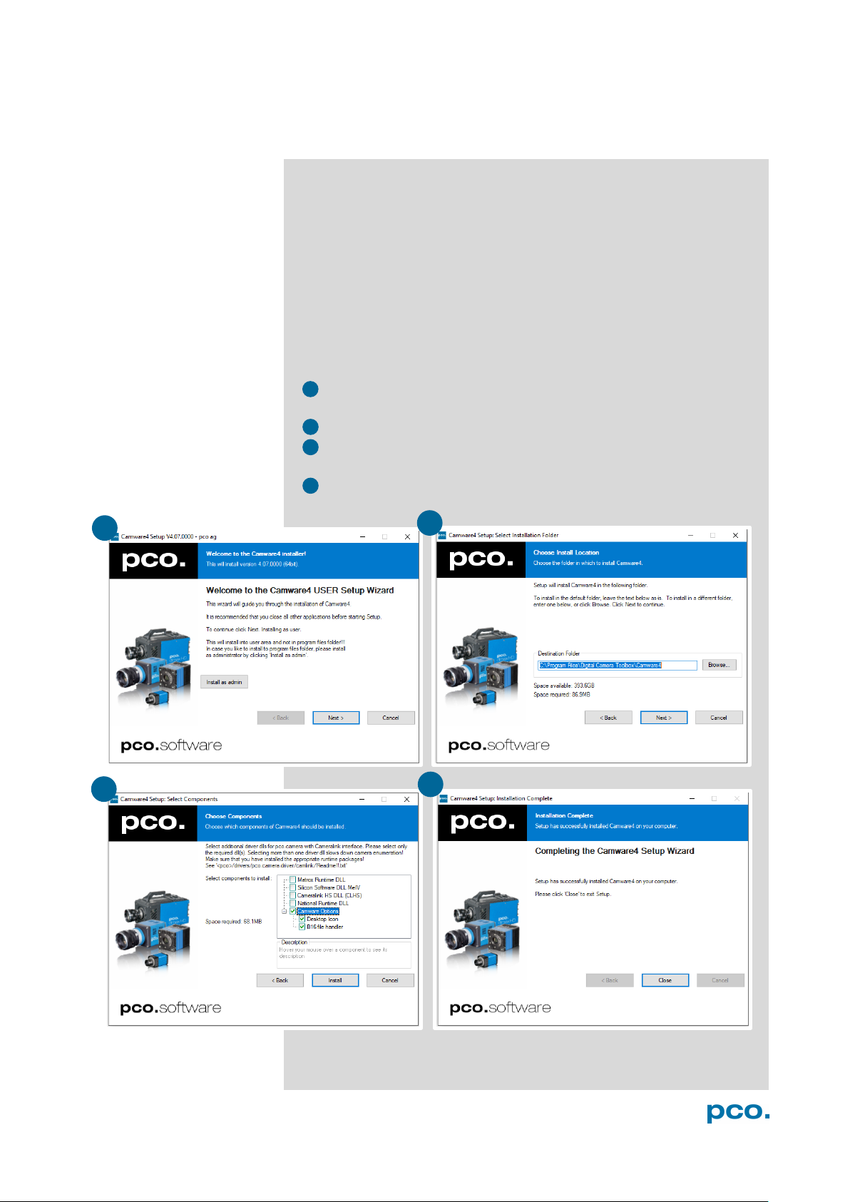
4.2 CAMWARE SOFTWARE
The pco.camware application software enables to control every
camera parameter or setting. Images can be displayed on a monitor
and may be downloaded and stored. The USB flash drive contains
the installation files for the software for latest Windows operating
systems in 32 & 64 bit.
After a successful installation, you find the program file Digital
Camera Toolbox in your program directory and a pco.camware 32 /
64 button on your desktop.
To uninstall the pco.camware program, use the software feature
under Windows’ system control.
Follow the Installation Wizard
• Install as admin to install to program folder, otherwise it is
installed only to user folder
• Choose install directory
• Choose components: select additional drivers (not recommended
for pco.edge 4.2 bi (UV))
• After the next two screens installation is complete
8
5 QUICK
5. QUICK START
5.1 PREPARATION
START
In order to get familiar with your new camera and software it might be
helpful, if you first aim at an object that is easy to focus and that can
be seen at standard light conditions.
• Computer is turned on
• Installation is finished (see chapter 4)
• An appropriate lens is attached (remove cap) or the camera is
attached properly to the microscope, spectrograph or other
scientific device
• Camera is connected to the PC
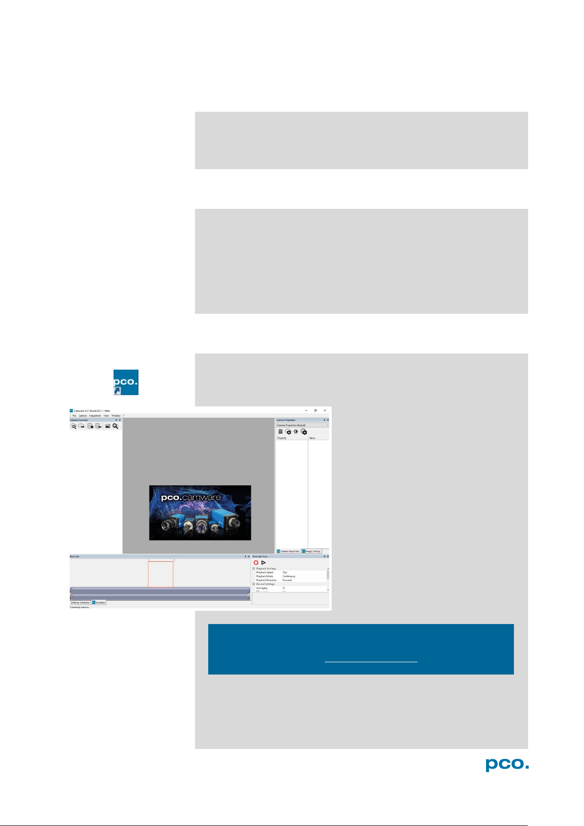
5.2 START
Start pco.camware and the graphical user interface starts up:
NOTE
Always install latest pco.camware version to be able to use full
function of your camera (www.pco.de/support
).
9

7
6
2
2
4 5 6
7
3
4 5 1
1
3
5.3 FIRST IMAGE
Follow the Instructions
• pco.camware must be started
• A View Window is shown automatically or open a new one
• Start Live Preview
• Right-click in the view window & apply Continuous Auto Range
• You may adjust Exposure time , aperture and focus of the
mounted lens
• Now you should clearly see the object in the window
To change Exposure time (e.g. the
image is still either too dark or too
bright) and to record and save
images, see pco.camware manual
for detailed information.
NOTE
Live preview: useful for fast and easy camera adjustment and
focusing.
10

6 ROLLING
pco.edge 4.2 bi (UV)
NOTE
exposure and
delay time can be
adjusted in steps of
6. ROLLING SHUTTER
The pco.edge 4.2 bi (UV) uses the rolling shutter mode. In this mode
the pixel reset and exposure start is carried out line by line. Each line
has the same exposure time, but a different start and end of
exposure. Within one line, the exposure starts simultaneously for all
pixels.
The exposure time of each line starts with the corresponding reset of
the line. Then after a predefined time (exposure time), the exposure is
stopped. The light induced accumulated charge carriers of the pixels
in a line are recorded into memory in a low noise (readout) mode. This
way the content of the pixels is assembled in the memory to form the
complete image.
The diagram shows different signal timing settings (see chapter 7.1).
During Show common time of ‘All Lines’ the image sensor is
completely exposed to light. The labels Show time of ‘First Line’
and ‘Last Line’ are the setting for the first / last exposed line and
Show overall time of ‘All Lines’ for the entire exposure period.
There are two different timing cases for rolling shutter mode, which
are explained on the following pages:
• exposure time > sensor readout time
• exposure time < sensor readout time
Rolling Shutter General Timing Diagram
SHUTTER
The
one line time.
Timing
Camera Exposure time Delay time Line time
USB 3.1
11
10 μs … 20 s 0 … 5 s 12.174 μs

Exposure time > Sensor frame readout time
In case the required exposure time is longer than the frame readout
time, the image sensor is completely exposed to light for some time
(Show common time of ‘All Lines’ also see General Timing
Diagram). In case of a triggered flash illumination, this would be the
best moment to illuminate the image sensor. The hardware signal for
the time Show common time of ‘All Lines’ is available on connector
#4 (see 7.1).
This is an example timing diagram for Trigger Mode Auto
Sequence, SMA explanation see 7.1
Δt = 4.4 μs
12

6 ROLLING
SHUTTER
exposure stop & readout
reset & exposure start
band of simultaneous exposures
Exposure time < Sensor frame readout time
In case the required exposure time is shorter than the frame readout
time, the image is readout through an exposure band moving from
the top to the bottom of the sensor.
For example:
How can you calculate the band of simultaneous exposure lines at an
exposure time of 100μs (@ full resolution)?
Exposure time
Line time
This is an example timing diagram for Trigger Mode Auto
Sequence, SMA explanation see 7.1
= Number of simultaneous exposure lines
100 µs
12.174 µ
= 8,2 → 8 lines
13

t
Jitter
≤
t
Fixed system delay of rising edge
2x line time1
t
Programmable delay time
0 μs … 5 s
NOTE
can be a
The jitter t
jit
maximum of one line
time.
Details for External Exposure Start and External Exposure Control
The detailed timing for external trigger includes system delay times,
an adjustable additional delay time, and the jitter. Explanation for all
Trigger Modes see pco.camware manual.
Name Explanation Value
jit
rsys
delay
1
line time = 12.174 μs
For optimized synchronization (minimized jitter time) use the falling
edge of the line signal at the Status Expos output SMA #4 (see 7.1).
System time t
is depending on your camera settings and can be
rsys
read out from your camera, for further information see SDK manual
function PCO_GetImageTiming.
1 line time1
14

7 CAMWARE
1
2 3 4
1
2 3 4
1 2 3
4
7. CAMWARE SOFTWARE
This chapter contains only camera-specific additions to the
pco.camware manual. All main functions and explanations can be
found in the pco.camware manual.
7.1 HARDWARE IO CONTROL
Change setting are done via drop-down menu.
Exposure Trigger
If checked, a signal for External Exposure Start Trigger Mode
is accepted at the Exposure Trigger SMA input #1.
Exposure Trigger: On; Off
Signal Polarity: Rising; Falling
Aquire Enable
SOFTWARE
If checked, a signal for Acquire Mode is accepted at the Acquire
Enable SMA input #2.
Acquire Enable: On; Off
Signal Polarity: High; Low
Status Busy
If checked on, a signal indicating busy status is provided at the
Status Busy output. Once an acceptable trigger edge is received,
‘busy’ goes to status high. As soon as ‘busy’ goes low again, a new
trigger edge is accepted.
Status Busy: On; Off
Signal Polarity: High; Low
Status Expos / Status Line
If checked, a signal indicating exposure or line status is given at the
status output. Status Expos indicates the actual exposure window
for one frame. Use the falling edge of the Status Line signal for
optimized synchronization.
Detailed explanation for Signal timing see next page!
Select IO Signal: Status Expos; Status Line
Signal timing: Show time of ‘First Line’; Show common time of
‘All lines’; Show time of ‘Last line’; Show overall time of ‘All lines’
Status Expos: On; Off
Signal Polarity: High; Low
15

1 2 4
3 1 2
4
3
1
2
3
4
Enabling and Polarity of IO Signals
The polarity of the input and output signals indicating their active
states is selectable (positive or negative logic).
The polarity of level-sensitive signals can be set to High (positive
logic) or Low (negative logic).
The polarity of edge-sensitive signals can be set to Rising (positive
logic) or Falling (negative logic).
Detailed Explanation for Status Expos SMA #4 Signal Timing
Setting in pco.camware:
There are four different signal types selectable. The example timing
diagram shows all four different possibilities:
• Shows the exposure time of the first line
• Shows when all sensor lines are exposed
• Shows the exposure time of the last line
• Shows if any sensor line is integrating
16

APPENDIX
APPENDIX
A1 TECHNICAL DATA 18
A1.1 DATA SHEET 18
A1.2 MECHANICAL DIMENSIONS 19
A1.3 REAR PANEL 20
A2 HARDWARE MOUNTING 21
A2.1 USB CARD INSTALLATION 21
A2.2 CABLE MOUNTING 22
A2.3 DIRECT CAMERA MOUNTING 23
A3 F-MOUNT ADAPTER 24
A3.1 PCO F-MOUNT ADAPTER 24
A3.2 CHANGE FROM F-MOUNT TO C-MOUNT 25
A4 WATER COOLING OPTION PCO.AQUAMATIC II 26
A4.1 SYSTEM COMPONENTS 26
A4.2 FIRST TIME INSTALLATION 27
A4.3 OPERATION 28
A4.4 DIMENSIONS 29
A4.5 YOUR OWN COOLING SYSTEM 29
A5 CUSTOMER SERVICE 30
A5.1 SERVICE 30
A5.2 MAINTENANCE 30
A5.3 RECYCLING 30
A5.4 TROUBLE SHOOTING 31
A6 INDEX 32
ABOUT PCO 33
17

Image sensor
pco.edge 4.2 bi (UV)
Type of sensor
Customized sCMOS
Resolution (h x v)
2048 x 2048 pixel
Pixel size (h x v)
6.5 μm x 6.5 μm
Sensor format / diagonal
13.3 x 13.3 mm / 18.8 mm
Shutter mode
Rolling Shutter (RS)
MTF
76.9 lp/mm (theoretical)
Camera
Frame rate
40 fps @ full resolution
Exposure / shutter time
10 μs ... 20 s
Dynamic range A/D
16 bit
Binning (h x v)
1x1 ... 4x4
Cooling method
Adjustable: from -25°C to +20°C
Calibration setpoint: -10°C
Trigger input signals
Frame Trigger, Acquire (SMA connectors)
Trigger output signals
Exposure, Busy (SMA connectors)
Data interface
USB 3.1 Gen1
Timestamp
In image (1 μs resolution)
General
Power delivery
Power over USB 3.1 Gen1 Type-C and power
connector (24 VDC +/- 10%)
Power consumption
Typ. 4.5 W over USB 3.1 Gen 1 and
Weight
920 g
Operating temperature
+10°C ... +40°C
Operating humidity range
10% ... 80% (non-condensing)
Storing temperature
range
-10°C ... +60°C
Optical interface
F-mount, C-mount
CE / FCC certified
Yes
ROI step sizes
Horizontal steps
32 pixel steps
Vertical steps
8 pixel steps
Minimum ROI
64 x 16 pixels
A1 TECHNICAL DATA
A1.1 DATA SHEET
Peltier with forced air (fan) and water cooling.
typ. 10.0 W (max. 22.0 W) over power
connector
Subject to change, refer to current data sheet available on our website.
18

A1 TECHNICAL DATA
NOTE
focal distance:
A1.2 MECHANICAL DIMENSIONS
C-Mount flange
17.52 mm
All dimensions given in millimeter.
2D and 3D technical drawings are available on our website
3D step files and further technical drawings are available on request.
19

Color
Description
Red / green continuous
Camera is booting
Green
Camera is ready for operation
Orange continuous
Arm camera / rec state off
Orange blinking
Recording on
Red continuous
Error
Input (1=Exposure Trigger; 2=Acquire Enable)
Type
Digital
Level
3.3 V LVTTL (5 V tolerant)
Coupling
DC
Impedance
1 kΩ
Slew rate
> 1 V/ms
Output (3=Status Busy; 4=Status Expos)
Type
Digital
Level
3.3 V LVTTL
Coupling
DC
LEMO socket ECG.0B.302.CLV
Pin1
Ground
Pin2
VCC 24 V DC (+10%)
3 1 4
2
1
4
3
2
5
6
Pin1
Pin2
5
6
A1.3 REAR PANEL
Status LEDs
(LED1: green / red; LED 2: orange)
Interface Connector
USB 3.1 plug Type-C screwable;
Power delivery for the camera over USB cable
SMA Inputs
(see chapter 7)
SMA Outputs
(see chapter 7)
Power Input
Appropiate Lemo plug: FGG.0B.302.CLAD52Z
Power Switch
20

A2 HARDWARE MOUNTING
1
1
3
2
2
3
WARNING
NOTE
operation, each
edge 4.2 bi
own USB host
A2 HARDWARE MOUNTING
Instructions how to mount the pco.edge 4.2 bi (UV) camera system.
A2.1 USB CARD INSTALLATION
An external USB 3.0 / 3.1 Gen1 host controller card comes along with
to each pco.edge 4.2 bi (UV) camera.
Hardware Installation
First shut down your computer and install the USB 3.0 / 3.1 Gen1
host controller card. Hardware installation must be performed by a
technician, because high voltages can occur on the device.
ELECTRIC SHOCK WARNING DUE TO VOLTAGE PARTS INSIDE
Risk of injury due to electrical shock.
Always pull the main plug before opening the computer.
Driver Installation Instructions
In multi-camera
pco.
camera needs its
controller card.
• If your current OS is Win 7 / 8 and the User Account Control is
• Within the provided installation files USB_HBA, open the folder
U3X4-PCIE4XE101, U3X4-PCIE1XE101, U3-PCIE1XG202.
• Open the subfolder Driver and run RENESAS-USB3-Host-Driver-
30230-setup.exe.
enabled, a dialog prompts whether you wish to start the setup:
accept with Yes.
• At first the installation is prepared.
• Secondly the software components are copied automatically.
• Finally the installation is completed and the Delock USB 3.0 / 3.1
Gen1 extension card can be used.
21

NOTICE
A2.2 CABLE MOUNTING
In order to ensure a proper function of the pco.edge 4.2 bi (UV), it is
necessary to secure the USB cable by the fixing screws.
The accompanying USB cable is screwable on both ends of the
cable.
The maximum torque for the screws is 0.1 Nm.
Screw Connection to the Camera (recommended)
• The screw threads of the camera are very sensitive due to the
• Plug the USB cable into the camera.
• Then attach the fittings to the threads by hand.
Screw Connection to the Computer (optional)
small size.
• Attach the cable to the USB card in the same way.
22

A2 HARDWARE MOUNTING
3 1 2
3 4 4 1 2
NOTICE
A2.3 DIRECT CAMERA MOUNTING
The hardware design allows to mount the camera very close to an
optical setup (e.g. a microscope) without F- or C-mount adapter but
with the help of a rubber ring.
This allows to reduce the distance from the focal plane of the sensor
to the adaption plate to only 6.18 mm.
Contact us, if you need the rubber ring. The ring is not included in the
standard package of the camera:
O-ring D 55 x 1.5 material number: 10305100011
The rubber ring is essential for this direct adaption, as it is necessary
to block parasitic light.
Mounting Steps
First, the adapter containing the lens mount must be removed.
Completely unscrew the four cylinder head screws M4 x 8 and
remove the adapter.
As second step, place the rubber ring in the intended recess of the
camera.
Finally screw the camera to your optical setup by using the four M4
screw sockets .
Always make sure that the O-ring does not slip out of the recess!
23

Type 35mm F-Mount
• A012: SP 15-30mm F/2.8 Di VC USD
• F017: SP 90mm F/2.8 Di MACRO 1:1 VC USD
Type APS-C(H) F-Mount
•
• G005: SP AF 60mm F/2.0 Di II LD [IF] Macro 1:1
A3 F-MOUNT ADAPTER
A3.1 PCO F-MOUNT ADAPTER
Matching Lenses with Automatic Diaphragm
PCO's proprietary F-mount adapter for lenses
with automatic diaphragm. Sets manually the
lens aperture by turning the ring on the
adapter.
F-mount lenses
without automatic
diaphragm can be
fastened to the
camera's mount but
the aperture not
changed.
Adjust Back Focal Length
To adjust the back focal length (e.g. you
cannot focus to infinity or to the minimum
object distance of your lens), proceed as
follows:
Set the focus of your lens to infinity. Look at
an object in infinity and generate a sharp
image by turning the adapter. Use the
rearmost ring to fix the setting.
Nikon: all Nikkor lenses of type D and type G (not for type E, this one
is only electronic).
Zeiss: all ZEISS ZF.2 lenses (Otus, Milvus, Interlock, Distagon,
Planar).
Sigma: only lenses, which already have a manual diaphragm ring; all
other lenses have an aperture control lever, which does not spring
back, if you turn the aperture ring at the adapter.
Tamron: only some lenses provide automatic diaphragm (no
particular lens family):
• A007: SP 24-70mm F/2.8 Di VC USD
• A009: SP 70-200mm F/2.8 Di VC USD
• A011: SP 150-600mm F/5-6.3 Di VC USD
• F012: SP 35mm F/1.8 Di VC USD
• F013: SP 45mm F/1.8 Di VC USD
B001: SP AF 10-24mm F/3.5-4.5 Di II LD Aspherical [IF]
• B005: SP AF 17-50mm F/2.8 XR Di II VC LD Aspherical [IF]
24

A3 F-MOUNT ADAPTER
1
1
2 2 2 4 4
3
3
A3.2 CHANGE FROM F-MOUNT TO C-MOUNT
How to change the optical input from F-mount to C-mount.
MECHANICAL DAMAGE OF THE C-MOUNT RING
NOTICE
Tightening the hexagon socket setscrews too tight will permanently
damage the C-mount ring.
Use a torque wrench and select a maximum torque of 1 Nm
to tighten the hexagon socket setscrews.
Step 1: Remove F-mount adapter
Turn the black lock ring counterclockwise to loosen the F-mount
adapter and then unscrew it.
Step 2: Insert C-mount ring
Carefully screw the C-mount ring clockwise. The two hexagon
setscrews must be visible on the outside.
Step 3: Adjust flange focal distance
In order to reach the standard support dimension of C-mount (17.526
mm), screw in the C-mount ring so far that it protrudes outwards a
distance of 1.8 mm .
For fine adjustment use a suitable lens with large aperture.
Step 4: Fix the C-mount ring
To fix the C-mount ring, tighten both hexagon setscrews (1.5 mm
hex key) to a maximum torque of 1 Nm.
Limitations of C-mount Lenses
Keep in mind that C-mount lenses could cause shadings at the edges
of big sized sensors. Most C-mount lenses are able to illuminate a
maximum image circle of 11 mm (2/3”), 16 mm (1”) or 22 mm (4/3”)
diameter only. The pco.edge bi has a sensor diagonal of 18.8 mm, it
follows that you have to use the ROI function for a shade less image
while using the C-mount adapter with the two smaller C-mount
diameters.
25

Description
pco.aquamatic
connection tube 5m PVC 3541-01 PCO (Colder NS212 fittings)
power supply (1.2m cable length)
power cable
camera cable 5m (FGG-RG58-NC3MX)
Innovatec Protect IP 1l
NOTE
1
2
6
1 2 3 4 5
6
4
3
5
A4 WATER COOLING OPTION PCO.AQUAMATIC II
This is the re-cooling system for pco.edge cameras with watercooling.
A4.1 SYSTEM COMPONENTS
Normally no maintenance and almost no care is required. Only the
coolant’s level of the reservoir (water tank) should be checked from
time to time.
Only use Innovatec Protect IP for the pco.aquamatic! Do not use or
add any other coolant or normal water! If you need to add cooling
liquid in order to maintain the tank level, contact PCO for additional
supply.
The coolant will turn yellow after some hours of operation. This is
normal and no sign of wear or malfunction. The optimum pH-value is
between 8 and 9 (check this value if you are concerned about the
coolant’s quality).
The recommended service interval for the change of the coolant is
four years.
26

A4 WATER COOLING OPTION PCO.AQUAMATIC II
1
1 2 3 4 5
6
2
3
4
5
NOTE
The hose connectors are waterproof in not connected state.
system.
6
A4.2 FIRST TIME INSTALLATION
Take care to place the unit on a flat and firm surface. Do not cover
the cooling vents of the unit. Ensure free airflow around the
pco.aquamatic for maximum cooling performance. All tubes and
power cords need to run kink-free.
Before installation of the unit carefully read the Innovatek Protect
IP safety datasheet (see Innovatek Website
Follow Steps 1 – 6
1. Connect tubes to cooling unit and camera. The two arrows on the
housing of the cooling unit only indicate flow direction. Either
connection of the camera can be used for in or out.
2. Connect to power.
3. Open tank cover.
4. Turn power switch on (I).
• Slowly fill in the coolant while the unit is running. Refill as needed
to keep the level.
• While the cooling liquid flows back to the tank make sure all air
gets out of the system – this takes a few minutes (move hoses if
necessary).
).
outlet flow
inlet flow
The cooling liquid tank is full when liquid level is approximately 1-2
cm from the top of the tank. The integrated pump only works when
the pump chamber is completely filled. To ensure this Move hoses or
remove air by evacuating. Tank capacity is approximately 500 ml.
After steps 1 – 6 are completed successfully the system is ready for
operation.
Maybe they lose one drop of cooling liquid from time to time.
There is no need to empty the hoses while storing the camera
27

on
off
none
1Hz
flash
warning when temperature at 55 °C
(also if sensor is defect or missing)
2Hz
flash
fan speed
Temperature
Action
27°C
fan turns off
36°C
fan turns on
55°C
warning message
60°C
error message
NOTE
A4.3 OPERATION
First connect the power out of the cooling unit with the power in of
the pco.edge camera by using the PCO WAT camera cable.
The cooling unit provides two operation modes.
Operation Mode on: the cooling unit turns on and
provides permanently power to the camera. The
camera can be switchted on and off as needed.
Operation mode follow: the cooling unit turns on when
the camera is switched on and vice versa.
Error Codes
The coolant temperature sensor is located in the coolant tank.
If a warning level is passed, the Power LED blinks slowly and the
Error LED displays the error code. If a failure level is passed, the
Power LED blinks fast and the Error LED shows the error code.
Error / Failure
one short flash
one short flash failure when temperature at 60 °C
1Hz
flash
two short
flashes
(also if a high deviation of the standard value
is reached)
The camera has its own protection circuit and will shut down
Peltier cooling automatically when the electronics temperature
exceeds safety level. The camera itself will keep on running, but
sensor temperature will increase. (valid for air and water cooling!)
If the camera and the water cooler have a different power supply,
always first shut down camera and then the cooling system to
avoid damages.
28

A4 WATER COOLING OPTION PCO.AQUAMATIC II
A4.4 DIMENSIONS
All dimensions are given in millimeter.
Weight: 4kg (completely filled coolant tank)
A4.5 YOUR OWN COOLING SYSTEM
You are not obliged to purchase the pco.aquamatic system - you
may use your own water cooling device. A separate power supply will
be provided to every pco.edge camera with water connection. The
hardware of the pco.edge cameras with USB 3.1 interface is
designed to work with or without a water cooling system. A fan inside
the camera provides adequate cooling anyway.
In case you use an own water cooling system, make sure the liquid
you use to cool your camera is always ABOVE the dew point of the
ambient temperature. In order to avoid any occurance of
condensation, use a cooling liquid at room temperature.
• A liquid flow rate of 1–2 litres per minute is sufficient
• Always use Innovatec Protect IP cooling fluid or an equivalent
cooling fluid
29

NOTICE
CAUTION
NOTICE
NOTICE
NOTICE
A5 CUSTOMER SERVICE
A5.1 SERVICE
The camera is designed to operate with no need of special
adjustments or periodic inspections.
A5.2 MAINTENANCE
UNPLUG CAMERA BEFORE CLEANING
Risk of injury due to electric shock!
Unplug the camera from any power supply before cleaning it.
CLEANING
Use a soft, dry cloth for cleaning the camera.
Do not clean the input window unless it is absolutely
necessary (clean it with pressurized air).
Be careful and avoid scratches and damage to the input
window surface.
Do not use liquid cleaners or sprays.
LENS CLEANING
The lens is best cleaned with pressurized air or with liquid
cleaners such as pure alcohol or with special optical
cleaners that are available at high quality photo stores.
Use a cotton swab dipped in pure alcohol or optical cleaning
liquid and wipe only on the glass surface.
Do not get any cleaning liquid on the metallic parts such as
the lens thread, because tiny detached particles may scratch
the surface.
CLEANING LIQUIDS
Aggressive cleaning liquids can damage your camera.
Never use aggressive cleaning liquids such as gasoline,
acetone, spirits or nitro cleanser.
Every time the input window is cleaned, there is the
possibility of surface damage.
PROTECTIVE CAP
Always store the camera with the protective cap or with a lens
mounted to avoid dust and dirt on the input window.
A5.3 RECYCLING
If you want to dispose your camera, send it to PCO or take it to a
local recycling center.
The camera includes electronic devices, which can contain materials
harmful to the environment. These electronic devices must be
recycled.
30

A5 CUSTOMER SERVICE
1
1 2 2 3 3
A5.4 TROUBLE SHOOTING
Use pco.camware to create logfiles for the PCO support.
How to Create Logfiles
Enable Logging
? Help menu, select Logging and then Enable Logging
Open
The pco.camware will ask you to press YES to activate Logfiles after a
restart of the software.
Repeat Workflow
The workflow which produces the error must be repeated while
logging is enabled.
Support Mail (+Support File)
Open ? Help menu, select Support Mail (+Support File) and a
support file with all necessary files is created
The pco.camware opens a new email addressed to
support@pco.de
and send the mail to the PCO support.
Alternatively use the support form on our website:
http://www.pco.de/support/
To Speed up Your Request
, attach the Support File manually to this mail
and upload the support file.
Give us the following information:
• Describe your problem!
• Your application?
• Your camera:
o Type and version
o Serial number
• Your setup:
o Software version
o Operating system
o Processor and memory
o Graphics card
Firmware, Software and Driver Update
You will find all necessary software and drivers on the accompanying
USB storage device. For the latest versions check PCO website
31
.

Keyword
Chapter
Page
Camware installation
4.2
8
Cleaning
A5.1
30
Components camera system
3
6
Cuda Nvidia driver
4.1
7
Data sheet
A1.1
18
Dimensions
A1.2
19
Driver installation
4.1
7
F
A3
24
First Image
5.3
10
Hardware I/O Control
7.1
15
Input / Output possibilities
7.1
15
Installation 4 7
Live preview
5.3
10
Logfiles
A5.4
31
M
A5.2
30
Mounting
A2.2
22
R
A1.3
20
Recycling
A5.3
30
Rolling Shutter
6
11
Safety instructions
2
5
Support
A5
30
T
A5.4
31
USB card installation
A2.1
21
USB driver installation
4.1
7
Water Cooling
A4
26
NOTE:
always the starting
page of a chapter!
A6 INDEX
The mentioned page is
-Mount
aintenance
ear connections
rouble Shooting
32

ABOUT PCO
pco.
ABOUT PCO
pco.history
“PCO” stands for what we are: a Pioneer in Cameras and Optoelectronics. With 30 years of expert
knowledge and experience PCO has forged ahead to becoming a leading specialist and innovator
in digital imaging used in scientific and industrial applications such as life and physical science,
high-speed imaging and machine vision. However, the beginning of PCO’s story of success dates
back to the 1980s and a research project of the founder, Dr. Emil Ott, who was working at the
Technical University Munich for the Chair of Technical Electrophysics. While performing
measurements with intensified slow scan cameras, Dr. Ott realized that the existing standard did
not meet the sophisticated requirements of scientific applications – and so PCO came to life in
1987. With a small team of engineers Dr. Ott began to develop his first image intensified camera
followed by several variations on the original model, geared to overcoming all the existing flaws
and surpassing standards of the day. During these early years PCO developed a now well
established core of advance technologies used as the foundation to develop cutting edge
products.
In the early 1990s PCO expanded its business activities to the global market by successfully
establishing an international network of highly trained sales partners and customers. We entered
additional fields beyond traditional scientific research expanding the potential for our cameras’
applications in life science, automotive testing and even broadcasting. This step paved the way
for a wide range of innovative highlights:
As of 2017, PCO has three decades of technical know-how and expert knowledge in the
development and manufacturing of high-performing camera systems. In-house competence of all
significant technical disciplines and partnering with leading image sensors manufactures ensures
cutting edge sCMOS, CMOS and CCD technology for all PCO cameras.
pco.prospect
“If you want to do something special, particularly in the high end fields, you have to develop your
own image sensors. So we work with partner companies who develop tailored sensors made
especially for us. This is something we are doing continuously, so we’re already working on the
next generation of cameras that we will introduce in the coming years” – Dr. Emil Ott.
In PCO’s first 30 years, Dr. Emil Ott took a company that he started right after finishing university
and has built it into a major player in scientific and industrial cameras – and there’s plenty more to
come.
33

pco.
 Loading...