

Pco edge, edge GOLD, edge 4.2, edge 5.5, edge GOLD 4.2 User Manual
...
user manual
pco.edge
pco.edge GOLD
pco.edge 4.2
pco.edge 5.5
pco.edge GOLD 4.2
pco.edge GOLD 5.5
2
pco.edge User Manual V1.03 © PCO AG, Germany
In this manual you find instructions for the pco.edge scientific CMOS
(sCMOS) camera series.
Target Audience: The pco.edge is designed for use by technicians,
engineers and scientists.
In case of any questions or comments, please contact us at PCO.
telephone
+49 (0) 9441 2005 50
fax
+49 (0) 9441 2005 20
email
info@pco.de
postal address
PCO AG
Donaupark 11
93309 Kelheim, Germany
The cover photo shows exemplary PCO camera systems.
Lenses are sold separately.
Copyright © 2014 PCO AG (called PCO in the following text), Kelheim,
Germany. All rights reserved. PCO assumes no responsibility for errors
or omissions in these materials. These materials are provided "as is"
without warranty of any kind, either expressed or implied, including but
not limited to, the implied warranties of merchantability, fitness for a
particular purpose, or non-infringement. PCO further does not warrant
the accuracy or completeness of the information, text, graphics, links or
other items contained within these materials. PCO shall not be liable for
any special, indirect, incidental, or consequential damages, including
without limitation, lost revenues or lost profits, which may result from the
use of these materials. The information is subject to change without
notice and does not represent a commitment on the part of PCO in the
future. PCO hereby authorizes you to copy documents for noncommercial use within your organization only. In consideration of this
authorization, you agree that any copy of these documents, which you
make, shall retain all copyright and other proprietary notices contained
herein. Each individual document published by PCO may contain other
proprietary notices and copyright information relating to that individual
document. Nothing contained herein shall be construed as conferring by
implication or otherwise any license or right under any patent or
trademark of PCO or any third party. Except as expressly provided,
above nothing contained herein shall be construed as conferring any
license or right under any PCO copyright. Note that any product,
process, or technology in this document may be the subject of other
intellectual property rights reserved by PCO, and may not be licensed
hereunder.
Updated April 2014 © PCO AG

Table of Contents
pco.edge User Manual V1.03 © PCO AG, Germany
3
Table of Contents
1 Introduction ..................................................................... 5
2 Safety Instructions .......................................................... 7
3 System Components ....................................................... 8
Camera Head and Accessories
LEDs indicating Camera Status
4 Installation ....................................................................... 9
Computer Requirements
Frame Grabber (Camera Link) / USB 3.0 Installation
Software Installation (pco.camware)
5 Quick Start ..................................................................... 10
6 Camera Control for the pco.edge ................................ 11
6.1 The “Camera Control” window ........................................ 11
How to open the Camera Control window
Information Field (Displayed Camera Information)
6.2 The Timing tab ................................................................ 12
Trigger Modes explained
6.2.1 Rolling Shutter – Timing Details .................................. 14
6.2.2 Global Shutter – Timing Details ................................... 19
6.2.3 Global Reset – Timing Details ..................................... 22
6.3 The Sensor (Size) tab....................................................... 24
Binning
Region of Interest (ROI)
Sensor Format
6.4 The Sensor (Misc.) tab ..................................................... 25
Pixelclock
Spurious Noise Filter (“Blinkers”)
Conversion Factor
Electronics and Sensor Temperature Information
6.5 The Recording tab ........................................................... 26
Recorder Modes (sequence / ring buffer)
Acquire Mode (disable recording externally)
Sequence Trigger
Time Stamp
6.6 The In/Out Signals tab ..................................................... 29
Hardware Signal Input and Output

Table of Contents
4
pco.edge User Manual V1.03 © PCO AG, Germany
7 Camware Features ........................................................ 31
7.1 If no camera is connected ............................................... 31
Demo Mode Setup
7.2 Overview ......................................................................... 32
7.3 The File Menu .................................................................. 33
Open / Save / Export Files
Options: File / View Settings
Options: Toolbar, Logfiles
Direct Record to File (RAID operation)
7.4 The Camera Menu ........................................................... 37
Switch between Rolling Shutter, Global Shutter & Global Reset
Auto Exposure
7.5 The Acquisition Menu ...................................................... 38
Predefine number of images in RAM segment
Recorder Setting
7.6 The View Menu ................................................................ 39
Convert Control BW / Color
White Balance, Additional Filter, GPU Processing
7.7 The Window Menu .......................................................... 42
7.8 The Help Menu ................................................................ 42
Version Information
Support Links
7.9 The Local Menu ............................................................... 43
Right Mouse Button Features
7.10 Additional Features ......................................................... 45
Appendix
A1 Technical Data................................................................. 47
A2 Mechanical Dimensions .................................................. 52
A3 How to change optical input F-mount to C-mount ......... 54
A4 Image File Formats .......................................................... 55
A5 Service and Maintenance ................................................ 57
A6 Customer Service and Trouble Shooting ........................ 58
A7 Water Cooling Option (pco.aquamatic II) ........................ 59
A8 Image Data Flow (PC Recommendations)....................... 63
A9 ME4 Grabber Instructions ............................................... 65
A10 USB 3.0 Installation & Hardware Recommendations ...... 68
A11 Binning in CMOS Sensors ............................................... 71
About PCO .............................................................................. 72
1 Introduction
pco.edge User Manual V1.03 © PCO AG, Germany
5
1 Introduction
The new imaging standard.
Features
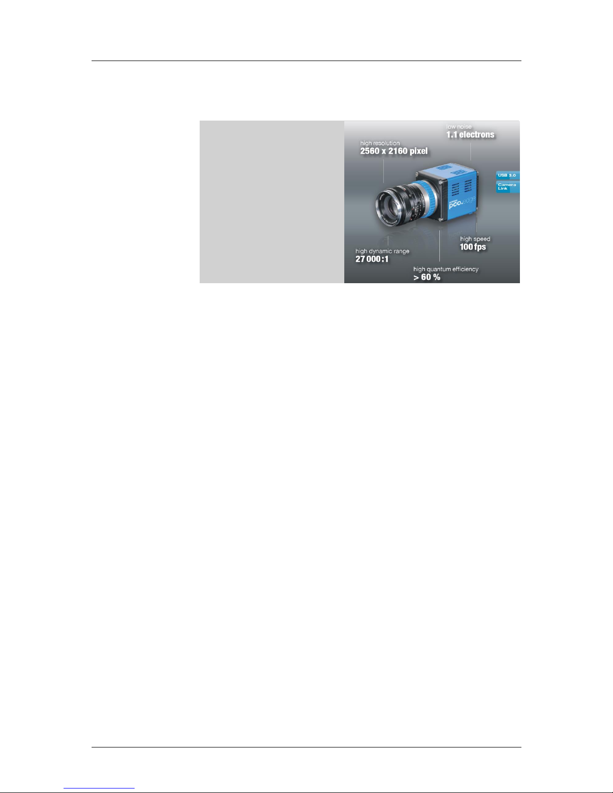
The pco.edge is a breakthrough in scientific imaging cameras, due to its
distinctive ability to simultaneously deliver extremely low noise, fast frame
rates, wide dynamic range, high quantum efficiency, high resolution and a
large field of view - all in one image.
The camera series’ main features are:
low noise: 0.9 electrons med (pco.edge 4.2, slow scan)
high resolution: 5.5 megapixel (pco.edge 5.5)
high dynamic range: 33000:1 (pco.edge 4.2, slow scan)
high speed: 100 fps @ full resolution (pco.edge 4.2 & 5.5, Camera Link)
deep cooling: - 30 °C (pco.edge GOLD, water cooling)
flexibility: user selectable choice of shutter mode
free of drift: stabilized Peltier cooling in order to avoid any drift
phenomena in image sequences
scientific CMOS

1 Introduction
6
pco.edge User Manual V1.03 © PCO AG, Germany
Overview – Available Camera Models
This table shows an overview over all available camera models.
Type
Interface
Shutter
Read Out Frequency
Sensor
pco.edge 4.2
USB 3.0
Rolling (RS)
110 MHz
mono
pco.edge 4.2
Camera Link
Rolling (RS)
95.3 MHz (slow scan)
mono
272.3 MHz (fast scan)
mono
pco.edge GOLD 4.2
USB 3.0
Rolling (RS)
110 MHz
mono
pco.edge 5.5
USB 3.0
Rolling (RS)
86 MHz
mono &
color
Global (GS)
(under development)
pco.edge 5.5
Camera Link
Rolling (RS)
95.3 MHz (slow scan)
mono &
color
286 MHz (fast scan)
Global (GS)
slow scan, not available*
286 MHz (fast scan)
Global Reset
(GR)
95.3 MHz (slow scan)
286 MHz (fast scan)
pco.edge GOLD 5.5
USB 3.0
Rolling (RS)
86 MHz
mono &
color
Global (GS)
(under development)
*since the image quality in Global Shutter Mode decreases with slower readout frequency, the slow scan mode is disabled.
Areas of Application
live cell microscopy
single molecule detection
localization microscopy
lightsheet microscopy
selective plane illumination microscopy
SPIM
structured illumination microscopy
SIM
TIRF microscopy / waveguides
spinning disk confocal microscopy
genome sequencing (2nd and 3rd gen)
FRET
FRAP
lucky astronomy / imaging
adaptive optics
solar astronomy
fluorescence spectroscopy
bio- & chemi-luminescence
high content screening
photovoltaic inspection
x-ray tomography
ophtalmology
flow cytometry
biochip reading
machine vision
TV / broadcasting
spectral (hyperspectral) imaging
laser induced breakdownspectroscopy (LIBS)
2 Safety Instructions
pco.edge User Manual V1.03 © PCO AG, Germany
7
2 Safety Instructions
Never operate the camera in humid or dusty environments or in places with
high amounts of X-ray radiation. Humidity, dust or X-rays could damage
the camera.
To avoid the risk of water condensation, protect the camera against
extreme changes of ambient temperature. If condensation enters the
camera, there is the risk of electric shock.
To prevent damage to the camera, the system must be kept stable and
protected against strong jolts or vibrations. The socket at the bottom of
the camera is to be used for mounting purposes only.
The slits in the camera case (side & back planes) are designed for heat
dissipation by the camera fan. To prevent overheating of the camera, do
not block these slits. Do not leave the camera system in direct sunlight to
avoid the risk of overheating.
Electric shock warning – Never slide any items through the slits into the
camera because of the risk of electric shock if the voltage parts inside are
touched.
Each time the camera is used, check the power cable for any damage.
Never position the cable in a way that it could become a tripping hazard.
Do not force the lens onto the camera. To protect the lens connector thread
from damage, use minimal force when attaching a lens to the camera.
If any of the following conditions apply, immediately switch off the camera,
separate it from the power line and contact our customer support:
If the power cable or the power plug seems to be worn or
damaged.
If liquids have penetrated the device.
If, after thoroughly reviewing the instruction manual, the device is
still not operating properly.
If the camera has been dropped or the casing is damaged.
3 System Components
8
pco.edge User Manual V1.03 © PCO AG, Germany
3 System Components
A camera system includes all parts which are necessary to install and run
your camera. If you purchased a water cooling system with your camera,
please see Appendix 7.
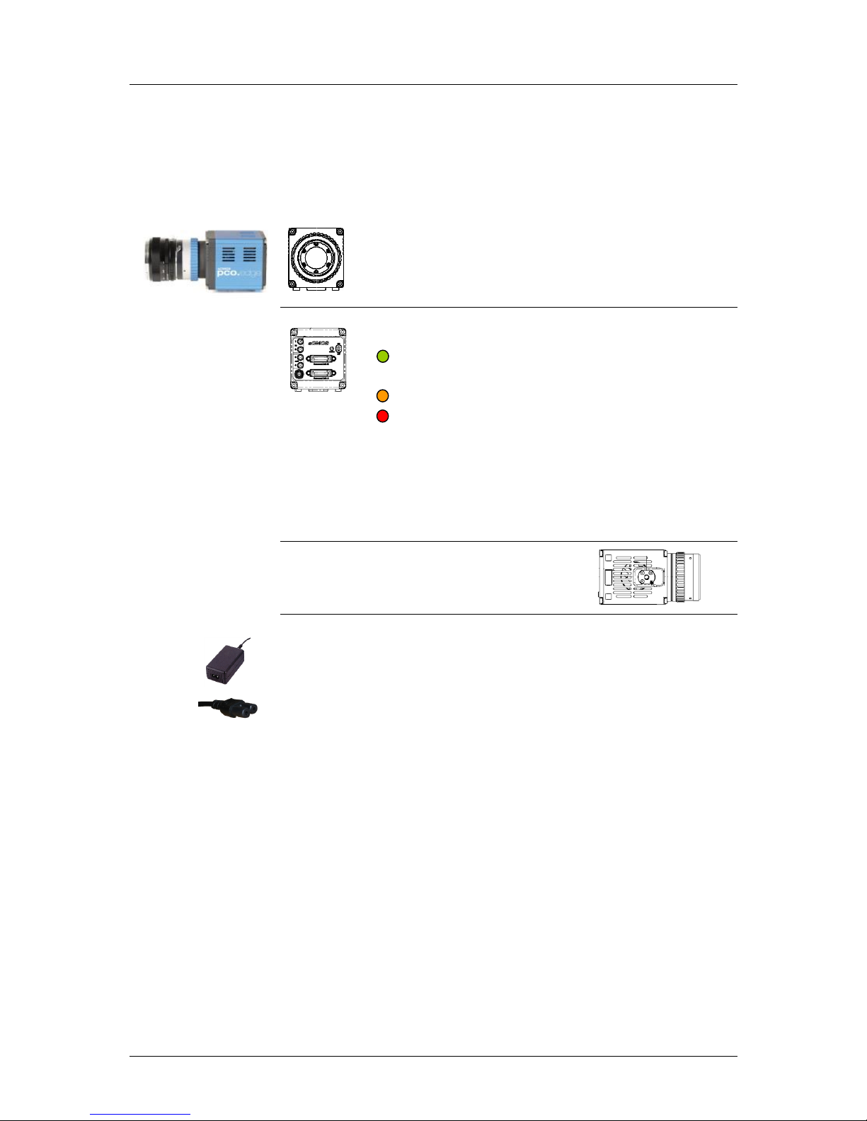
Camera Head
F-mount optical connection (standard)
For standard F-mount/SLR lenses and adapters.
C-mount ring provided (see appendix A3)
For standard C-mount and microscopy connectors.
LED indicates camera status
green continuos: camera is booting
green blinking: camera is ready for operation
yellow blinking: recording on
red blinking: error
Input/Output 4x SMA connectors
2x input - 2x output
Interface (user selectable)
Dual Camera Link 'full' or
USB 3.0
1/4-20 UNC mounting thread
Serial Number tag
Power Supply
Your system will be equipped with either a 24 V or a 12 V power supply,
depending on the model you selected. (connector: Lemo FGG.0B)
Power Cord (optional)
Standard IEC7 connector (please refer to your local dealer)
Camera Link Grabber Card / USB 3.0 PCI Interface Card
PCI Express x4 Card (Camera Link “full”) or
PCI Express x1 Card (2 x USB 3.0 connections)
Note: A PCI Card with 4 x USB 3.0 connections is also available, contact PCO for further details. A PCIe x4
slot is necessary for this card.
Cables
2x Camera Link cables (3m) or
1x USB 3.0 cable (3m)
Note: If a longer cable length is required, contact PCO for available solutions.
Digital Camera Tools (USB storage device)
The accompanying USB storage device contains:
• Camware: software for camera control & image acquisition
• camera & grabber board drivers
4 Installation
pco.edge User Manual V1.03 © PCO AG, Germany
9
4 Installation
You will find all necessary files on the accompanying USB storage device.
You may also download the newest versions of our software, camera
drivers and third party software drivers from our website (support section).
Minimum computer system requirements:
Clock speed: 2.4 GHz
DDR3-RAM 4GB (1066 MHz)
Windows 7 64-bit (for full performance, see appendix A8)
1280 x 1024 pixel resolution display
nVIDIA CUDA GPU
4.1 Frame Grabber (Camera Link) / PCI Board Installation (USB 3.0)
When operating the camera with Camera Link Interface: Please run the
appropriate grabber driver installation (provided with the accompanying
USB stick) with default settings.
After the installation, shut down the computer and install grabber card
hardware. For further information please see appendix A9 (ME4 Grabber
Instruction).
When USB 3.0 is used to interface the camera, it is recommended to use
the PCI Interface card which is provided by PCO. For an installation
instruction or further hardware recommendations, see appendix A10.
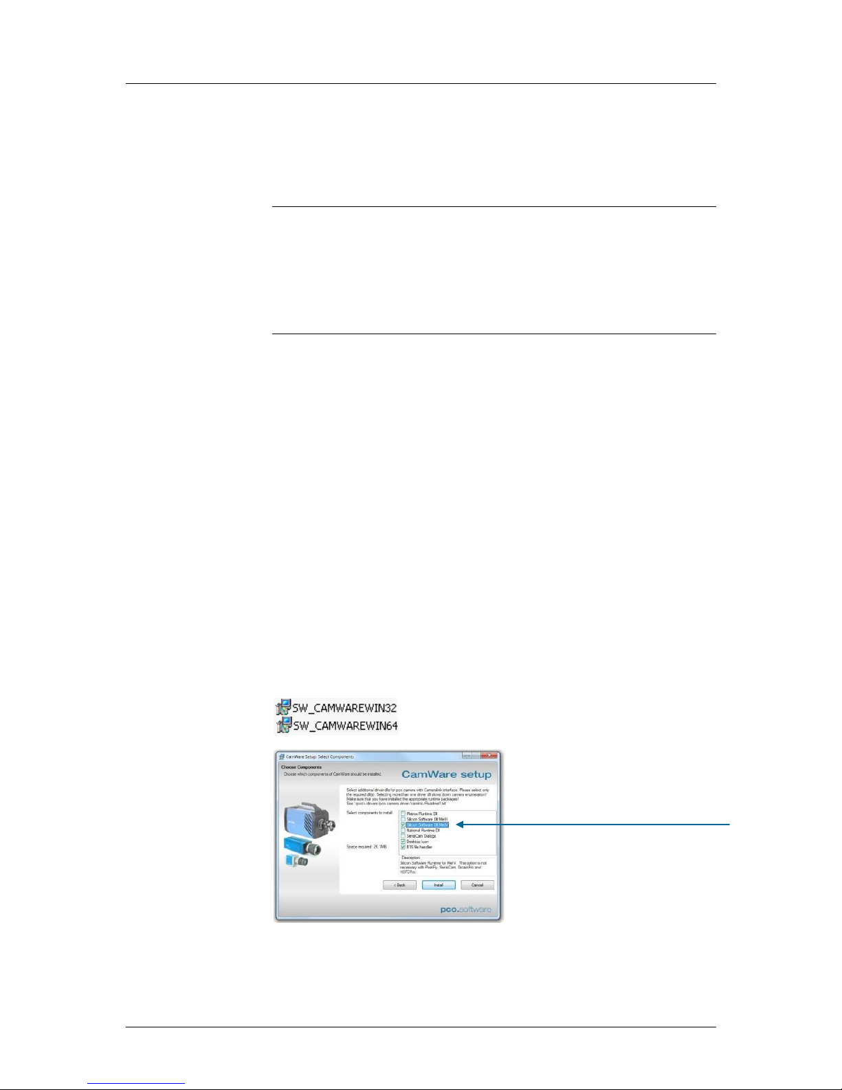
4.2 Camware
The pco.camware 32-bit/64-bit Windows application software enables you
to control every camera parameter or setting. Images can be displayed on a
monitor and may be downloaded and stored.
Please run the respective software installation provided on the USB storage
device:
After a successful installation, you will find the program folder ’Digital
Camera Toolbox’ in your program directory. (It may also appear in the
folder: User/AppData/Roaming)
Select the required runtime libraries!
“Dll MeIV” when you use Camera
Link Interface.
5 Quick Start
10
pco.edge User Manual V1.03 © PCO AG, Germany
5 Quick Start
Note: In order to get familiar with your new camera & software it might be
helpful, if you first aim at an object that is easy to focus and that can be
seen at standard light conditions.
5.1 Preparation
installation is finished (see chapter 4)
an appropriate lens is attached (remove cap!)
or the camera is attached properly to the microscope,
spectrograph or other scientific device
camera is connected to the power supply
camera is connected to the PC (connect cable “A” with
connectors “A” on PC and “A” on camera, cable “B” respectively)
computer is on
camera is on and ready (green blinking LED)
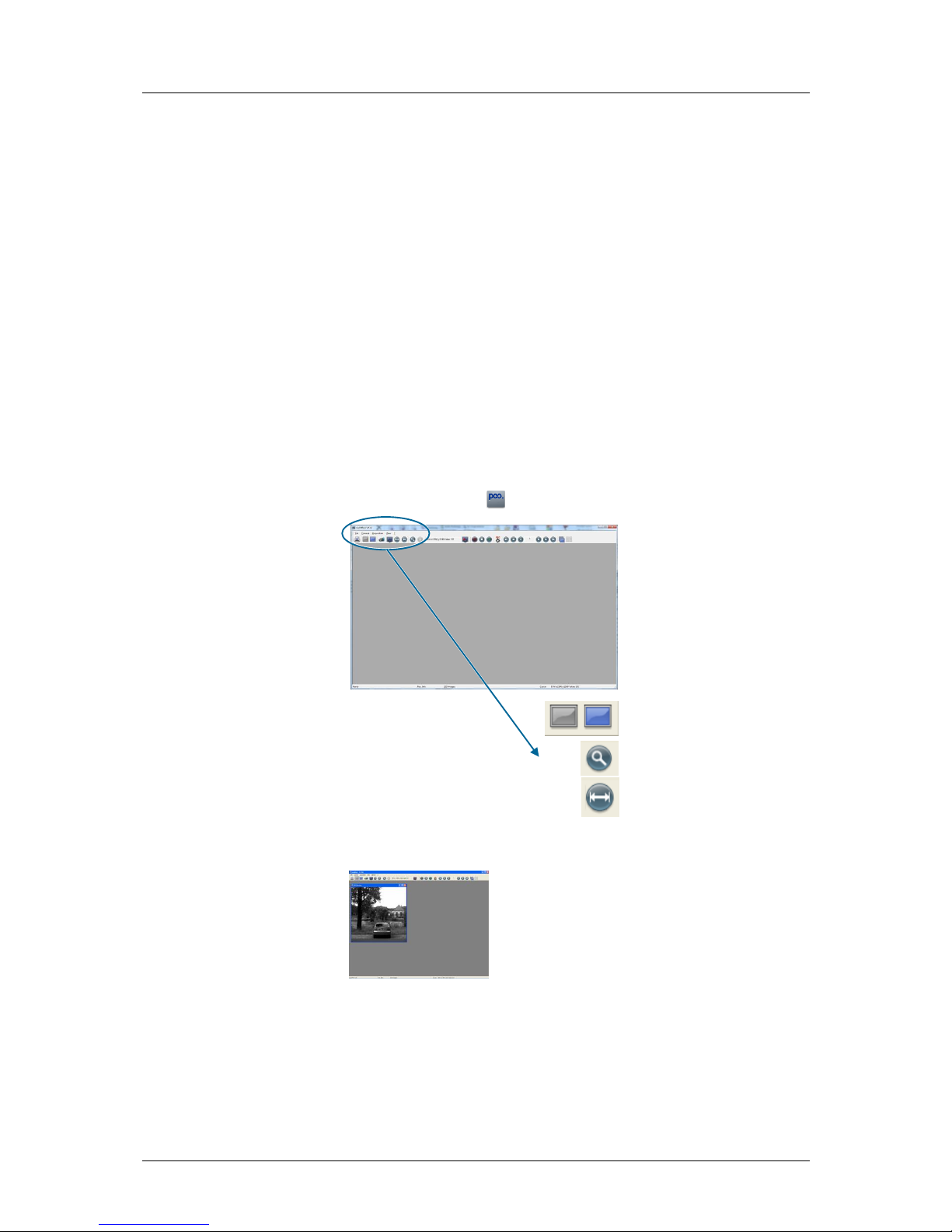
5.2 Start
start Camware
open view window
- if not already open -
start “live preview”
apply “auto range peak”
you may adjust aperture and focus
You should now clearly see the object in the
window.
If you need to change exposure time (e.g. the image is still either
too dark or too bright), please go to chapter 6!
If you want to record and save images, please see chapter 6 and
chapter 7 for detailed information!
6 Camera Control for the pco.edge
pco.edge User Manual V1.03 © PCO AG, Germany
11
6 Camera Control for the pco.edge
The 'Camera Control' window in Camware is the main interface for all
camera settings.
For further Camware features please see chapter 7!
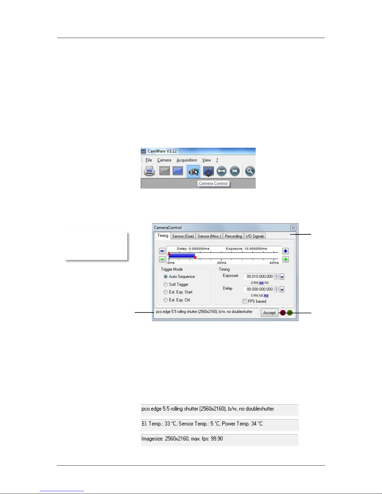
6.1 The “Camera Control” window
The camera control window can be opened by selecting the proper
command in the "Camera"-Menu or by the corresponding button in the
toolbar:
The camera control dialog always adapts to the camera type connected.
For the pco.edge the camera control settings are spread over five property
tabs , which will be explained below.
Changes to the camera control tabs must be completed by pressing the
“Accept” button .
If the "Accept" button is not pressed, these changes will be ignored and lost. The
camera control dialog automatically adjusts settings in case they are out of limits.
When the ‘Accept’ button is pressed the settings will be transferred to and validated by
the camera. If the camera accepts the settings the green LED will be highlighted.
The red LED will be highlighted in case a record is started.
In the information field you can view some information about the
camera. Click into the info field in order to scroll through the values.
Power Temp.: temperature hotspot close to FPGA
The camera control
dialog automatically
adjusts settings in case
they are out of limits.
6 Camera Control for the pco.edge
12
pco.edge User Manual V1.03 © PCO AG, Germany
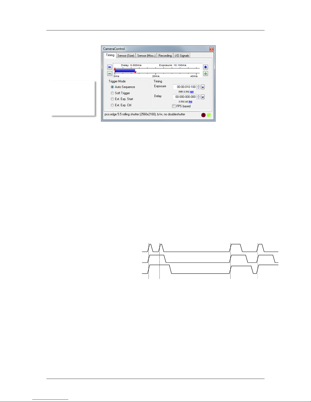
6.2 The “Timing” tab
Trigger Mode
[Auto Sequence] The camera will optimize the image recording depending
on the adjusted exposure time and the required readout time to achieve the
best possible frame rate (“free running”).
[Soft Trigger] Single images can be recorded with Camware control. A
single image can be acquired by pressing the "Single Trigger" button (7.2).
Other signals cannot influence this operating mode - for test purposes only.
[External Exp. Start] The image acquisition is triggered by an external
signal. It is also possible to force a software trigger for a test image with the
"Single Trigger" button.
In the [External Exp. Start] exposure control mode, single image
recording is started by the falling or rising edge of the voltage signal at
the BNC input #1 (6.6). The frame rate cannot be set, as the frame rate is
defined by the frequency of the external signal. However the predefined
exposure time and ROI settings affect the maximum possible frame rate.
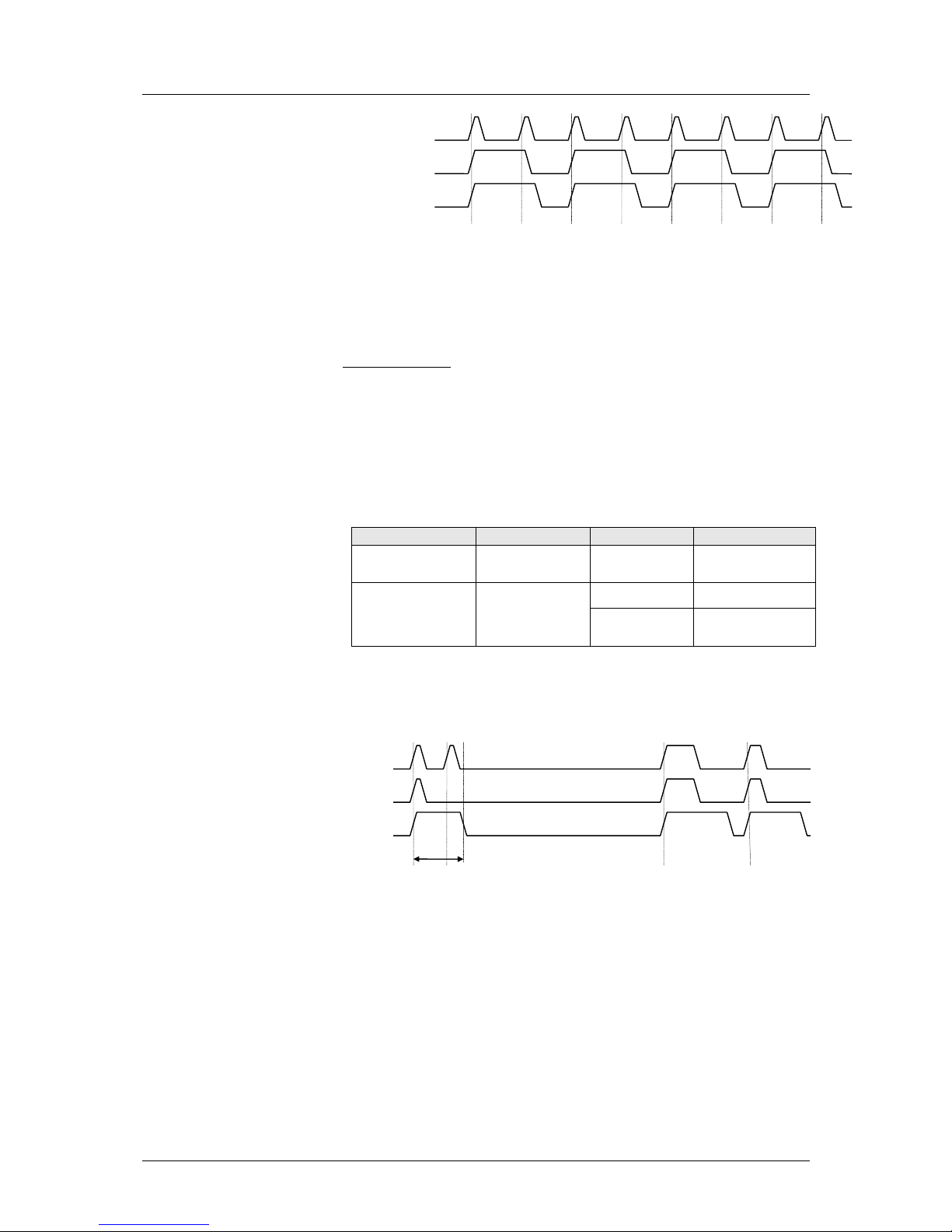
The Busy Status signal at BNC #3 (6.6) will indicate if a new trigger is
accepted.
The maximum achievable frame rate in external trigger mode is
negligibly less (about 0.1%) than operating the camera in [Auto
Sequence] mode.
Note: If the trigger rate of the external signal is quite near the maximum
possible frame rate (difference < 1/1000), then it will be random, whether
or not a trigger is accepted!
If the trigger rate of the external signal is higher than the maximum
possible frame rate, then every second trigger pulse is ignored.
Therefore the actual frame rate drops to ½ of the external trigger rate. If
the trigger rate is increased further, then only every 3rd, every 4th etc.
trigger edge will be accepted.
Busy Stat (out)
acc.
not acc.
accepted
accepted
exp trig (in)
Exp Stat (out)
In this context trigger
means exposure
trigger, i.e. the trigger
signal controls the
exposure of a single
image (light
integration time).
6 Camera Control for the pco.edge
pco.edge User Manual V1.03 © PCO AG, Germany
13
In order to avoid trade-offs at maximum frame rate use either the Busy
Status signal or make sure that the external trigger rate follows this
condition:
External Trigger Rate ≤ fmax / 1.001
[External Exp. Ctrl] An external signal applied at BNC #1 (6.6), controls the
start and the duration of the exposure.
A new exposure is started by the falling or rising edge of the voltage
signal at the BNC input. The exposure is finished when the opposite
edge is detected. Thus in this mode, the start as well as the length of the
exposure time can be controlled.
No further settings can be made, as the image timing is completely
controlled by the external trigger signal.
Be aware, that the externally controlled exposure time is limited. The
integration will be stopped automatically if the maximum exposure time
is achieved.
Camera
Interface
Shutter Mode
max. exposure time
pco.edge 4.2
pco.edge GOLD 4.2
Camera Link &
USB 3.0
Rolling Shutter
10s
pco.edge 5.5
pco.edge GOLD 5.5
Camera Link &
USB 3.0
Global Shutter
5s
Rolling Shutter
Global Reset
8s
The Busy Status signal at BNC #3 (6.6) indicates if a new trigger will be
accepted.
Busy Stat (out)
acc.
not acc.
exp trig (in)
Exp Stat (out)
acc.
not acc.
acc.
not acc.
acc.
not acc.
t
readout
Busy Stat (out)
acc.
not acc.
accepted
accepted
exp trig (in)
Exp Stat (out)

6 Camera Control for the pco.edge
14
pco.edge User Manual V1.03 © PCO AG, Germany
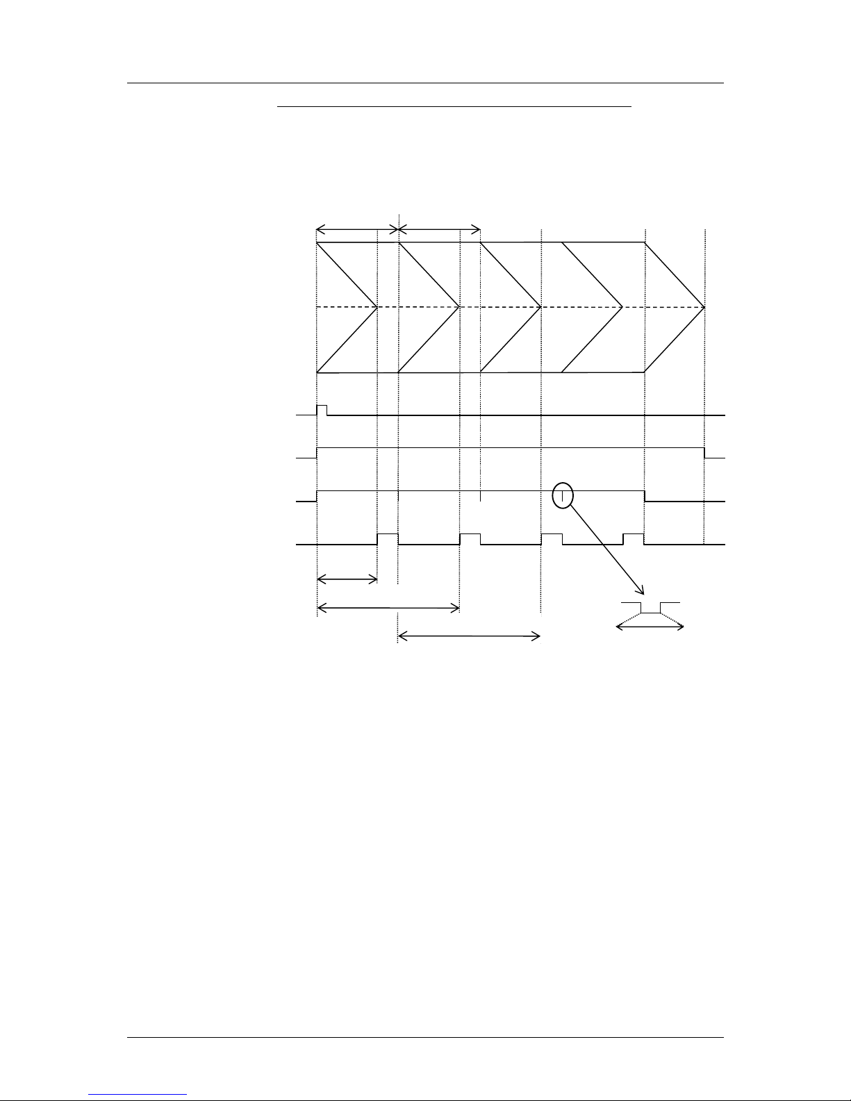
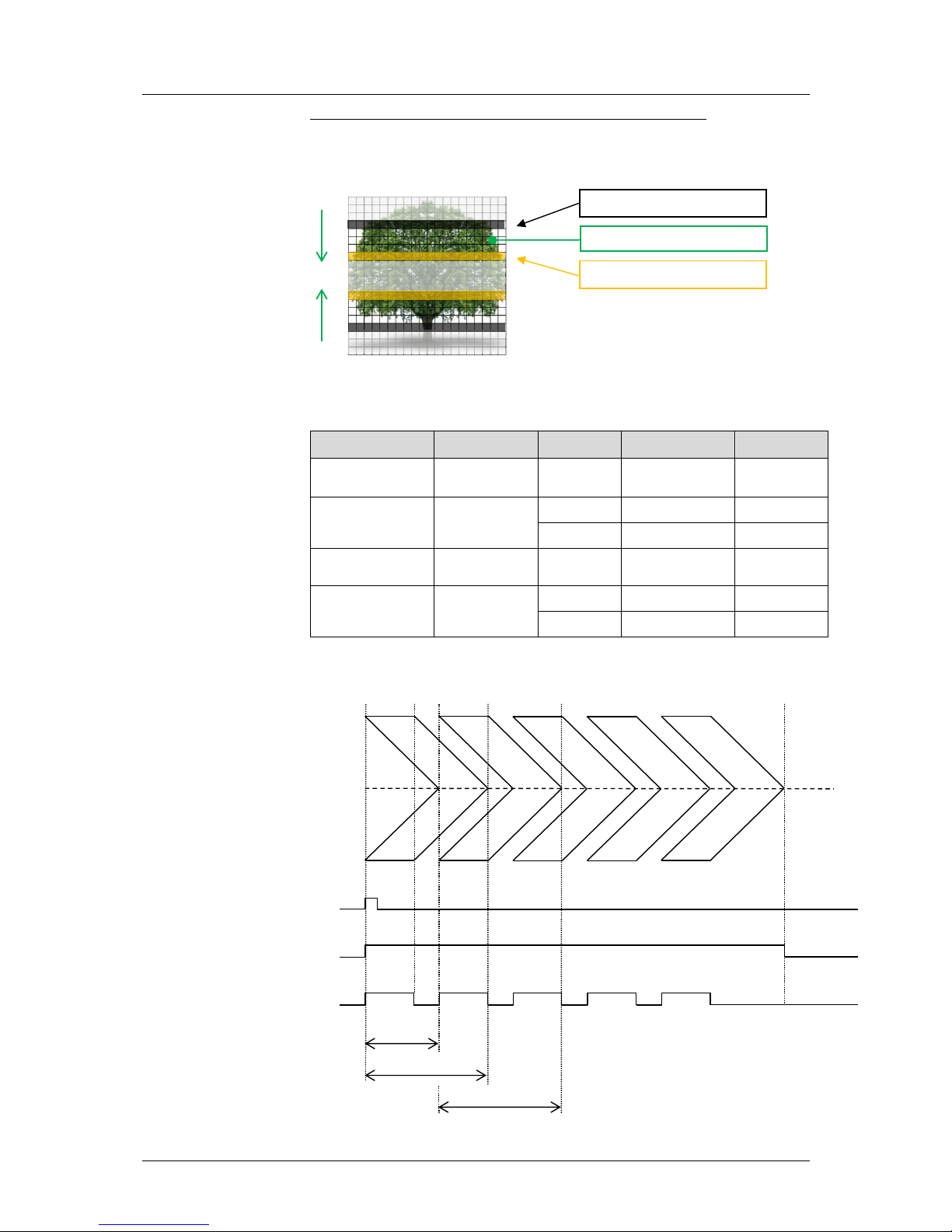
6.2.1 Rolling Shutter – Timing Details
In rolling shutter mode the pixel reset and exposure start is carried out row
by row. Each row has the same exposure time, but a different start of
exposure. The pco.edge image sensor consists of two discrete halves,
which are exposed and read out simultaneously, i.e. from the outside to the
center. Within one row, the exposure starts simultaneously for all pixels.
General Timing Diagram
Timing
The exposure and delay time can be adjusted in steps of 10µs.
Camera (RS only)
Interface
exposure time
delay time
pco.edge 4.2
Camera Link &
USB 3.0
500µs … 10s
0µs … 1s
pco.edge GOLD 4.2
USB 3.0
500µs ... 60s
0µs … 1s
pco.edge 5.5
Camera Link &
USB 3.0
500µs … 2s
0µs … 1s
pco.edge GOLD 5.5
USB 3.0
500µs ... 60s
0µs … 1s
reset
start
reset
end
readout
start
readout
end
t frame
t frame
t global
t exposure (first row)
t exposure (last row)
t all rows
The exposure time of each row
starts with the corresponding
reset of the row. Then after a
predefined time, exposure is
stopped. The light induced
accumulated charge carriers of
the pixels in a row are recorded
into memory in a low noise
fashion (readout). This results in
the total image appearing in
memory corresponding to the
row readout.
6 Camera Control for the pco.edge
pco.edge User Manual V1.03 © PCO AG, Germany
15
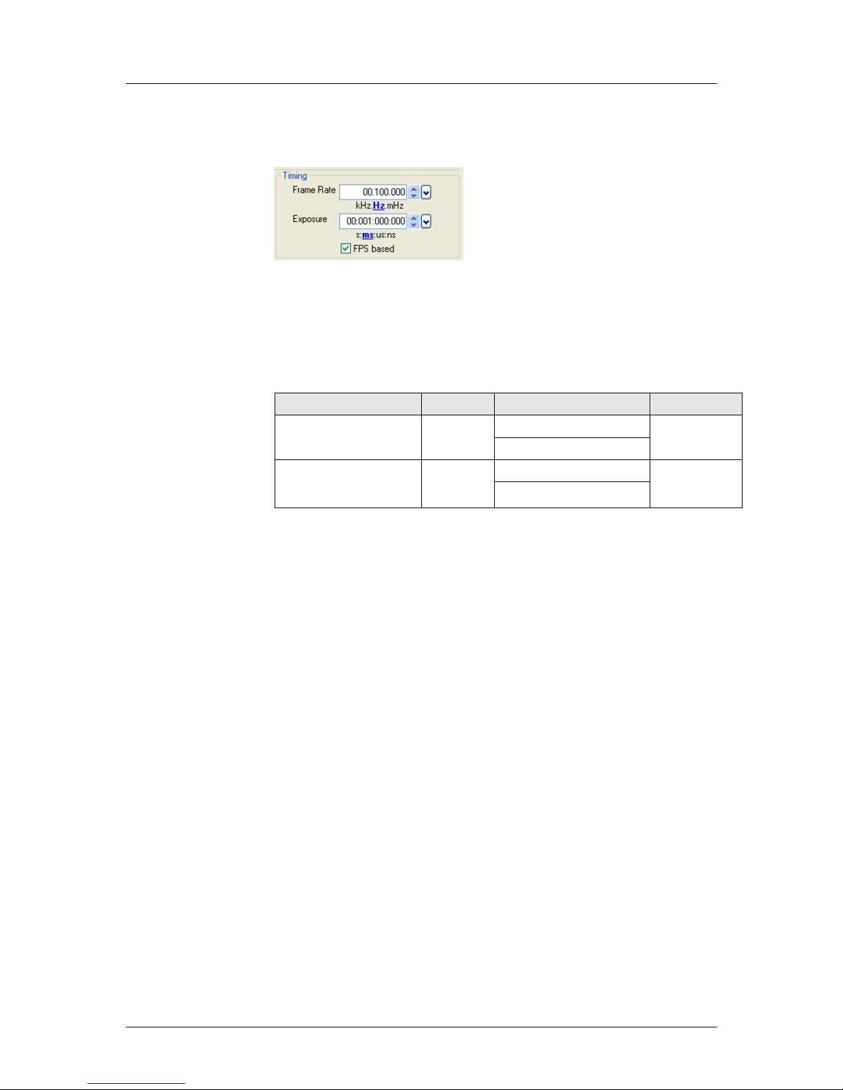
[FPS based] The camera will optimize the image recording to achieve the
selected frame rate with chosen exposure time as close as possible.
Note: • Only for [Auto Sequence] trigger mode
• “FPS based” mode only available with Camera Link Interface
First the frame rate is set. If the time required for readout of the image is
longer than 1 / frame rate, then the frame rate will be reduced to 1 / treadout.
The frame rate can be adjusted in steps of 100 mHz (rolling shutter).
If the selected exposure time would require a lower frame rate, the
exposure time is cut to the maximum possible time at that frame rate.
Camera (RS only)
Interface
Frame rate (FPS Based)
exposure time
pco.edge 4.2 (@ full resol.)
Camera Link
0.1 … 35 Hz @ 95.3 MHz
500µs … 10s
0.1 … 100 Hz @ 272.3 MHz
pco.edge 5.5 (@ full resol.)
Camera Link
0.5 … 33.3 Hz @ 95.3 MHz
500µs … 2s
0.5 … 100 Hz @ 286 MHz
6 Camera Control for the pco.edge
16
pco.edge User Manual V1.03 © PCO AG, Germany
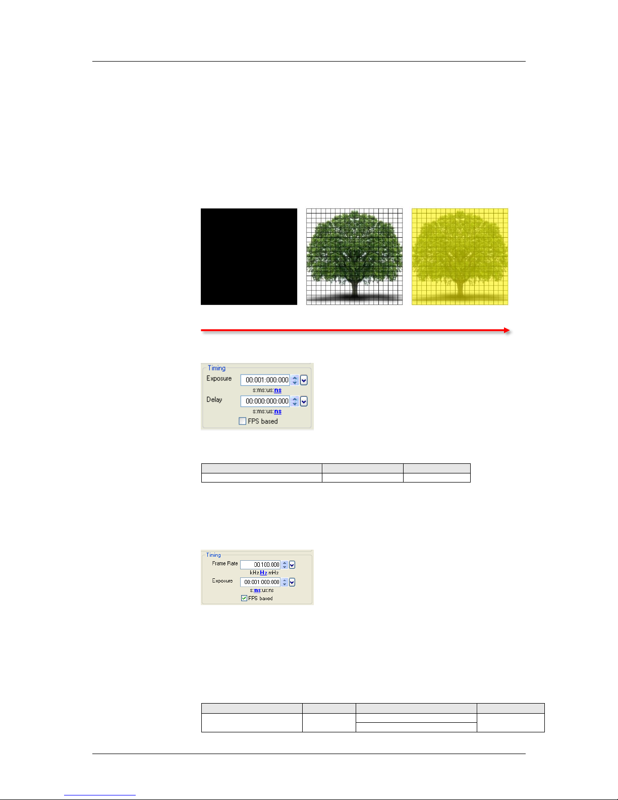
Exposure time > Sensor frame readout time (Auto Sequence)
In case the required exposure is longer than the frame readout time, the
image sensor is completely exposed to light for some time (tglobal). In case
of a triggered flash illumination, this would be the best moment to illuminate
the image sensor.
The hardware signal for the time tglobal is available on connector #4 (Global
OUT). Setting can be made through SDK (not available in Camware).
Obviously, if during exposure and readout, parts of the viewed image are
moving horizontally, this would result in image distortion. This is why the
global shutter mode may be a prerequisite for some applications.
However, most dynamic events can be captured in 1 ms, which is a
common integration time with SLR cameras set at 1/1000 exposure. The
time shift from one row to another is only about 10 µs (fast scan). The
resulting maximum readout time of 10 ms (@ full resolution) seems to be
sufficient for a broad spectrum of dynamic events.
The 10ms is also faster than the image shift process of most frame transfer
emCCD image sensors previously used for low light applications. If this
does not influence the image recording and processing, then rolling shutter
mode will not affect it either.
tframe
t all rows 2nd image
expos
global
trigger
busy (OUT)
t exposure
1st row, 1st image
t exposure
1st row, 2nd image
t all rows 1st image
Δt = t
6 Camera Control for the pco.edge
pco.edge User Manual V1.03 © PCO AG, Germany
17
exposure stop & readout
reset & exposure start
band of simultaneous exposure
Exposure time < Sensor frame readout time (Auto Sequence)
In case the required exposure is shorter than the frame readout time, the
image is composed of two exposure bands moving from the outside to the
center of the sensor.
For example, the shortest exposure time in RS is 500µs. The band of
simultaneous exposure is in this case (smallest possible height):
Camera (RS only)
Interface
MHz
time per row
min. number
of simult. rows
pco.edge 4.2
pco.edge GOLD 4.2
USB 3.0
110
24.10 µs
20
pco.edge 4.2
Camera Link
95.3
27.60 µs
18
272.3
9.65 µs
51
pco.edge 5.5
pco.edge GOLD 5.5
USB 3.0
86
30.50 µs
16
pco.edge 5.5
Camera Link
95.3
27.52 µs
18
286
9.17 µs
54
Previous comments on image distortion (also known as “Rolling Shutter
Effect”) apply here as well.
expos
trigger
busy (OUT)
tframe
t all rows 2nd image
t all rows 1st image

6 Camera Control for the pco.edge
18
pco.edge User Manual V1.03 © PCO AG, Germany
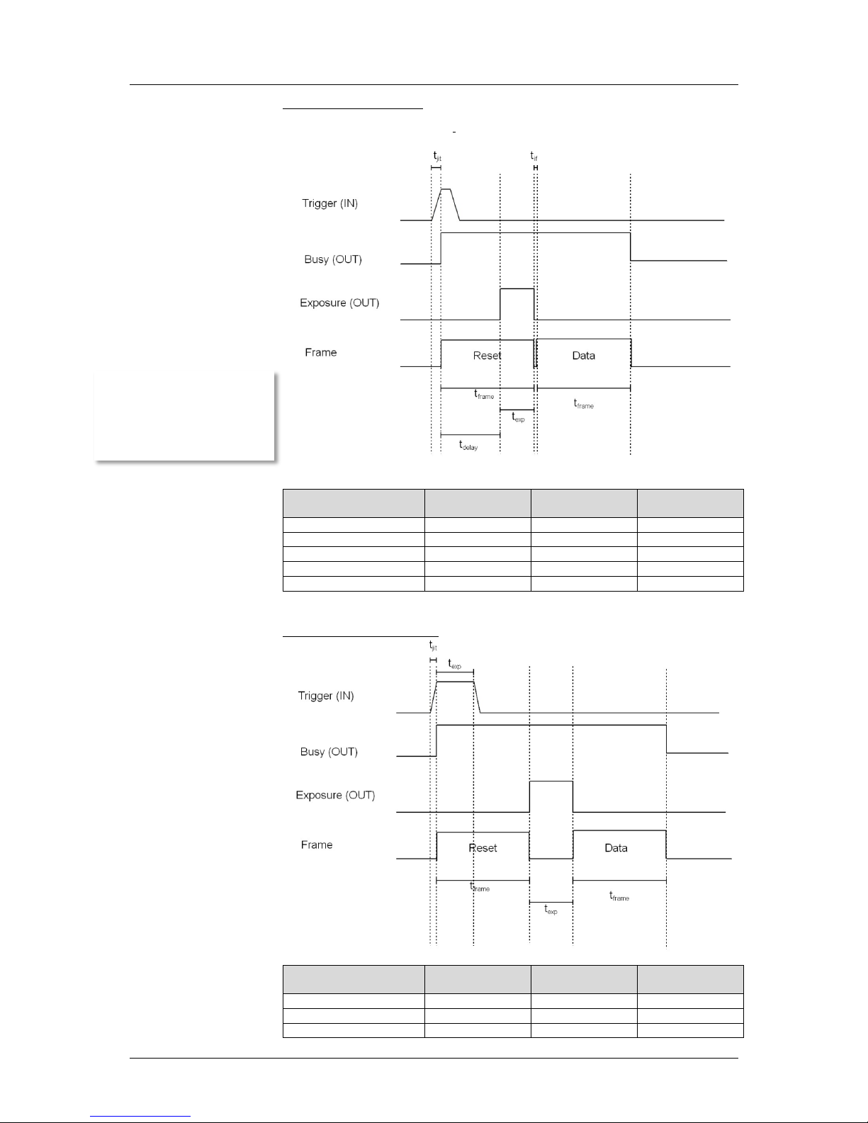
Details for [External Exp. Start] and [External Exp. Ctrl]
The detailed timing for external trigger includes system delay times, an
adjustable additional delay time, and the jitter.
Camera (RS only)
Interface
internal
system clock
tsys
tjit (jitter)
≙1 row time
tdelay
(delay)
pco.edge 4.2
pco.edge GOLD 4.2
USB 3.0
100 MHz
50 ns
0 ... 24.10 µs
0 … 1s
pco.edge 4.2
Camera Link
72 MHz
70 ns
0 ... 27.60 µs
(slow scan)
0 … 1s
0 … 9.65 µs
(fast scan)
0 … 1s
pco.edge 5.5
pco.edge GOLD 5.5
USB 3.0
100 MHz
50 ns
0 … 30.50 µs
0 … 1s
pco.edge 5.5
Camera Link
72 MHz
70 ns
0 ... 27.52 µs
(slow scan)
0 … 1s
0 … 9.17 µs
(fast scan)
0 … 1s
For optimized synchronization (minimized jitter time) use the falling edge of
the line signal at the status output (see SDK description).
t
fsys
exposure
exp trig (in)
t
rsys
t
jit
t
jit
t
delay
t
delay
6 Camera Control for the pco.edge
pco.edge User Manual V1.03 © PCO AG, Germany
19
6.2.2 Global Shutter – Timing Details
First, all pixels are globally reset and these reset values are shifted into socalled diffusion nodes. From there, they are non-destructively read out into
memory as reset dark images. The exposure starts after transfer of the reset
dark image to the diffusion nodes, where they are stored on the chip. The
exposure is stopped by global charge transfer to the diffusion nodes. Then,
the exposure image is read out to the memory, where the former reset dark
image is subtracted to perform an external correlated double sampling,
which reduces the noise. Since two images have to be read out to receive
one resulting image, the sCMOS image sensor’s global shutter mode has
only half of the frame rate of the rolling shutter mode.
Reset Exposure Readout
Timing
The exposure and delay time can be adjusted in steps of 10µs.
Camera (GS only)
exposure time
delay time
pco.edge 5.5
10 µs .. 100 ms
0 µs … 1s
[FPS based] The camera will optimize the image recording to achieve the
selected frame rate with chosen exposure time as close as possible.
Note: • Only for [Auto Sequence] trigger mode
• “FPS based” mode only available with Camera Link Interface
First the frame rate is set. If the time required for readout of the image is
longer than 1 / frame rate, then the frame rate will be reduced to 1 / treadout.
The frame rate can be adjusted in steps of 1 mHz (global shutter).
If the selected exposure time would require a lower frame rate, the
exposure time is cut to the maximum possible time at that frame rate.
Camera (GS only)
Interface
Frame rate (FPS Based)
exposure time
pco.edge 5.5
Camera Link
10 … 16.7 Hz @ 95.3 MHz
10µs … 100ms
10 … 50 Hz @ 286 MHz
6 Camera Control for the pco.edge
20
pco.edge User Manual V1.03 © PCO AG, Germany
External Exposure Start
(Auto Sequence respectively)
# of lines
95.3 MHz
(slow scan)
286 MHz
(fast scan)
tjit 1 0 … 27.52 µs
0 … 9.17 µs
tframe
ROI (y)
29.76 ms (max)
10.00 ms (max)
texp
programmable
10 µs … 100 ms
10 µs … 100 ms
tdelay (system)
(tframe – texp)
tif 1 27.52 µs
9.17 µs
External Exposure Control
# of lines
95.3 MHz
(slow scan)
286 MHz
(fast scan)
tjit 1 0 … 27.52 µs
0 … 9.17 µs
tframe
ROI (y)
29.76 ms (max)
10.00 ms (max)
texp
counted
if t
exp
< t
frame
system delay (t
delay
) is
added before exposure
starts

6 Camera Control for the pco.edge
pco.edge User Manual V1.03 © PCO AG, Germany
21
In [External Exposure Control] trigger mode the external signal controls start
of image acquisition and duration of the exposure. First, all pixels are
globally reset and these reset values are shifted into so-called diffusion
nodes. From there, they are non-destructively read out into memory as
reset dark images.
In this mode, the exposure starts always after the readout of the dark image
is completed. The length of the exposure has been detected by the sensor
from the trigger input. The exposure is stopped by global charge transfer to
the diffusion nodes after the respective time. Then, the exposure image is
read out to the memory, where the former reset dark image is subtracted to
perform an external correlated double sampling, which reduces the noise.
Since two images have to be read out to receive one resulting image and
the exposure cannot start during readout time of the dark image, this
specific global shutter mode provides less than half of the frame rate of the
rolling shutter mode.
6 Camera Control for the pco.edge
22
pco.edge User Manual V1.03 © PCO AG, Germany
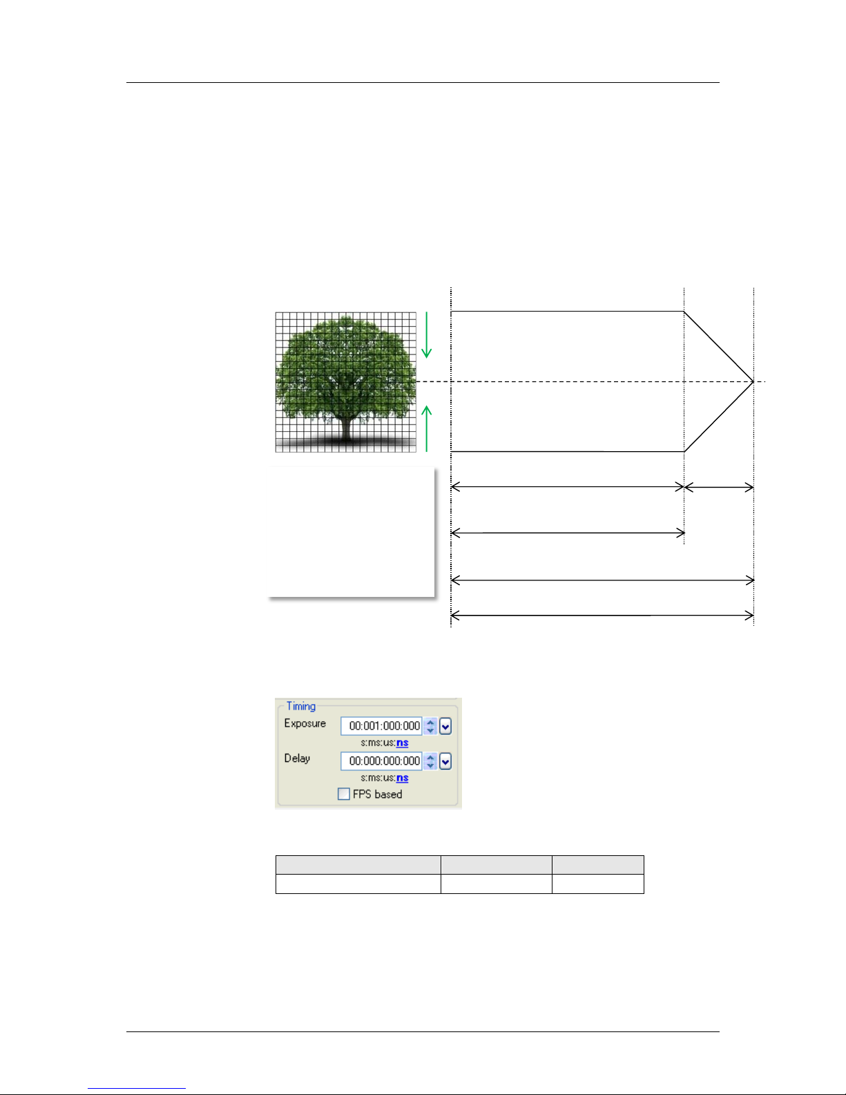
6.2.3 Global Reset – Timing Details
All pixels are globally reset, and the exposure starts for all rows at the same
time. The exposure stop is carried out row by row, therefore the duration of
the exposure is not the same for all pixels. The rolling readout improves the
image quality, but due to the difference in exposure time, a flash illumination
is recommended. The readout (exposure stop) is done from the outside to
the center.
General Timing Diagram
Timing
The exposure and delay time can be adjusted in steps of 10µs.
Camera (GR only)
exposure time
delay time
pco.edge 5.5 (global reset)
10 µs – 2 s
0 µs … 1s
reset /
exposure start
readout
start
readout
end
t frame
t global
t exposure (first row)
t exposure (last row)
t all rows
The exposure time of all rows
starts simultaneously. The
exposure time of the first row
stops after the predefined time,
the following rows are read out
from the outside to the center
row by row. Please note that
this leads to a different duration
of exposure time for all rows.
 Loading...