

Pco Dimax CS3, Dimax CS1, Dimax CS Series, Dimax CS4 User Manual
pco.
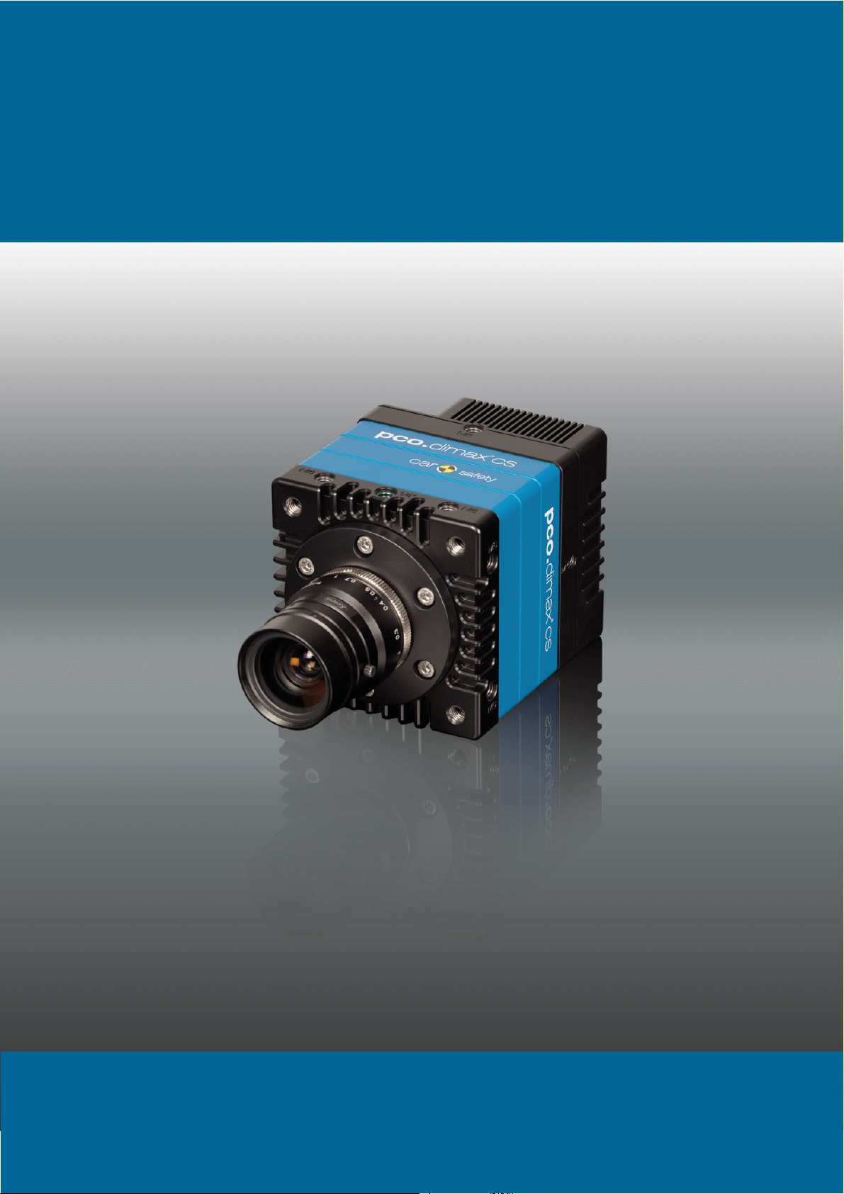
dimax cs
pco.
user manual

CO asks you to read this manual carefully before using the
P
pco.dimax cs camera system and follow the instructions.
Contact us for further questions or comments.
telephone +49 (0) 9441 2005 50
fax +49 (0) 9441 2005 20
email info@pco.de
postal address PCO AG
cover picture shows a typical PCO camera system.
The
Donaupark 11
93309 Kelheim, Germany
The lens is sold separately.
C
opyright © 2017 PCO AG (called PCO hereinafter), Kelheim, Germany. All
rights reserved. PCO assumes no responsibility for errors or omissions in
these materials. These materials are provided as is without warranty of any
kind, either expressed or implied, including but not limited to, the implied
warranties of merchantability, fitness for a particular purpose, or noninfringement. PCO further does not warrant the accuracy or completeness of
the information, text, graphics, links or other items contained within these
materials. PCO shall not be liable for any special, indirect, incidental, or
consequential damages, including without limitation, lost revenues or lost
profits, which may result from the use of these materials. The information is
subject to change without notice and does not represent a commitment on
the part of PCO in the future. PCO hereby authorizes you to copy documents
for non – commercial use within your organization only. In consideration of
this authorization, you agree that any copy of these documents, which you
make, shall retain all copyright and other proprietary notices contained
herein. Each individual document published by PCO may contain other
proprietary notices and copyright information relating to that individual
document. Nothing contained herein shall be construed as conferring by
implication or otherwise any license or right under any patent or trademark of
PCO or any third party. Except as expressly provided, above nothing
contained herein shall be construed as conferring any license or right under
any PCO copyright. Note that any product, process, or technology in this
document may be the subject of other intellectual property rights reserved by
PCO, and may not be licensed hereunder.
eleased September 2017 © PCO AG
R
pco.dimax cs user manual V1.04 © PCO AG, Germany

TABLE OF CONTENTS
1. INTRODUCTION 5
1.1 INTENDED USE 6
1.2 REASONABLE FORESEEABLE MISUSE 6
2. SAFETY INSTRUCTIONS 7
3. SYSTEM COMPONENTS 8
4. INSTALLATION 9
4.1 NVIDIA CUDA DRIVER 9
4.2 GIGE DRIVER 10
4.3 CAMWARE 11
5. QUICK START 12
5.1 PREPARATION 12
5.2 START 12
5.3 FIRST IMAGE 13
6. CAMWARE 4 SOFTWARE 14
6.1 INTRODUCTION 14
6.2 CAMERA OVERVIEW / LIST 15
6.3 CAMERA PROPERTIES 17
6.3.1 TIMING 18
6.3.2 IMAGE SIZE 22
6.3.3 SENSOR CONTROL 23
6.3.4 MEMORY 24
6.3.5 RECORDING CONTROL 24
6.3.6 STATUS 27
6.3.7 HARDWARE I/O CONTROL 28
6.3.8 CONVERT CONTROL 30
6.4 IMAGE OVERLAY 32
6.5 RECORDER TOOLS 33
6.6 VIEW WINDOW 35
6.7 RECORDER (IMAGES) 36
6.8 SETTINGS OVERVIEW 38
6.8.1 AUTO SAVE 39
6.9 CAMWARE FEATURES 41
6.9.1 DEMO MODE 41
6.9.2 FILE MENU 42
6.9.3 CAMERA MENU 44
6.9.4 ACQUISITION MENU 45
6.9.5 VIEW MENU 45
6.9.6 WINDOW MENU 47
6.9.7 HELP MENU 47
6.9.8 VIEW WINDOW MENU 48
6.9.9 ADDITIONAL FEATURES 50
PPENDIX 51
A
A1 TECHNICAL DATA 52
DATA SHEET 52 A1.1
REAR PANEL 53
DIMENSIONS 54
INPUT WINDOW FILTER 56
M
OUNTING 56 A1.5
3
A1.2
A1.3
A1.4

2 GIGABIT ETHERNET INTERFACE 57
A
QUICK INSTALLATION GUIDE 57 A2.1
NETWORK INTERFACE CARD 58
A2.2.1 IP ADDRESS CONFIGURATION 59
A2.2.2 JUMBO PACKETS / BUFFER SETTINGS 60
A2.2.3 RECOMMENDED HARDWARE 61
A2.2.4 NETWORK ENVIRONMENT/PATCH CABLE 61
A2.2.5 CABLE LENGTH 61
SINGLE/MULTIPLE CAMERA OPERATION 62 A2.3
A2.3.1 SINGLE CAMERA 62
A2.3.2 MULTIPLE CAMERAS 63
A2.3.2.1 SWITCH 63
A2.3.2.2 SEVERAL NICS 64
DRIVER INSTALLATION 65 A2.4
A2.4.1 UNINSTALL DRIVER 65
A2.4.2 DE/ACTIVATING FILTER DRIVER (WIN7/8) 65
CALIBRATION TOOL 66 A2.5
A2.5.1 FIRMWARE WARNING 67
A2.5.2 BLOCKED ACCESS 67
A2.5.3 NETWORK AND PACKET DELAY 68
A2.5.4 SET CAMERA IP ADDRESS & PACKET DELAY 69
A2.5.5 IMAGE DATA TRANSFER RATE 70
A2.5.6 CAMERA TEST 70
A2.5.7 RESET IP ADDRESS 71
A2.5.8 TOOL TIPS 72
HELP GUIDE 72 A2.6
PERFORMANCE 73
A3 ACCESSORIES 74
BREAKOUT CABLE 74 A3.1
EXTENSION BOX 74
LENS CAGE 76
A4 MOUNT ADAPTER 77
PCO F-MOUNT ADAPTER 77 A4.1
CHANGE F- TO C-MOUNT / FOCAL DISTANCE 78
A5 HD-SDI 79
A6 IMAGE FILE FORMATS 80
A7 CUSTOMER SERVICE 82
SERVICE 82 A7.1
MAINTENANCE 82
RECYCLING 82
LOGFILE / SUPPORT FILE 83
TROUBLE SHOOTING 84
A8 INDEX 85
ABOUT PCO 86
A2.2
A2.7
A3.2
A3.3
A4.2
A7.2
A7.3
A7.4
A7.5
4
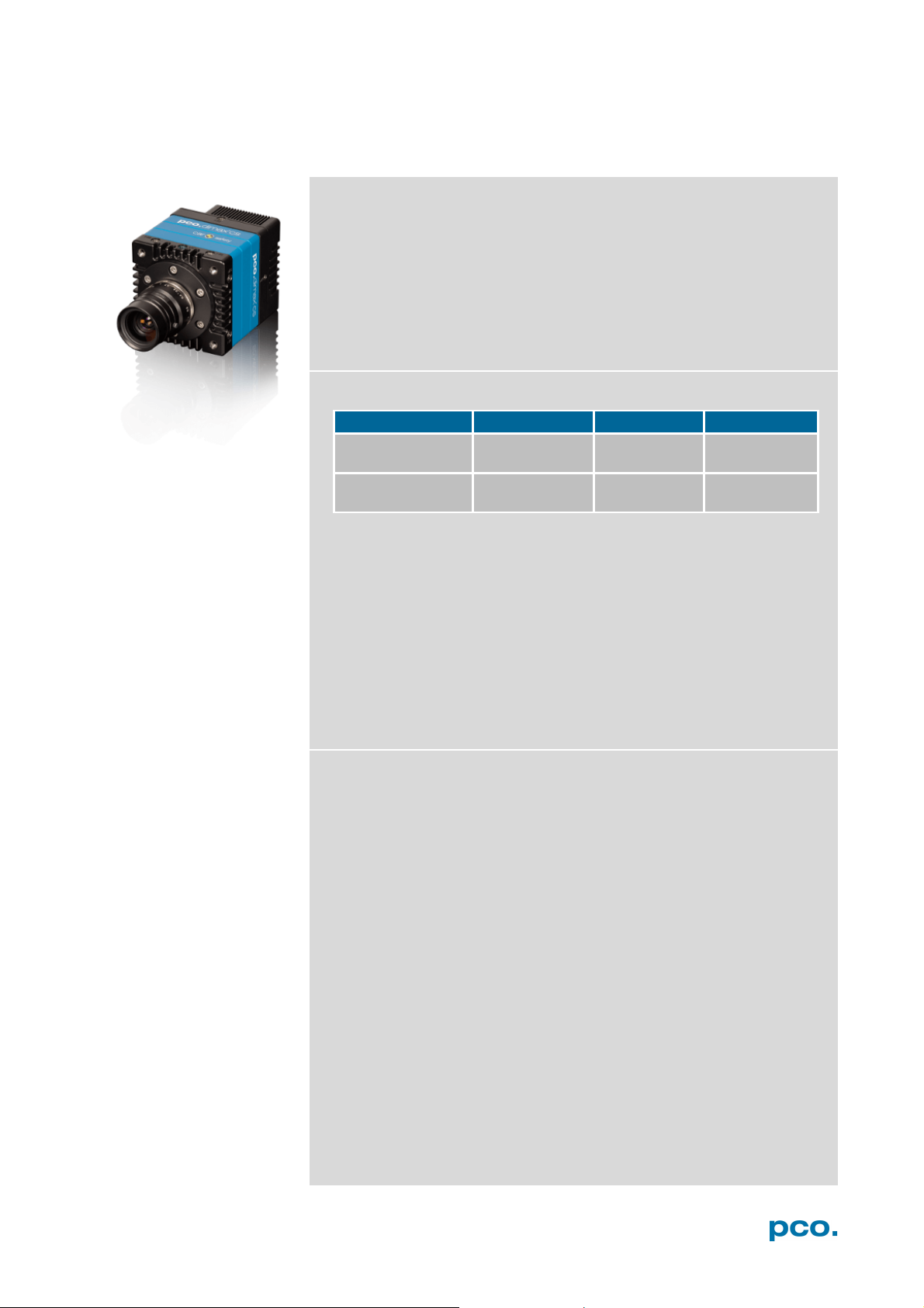
1 INTRODUCTION
pco.dimax cs1
pco.dimax cs3
pco.dimax cs4
Maximum resolution
(pixel)
Maximum speed
@full resolution (fps)
• automotive crash tests
• hydrodynamics
1. INTRODUCTION
High-speed meets high resolution.
This high-speed 12 bit CMOS camera series incorporates advanced
CMOS and electronics technology. It is perfectly suited for highspeed camera applications such as material testing, offboard crash
and sled or impact tests or super slow motion movie clips. The
camera systems feature also a variety of trigger options to cover all
off-board and on-board applications required by the automotive
industry.
The camera’s main features are:
• 12 bit dynamic range
• Color or monochrome image sensor versions available
• Correlated Double Imaging for superior image quality
• Exposure time range 1.5 μs - 40 ms
• Integrated image memory (RAM 9 GB)
• Double shutter operation (optional)
• Gigabit Ethernet (GigE) data interface
• HD-SDI video output
• Multiple trigger interface
• IRIG-B (unmodulated) from B000 to B007 and B120 to B127
Example areas of application
1296 x1024 1920 x 1440 2016 x 2016
3086 1603 1102
• high-speed particle image
• short time physics
• spray analysis
• material testing
• tensile tests
• airbag inflation
• fast flow visualization
velocimetry (PIV)
5
• fuel injection
• combustion imaging
• semiconductor quality
control
• fast events in nature and
industry
• super slow motion movie
clips
• ballistics

1.1 INTENDED USE
This camera system is designed for use by technicians, engineers
and scientists. It is a scientific measuring instrument, which provides
images. It is suited for applications with acceleration forces of up to
150G. The camera may only be used according to the instructions of
this manual. Provisions, limitations and operating conditions stated in
this manual must be respected. Unauthorized modifications or
alterations of the device are forbidden for safety reasons.
1.2 REASONABLE FORESEEABLE MISUSE
Overstress: It is not allowed to use the camera for applications with
acceleration forces higher than 150G.
Temperature: It is not allowed to use the camera beyond the
specified temperature range.
Use of lenses during onboard tests: only special C-mount lenses
(for high-G applications) are permitted. F-mount lenses must not be
used.
Accessories: It is not allowed to use the PCO Accessories for HighG
applications. The Extension box and the breakout cable must not
be used for high-G applications.
Open: opening the camera voids warranty.
6
2 SAFETY INSTRUCTIONS
NOTICE
NOTICE
NOTICE
NOTICE
NOTICE
NOTICE
DANGER
WARNING
CAUTION
CAUTION
2. SAFETY INSTRUCTIONS
Read the safety instructions completely.
DAMAGED POWER CABLE OR POWER PLUG
Danger to life due to electrical shock!
Each time the camera is used, check the power cable for
damage.
ELECTRIC SHOCK WARNING DUE TO VOLTAGE PARTS INSIDE
Risk of injury due to electrical shock!
Never slide any items through slits or holes into the camera.
MOISTURE
Risk of injury due to electric shock if moisture enters the camera.
To avoid the risk of water condensation, protect the camera
against extreme changes of ambient temperature.
TRIPPING HAZARD
Risk of injury from tripping over loose cables.
Never position the cable in a way that it could become a
tripping hazard.
HUMIDITY, DUST OR RADIATION
Humidity, dust or x-rays could damage the camera.
Never operate the camera in humid or dusty environments
or in places with high level of x-ray radiation.
SHOCK & VIBRATION
To avoid damaging the camera it must be firmly mounted and
protected against strong shocks or vibrations.
Use the camera's mounting threads to secure it.
LENS MOUNTING
Do not force the lens onto the camera.
To protect the lens connector thread from damage, screw
in the lens gently to avoid thread damage.
LIQUIDS DAMAGE CAMERA
If liquids have penetrated the device.
Switch the camera off immediately, detach it from power and
contact PCO's customer support.
DAMAGED CAMERA HOUSING
If the camera has been dropped or the body is damaged.
Switch the camera off immediately, detach it from power and
contact PCO's customer support.
IF CAMERA IS NOT WORKING PROPERLY
In case all actions following this manual to get the camera working
properly were unsuccessful.
Switch the camera off immediately, detach it from power and
contact PCO's customer support.
7
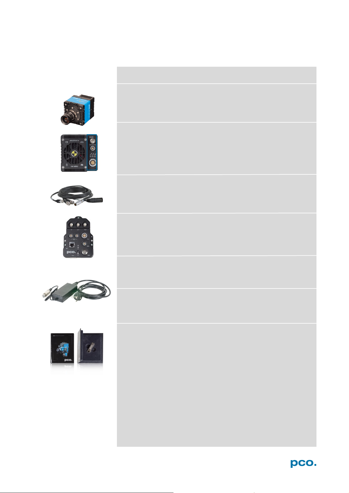
Rear Panel Connections (see A1.2)
Power Supply
Power Cord
3. SYSTEM COMPONENTS
The camera system includes the following parts.
Camera
F-mount + C-mount (exchangeable) optical connection
• Battery / Lens Controller
• LEDs indicate camera status
• Lemo Connector (Power - GigE - Trigger – Sync In/out – Stat out)
Breakout cable
RJ45 Cat6, BNC Sync In, BNC Trig In, XLR power
see chapter A3.1
Extension Box (optional)
see chapter A3.2
In: 100-240V AC 50-60Hz, 1.4A max. Out: 24V DC 2.71A
Standard IEC13 connector
Digital Camera Tools (USB flash drive content)
• Camware: software for camera control & image acquisition
• Manuals
• Driver & tools
• Software development kit (SDK) & demo programs in C and C++
8
4 INSTALLATION
1
2
1
2
4. INSTALLATION
You will find all necessary files on the accompanying USB flash drive.
You may also download the latest versions of our software, camera
driver and third party software drivers from our website.
Minimum system requirements:
• Clock speed > 2.4 GHz (Intel Core i7)
• RAM 4 GB
• Windows 7 or higher (no server version)
• Full-HD display
• Gigabit Ethernet GigE (1000 Mbps network interface card)
4.1 NVIDIA CUDA DRIVER
Update your NVIDIA driver for Camware 4. In case of an old driver
version GPU Processing will not work and therefore slow image
processing.
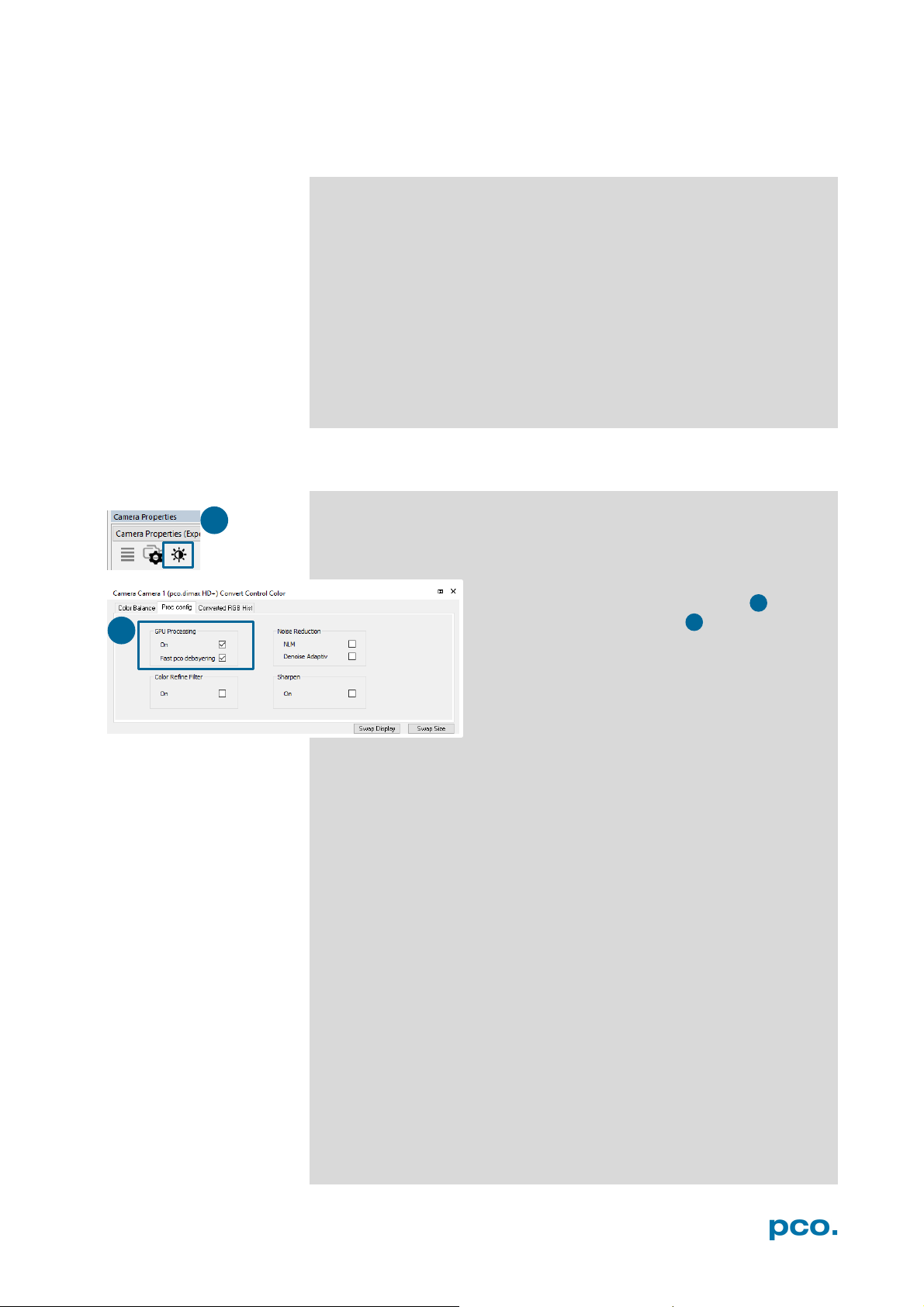
If GPU Processing is disabled and shown grayed, update your
NVIDIA driver or check the website of the computer manufacturer for
graphic card driver updates. Your NVIDIA driver version must be at
least 333.11 or higher.
Check if GPU Processing is activated by having
a look into the Proc config settings in the
Convert Control window (see Convert
Control chapter 6.3.8).
9

1
4 2 3
1 2 3
4
NOTE
installs both
allowing former GigE cameras to run
If installer fails, use
5
5
4.2 GIGE DRIVER
NOTE
uninstaller, remove all
old files and then try
again.
First install the PCO GigE driver to your computer, from the attached
usb flash drive or from the PCO website www.pco.de
Before installing, you have to remove previously installed GigE
driver. The installer will do this for you. Or open control panel →
programs and functions → and uninstall PCO GigE driver.
• Start the GigE driver setup and follow the instructions.
• Choose installation directory.
• GigE driver installation is completed.
• Reboot your computer to complete the installation.
• Start Calib Tool see A2
This installation process
drivers: Gen2 and the former Gen1 V3.1
properly.
.
10
4 INSTALLATION
1
2
3
4
1
1
2
3
4
4.3 CAMWARE
The Camware Windows application software enables to control every
camera parameter or setting. Images can be displayed on a monitor
and may be downloaded and stored. The enclosed USB flash drive
contains installation files for the software for latest Windows
operating systems in 32 / 64 bit.
After a successful installation, you will find the program file Digital
Camera Toolbox in your program directory and a Camware 32 / 64
button on your desktop. Other helpful tools are also installed in the
same directory.
To uninstall the Camware program, use the Software feature under
Windows’ System Control.
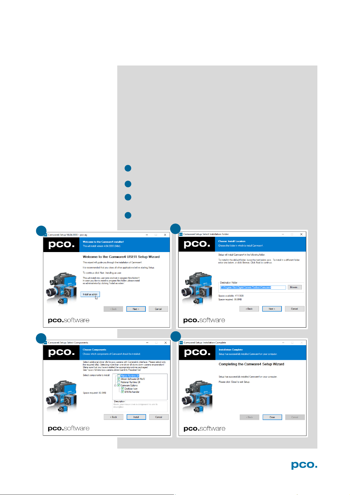
Follow the installation wizard
• Install Camware as Admin to install to program folder, instead it
will be installed only to user folder
• Choose install directory
Choose components: Select additional drivers for Camera Link
•
interface (not recommended for pco.dimax cs)
• After the next two screens installation is complete
11
NOTE
5. QUICK START
5.1 PREPARATION
In order to get familiar with your new camera and software it might be
helpful, first to aim the camera at an object easy to focus and visible
at normal light conditions.
• Computer is turned on
• Installation is finished (see chapter 4)
• An appropriate lens is attached (remove cap) or the camera is
attached properly to the microscope, spectrograph or other
scientific device
• Camera is connected to the power supply
• Camera is connected to the computer and switched on
• Camera is booted and ready after 5 to 20 s when a beep sounds
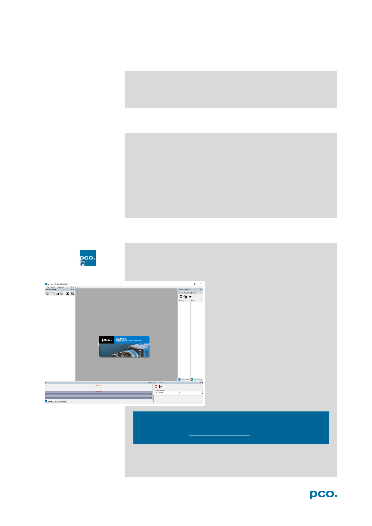
5.2 START
Start Camware and the graphical user interface will start up:
Always install latest Camware version to get the full functionality of
your pco camera (www.pco.de/support)
.
12
5 QUICK START
NOTE
2
3 4 5
6
2 3 6 4 5
1
1
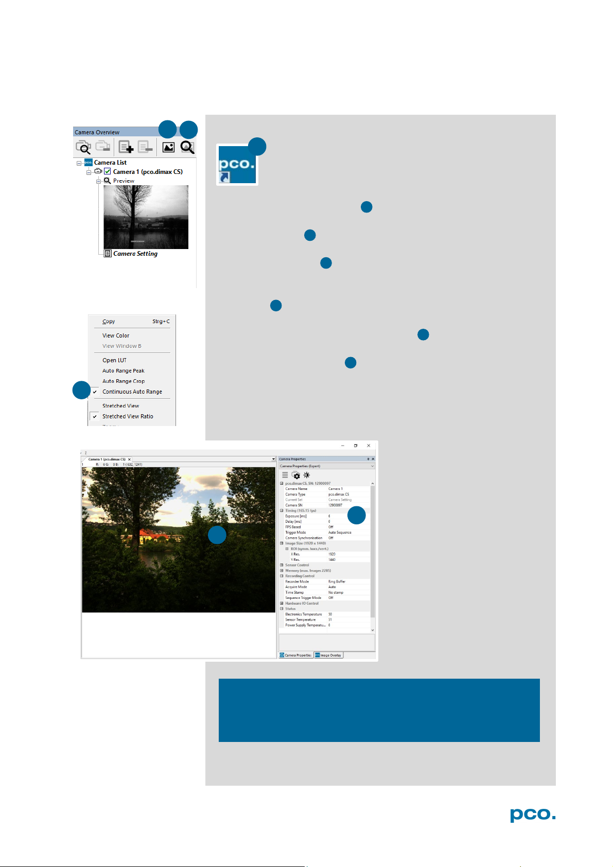
5.3 FIRST IMAGE
Follow the instructions:
• Camware must be started
• A view window is shown automatically, if not open a new one
• Start live preview
• Right-click into the view window and apply Continuous Auto
Range
• You may have to adjust exposure time , aperture and focus
• Now you should clearly see the object in the window
If you need to change exposure
time (e.g. the image is still either
too dark or too bright), go to
chapter 6.3.2.
For recording and saving
images, see chapter 6.3.8 and
chapter 6.6 for detailed
information.
Live preview: Useful for fast and easy camera adjustment and
focusing. Does not record and store images.
13

6.3.1 TIMING
Timing /Trigger modes/
6.3.2 IMAGE SIZE
ROI / Sensor format / Binning
6.3 .3 SENSOR CONTROL
CDI / Double shutter / Temperature
6.3.4 MEMORY
Camera Internal memory (RAM)
6.3.5 RECORDING CONTROL
Recorder Acquire Mode /
Timestamp / Sequence trigger
6.3.6 STATUS
Temperature
6.3.7 HARDWARE I/O CONTROL
Input and Output Options
6.3.8 CONVERT CONTROL
Contrast, Saturation, Gamma…
6.4 IMAGE OVERL AY
Overlay for recorded images
6.5 RECORDER TOOLS
Record / Play and Settings
6.6 VIEW WINDOW
View window functions
6.7 RECORDER (I MAGES)
Preview of recorded images
6.8 SETTINGS OVERVIEW
Overview of all parameter settings
6.9.1 DEMO MODE
If no camera is connected
6.9.2 FILE ME NU
Open / Save / Print files / Direct
Dialog / Lookup table
6.9.3 CAMERA MENU
Camera control / Close / Rescan
6.9.4 ACQUISITION MENU
Live preview / Acquire sequence /
switching
6.9.5 VI EW MENU
B/W or Color window / Convert
6.9.6 WINDOW MENU
New / Close / Split window
6.9.8 HELP MENU
Create Support file/ Logging /
6.9.8 VIEW WINDOW MENU
Right-click menu: Zoom; Flip;
6.9.9 ADDITIONAL FEATURES
White Balance, Contrast, ROI by
6. CAMWARE 4 SOFTWARE
PCO’s Camware is an outperforming software for camera
control, image acquisition and archiving of images in
various file formats. This chapter provides a detailed
description of all Camware functions.
Camware works with any kind of PCO camera. Visit
www.pco.de
6.1 INTRODUCTION
Chapter 6.2 Camera Overview / List: shows all connected cameras
and all set recording profiles
Chapter 6.3 describes the Camera Properties window. This is the
main interface for all camera settings.
the latest version of this software.
synchronization
Chapter 6.5 / 6.6 / 6.7 / 6.8 describe the recording functions
Chapter 6.9 introduces to further Camware features
record to file / Options / AVI Codec
Auto camera RAM segment
Control / Toolbars / Application
Look / Reset layout to default
Support mail / About Camware
Mirror; Rotate…
Mouse, Short-cut list
14
6 CAMWARE 4 SOFTWARE
1
1 2 3
4
2 3 4
5
6
5 6 5
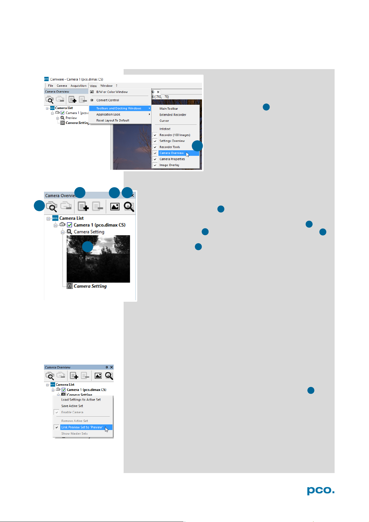
6.2 CAMERA OVERVIEW / LIST
The Camera Overview window supports management of more
than one PCO cameras and displays a list of the connected ones.
Camware is able to scan 2 for connected cameras or close a
connected camera. It allows to define several different Settings
for each camera (max. 30 sets per camera → add new set 3 ).
New view windows 4 can be opened and the Live Preview 5
function started. When opened up, the Preview shows a small
preview window 6 (always monochrome) integrated in the
camera list.
Live preview facilitates the aperture and focus adjustment,
allowing a first look at your object.
If closed, open the Camera Overview
window by selecting the View tab and
Toolbars and Docking Windows →
Camera Overview.
During Live preview Trigger and Acquire mode are set to Auto.
Camera Setting: all presettings, such as resolution and frame rate in
the Camera Properties (see 6.3) are saved to Camera Settings.
Define different Settings with different Preferences in Camera
Properties for each of your experiments. Settings can be switched
easily at any time (not during record) and copied to other cameras.
Link Preview Set to ‘Preview’
When Link Preview Set to Preview is ticked the Preview will always
be active with the set parameters when starting a Live Preview 5 .
In case this function is deactivated, the Live Preview will always
show live images with the parameters of your active setting.
Setting a higher exposure time for Preview set and linking it to the
preview function is beneficial if preview light conditions are different
from those in recording situations.
15
1
2
3
1 2 3
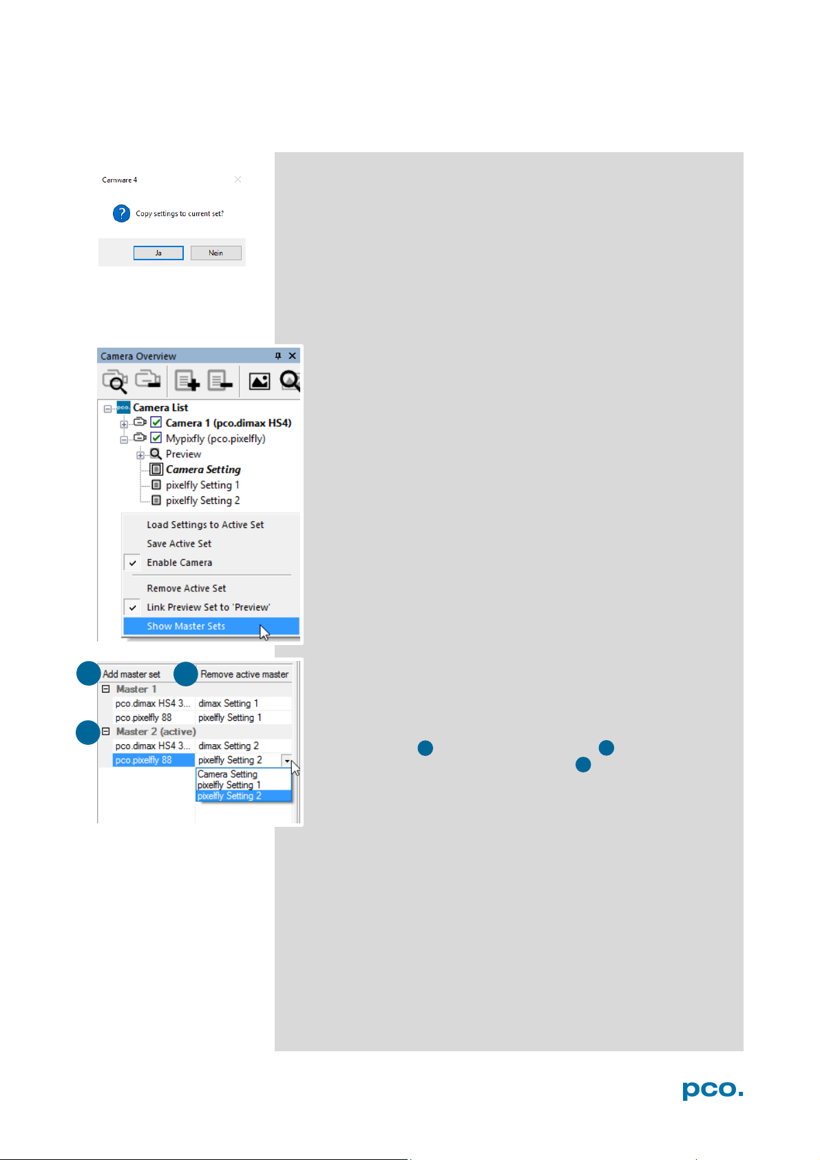
Click and drag camera setting: to copy e.g. Camera Setting 1 to
Camera Setting 4, just drag & drop Setting 1 to Setting 4 and
Camware will ask to confirm it. It is possible to copy each setting to
every camera.
Master Sets
This function facilitates image acqusition with multiple cameras.
Defining two or more Master Sets allows easy switching between
different predefined settings for each camera during an
experiment. Each image acquisition or experiment can be
recorded with its own Master Set.
To display Master Sets, right-click in the Camera Overview
window and click Show Master Sets.
Master Set window
Define different Master Sets. Select individual Camera Settings
within each Master Set.
Functions:
Add Master Set or Remove active master .
Activate it by clicking on one of your sets .
16
6 CAMWARE 4 SOFTWARE
1
2
3
1
2
3
4
4
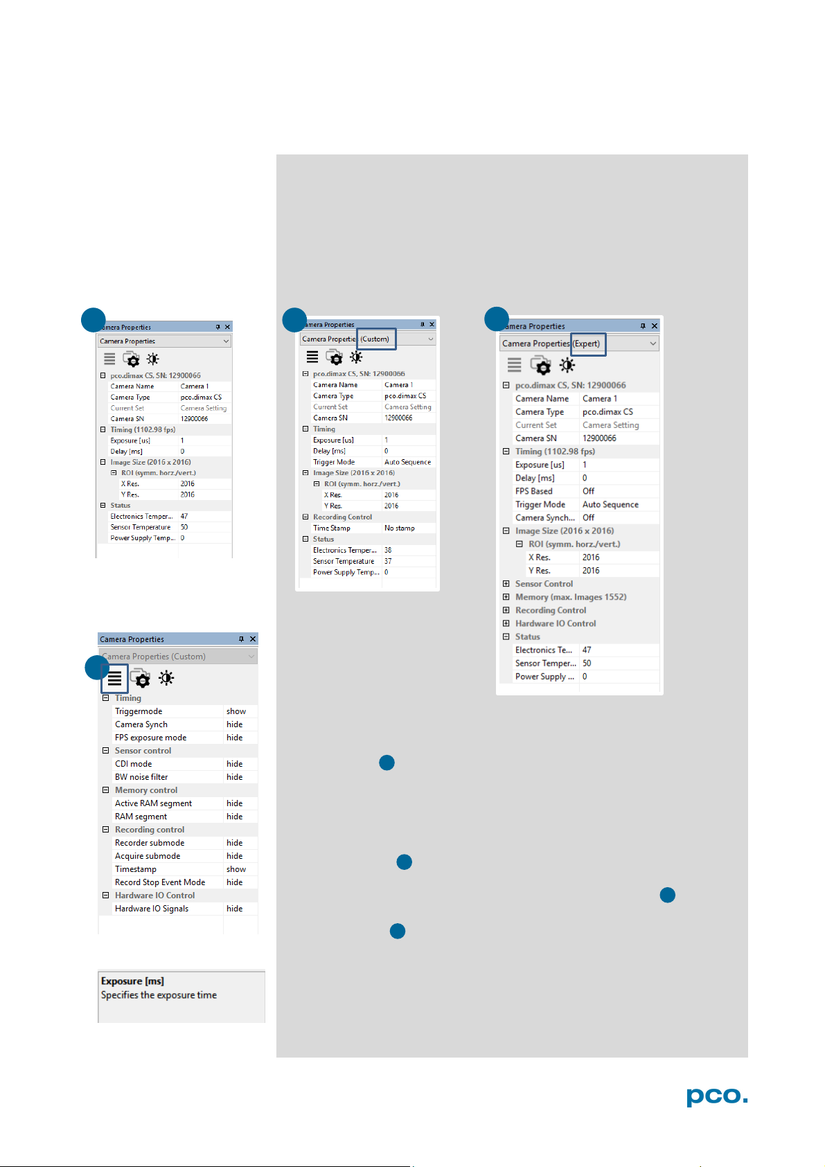
6.3 CAMERA PROPERTIES
The Camera Properties window in Camware is the main interface for
all camera settings. The active set in Camera list is adjusted here.
The former topic Camera Control (known from Camware 3.x) and
the Convert Control (see 6.3.8) can be opened additionally.
Three view options with various functions can be selected: Basic,
Custom and Expert.
Basic mode 1 only shows camera name, timing, image size and
status. In Basic Mode the frame rate is always calculated
automatically based on the selected exposure time, i.e. while
exposure time is increased, frame rate decreases. It is recommended
for Camware beginners.
Custom mode shows several more setting possibilities and
functions are hidden or shown by the Custom Properties Button.
Beside the Basic mode many more options are selectable.
Expert mode (for advanced users) shows all possible camera
feature settings.
An explanation for every feature is displayed below the properties
dialog.
17
Rxposure
n
Readout
n + 1
n + 2
n
n + 1
n + 2
t
t
NOTE
Exposure
n
n + 1
n
n + 1
n - 1
t
t
1
6.3.1 TIMING
General Information
The most important parameter for a high-speed camera is the
frame rate. The upper limit of the frame rate is defined by the
exposure time and the readout time.
In this context trigger means exposure trigger, i.e. the trigger
signal controls the exposure of a single image.
Exposure and readout of one image are done simultaneously,
i.e. while image n is being read out from the sensor, image n+1
is already integrated within the sensor’s pixel.
Readout time correlates with the resolution: if you select a
smaller resolution (fewer rows and columns) the readout time is
also reduced.
In case of short exposure times, the readout time is the limiting
factor, i.e. a new image can only be recorded, if the previous image
has been read out.
For long exposure times, the exposure time is the limiting factor:
Readout
exp
readout
As the pco.dimax cs is
a high-speed camera,
triggering single images using the Soft
Trigger button will
result in a significantly
degraded image quality (noisy images).
exp
sys
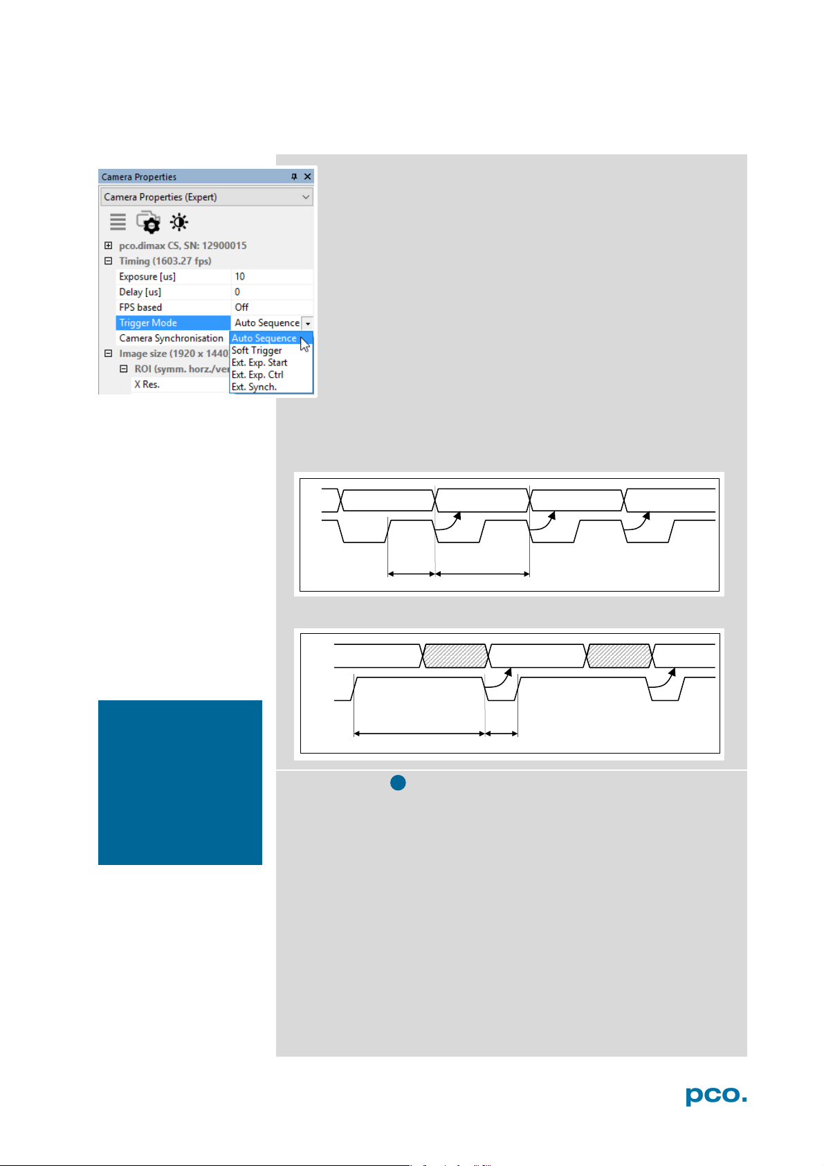
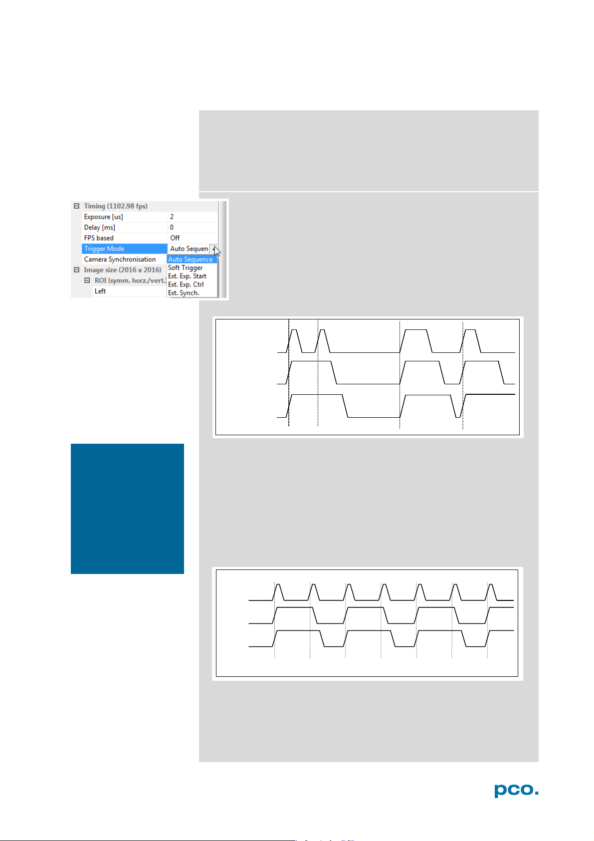
Trigger Modes
Auto Sequence: the camera optimizes the image recording to
achieve the best possible frame rate. In the Auto Sequence
Exposure Control mode, the camera he highest possible frame rate
against the set exposure time and the time required for a frame
readout. Upon a start command the sequential recording starts and
lasts until a stop command..
Software Trigger: single images are recorded by this Camware
command. A single image is acquired by pressing the Single Trigger
button. This button appears after pressing the Start Record button.
Other signals have no influence on this operating mode.
External Synchronization (BNC Sync In): the pco.dimax also uses
an external synchronization signal feeding a phase-locked loop (PLL)
in the camera.
18
6 CAMWARE 4 SOFTWARE
(difference <
random, whether or
BNC Sync In
Exp Trig Signal
BNC I/O
BNC I/O
accepted
accepted
acc.
not acc.
BNC I/O
acc.
not acc.
BNC Sync in
BNC I/O
acc.
not acc.
acc.
not acc.
acc.
Advantages of the PLL (Ext synch) solution:
• Availability: only for frequenc ies of 1, 10, 100 or 1000 Hz
• Reliability: in case of dropouts of the external synchronization signal, the
synchronization is kept internally by the PLL signal with only small d eviation.
• Noise immunity: interference on the signal is automatically detected and discarded.
• Flexibility: the cameras can even be set to different frame rates, as long as all
frame rates are an integer multiple of the synchronization frequency.
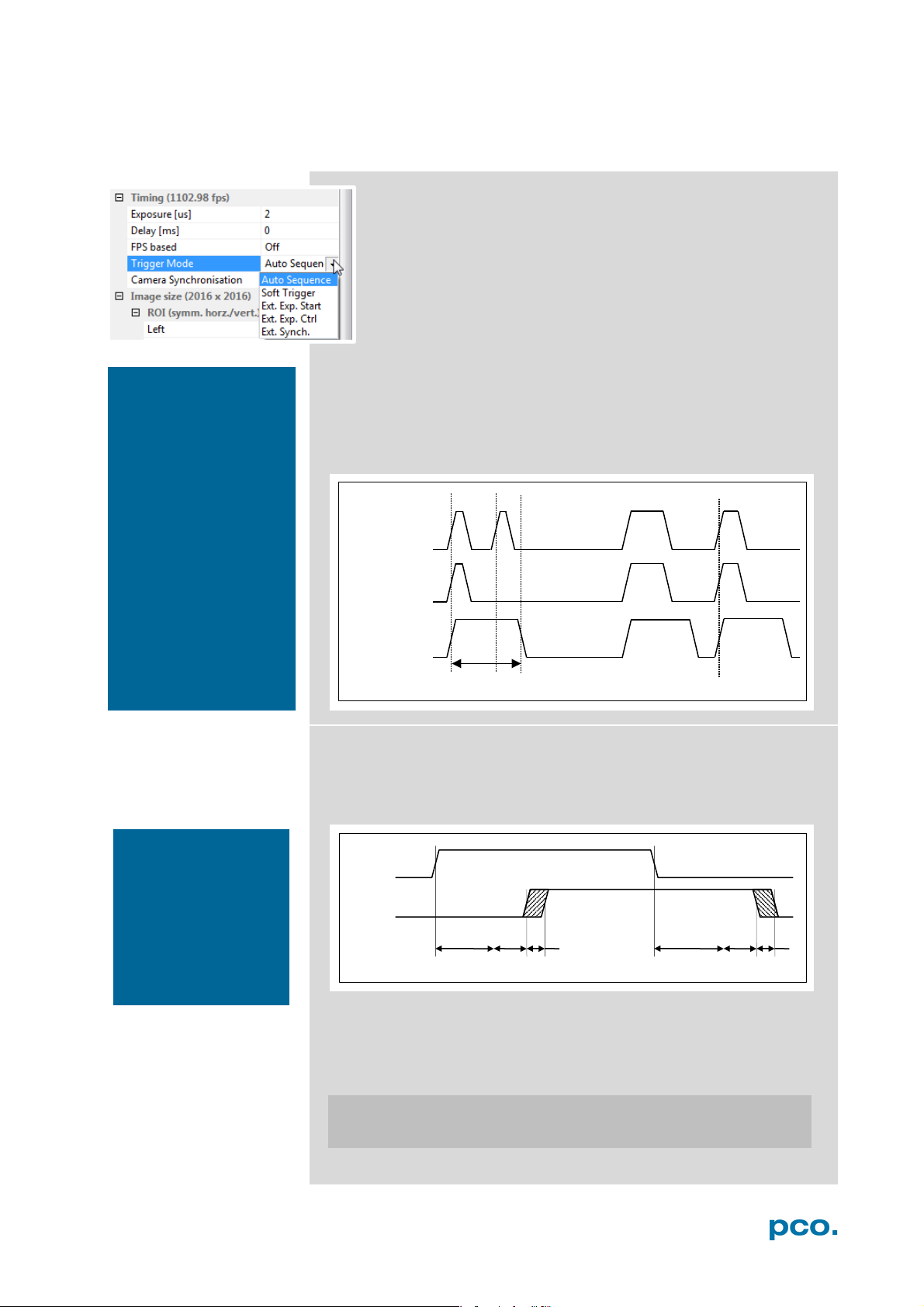
External Exposure Start (Ext. Exp. Start):
The image acquisition is triggered by an external signal. The
single trigger button acquires a single image for a test.
In Ext. Exp. Start exposure control mode, image acquisition
starts by the falling or rising edge of the signal at the BNC Sync
In input (see Appendix A1.2). The frame rate cannot be set, as
the frame rate is defined by the frequency of the external signal.
However the exposure time and ROI (Region of Interest)
settings affect the maximum possible frame rate.
NOTE
If the trigger rate of
the external signal is
very near the maximum possible frame
rate
1/1000), then it will be
not a trigger is accepted!
Exp Stat (out)
Busy Stat (out)
A new trigger is possible after t
readout
or (t
exp
+ t
) (whichever is longer)
sys
after the preceeding trigger. The Busy Status (BNC I/O) signal (see
chapter 6.3.6) indicates whether a new trigger is accepted. The
maximum achievable frame rate in External Trigger mode is
negligibly less (about 0.1%) than in Auto Sequence mode. If the
trigger rate of the external signal is higher than the maximum possible
frame rate, every second trigger pulse is ignored. Therefore the actual
frame rate drops to half of the external trigger rate. If the trigger rate
is increased further, then only every 3
rd
, every 4th etc. trigger edge will
be accepted.
Exp Trig Sig
Exp Stat (out)
Busy Stat (out)
In order to avoid trade-offs at maximum frame rate use either the
Busy Status signal BNC I/O (see chapter 6.3.7) or make sure the
external trigger rate follows this condition:
Ext. Trigger Rate ≤ f
/ 1.001.
max
19
NOTE
ware trigger. The
recommended for
quired!
t
-0 /+25ns t
configurable 0…1ms
rsys
fsys
t
Exposure
BNC Sync In
t
t
t
t
t
BNC Sync In
BNC I/O
BNC I/O
Busy Stat. (out)
t
accepted
accepted
acc.
not acc.
NOTE
from T0 Trigger and
should not be mixed
frames based on a
terminates the active
Sequence Trigger
Exposure trigger differs
up.
Exp. Trig. (BNC Sync
In) triggers single
falling / rising edge.
T0 Trigger (BNC Trig In)
recording with a single
signal edge and allows
to record a predefined
number of images after
T0 (see chapter
6.3.5
External Exposure Control (Ext. Exp. Ctrl):
An external signal applied to the exposure trigger input (BNC
Sync In see chapter 6.3.7), controls start and duration of the
exposure.
In trigger mode Ext. Exp. Ctrl a new exposure starts by the
falling or rising edge of the signal at the BNC Sync In input. The
exposure is finished when the opposite edge is detected. Thus
in this mode, the start as well as the length of the exposure time
can be externally controlled. No further settings can be made,
as the image timing is completely controlled by the exposure trigger
signal yet. There is a maximum exposure time. If the trigger pulse is
longer than 20ms, the integration will be stopped at 20ms.
A new trigger is possible after t
readout
or (t
exp
+ t
) (whichever is longer)
sys
following the preceding trigger. The Busy Status (BNC I/O) signal
(see chapter 6.3.7) indicates whether a new trigger is accepted.
Exp. Trig. Signal
Exp. Stat. (out)
readout
Mode).
There is no specified
timing for the soft-
software trigger is not
applications where an
exact timing is re-
Detailed Timing for External Exposure Start /Control
The detailed timing for external trigger includes system delay times,
an adjustable additional delay time and the jitter.
Exp. Trig. Signal
rsys
delay
jit
Parameters for the following tables:
• Width of the selected ROI must be a multiple of 24
• Data is not applicable in trigger mode External Exposure Start.
• Trigger edges occurring within t
+ 200ns after a previous
delay
trigger are ignored.
jit:
t
+ t
system delay times depending on ROI (see next page)
delay
fsys
delay
jit
20
6 CAMWARE 4 SOFTWARE
camera type
exposure time
delay time
pco.dimax cs
1.5 μs … 40 ms
2 μs … 40 ms
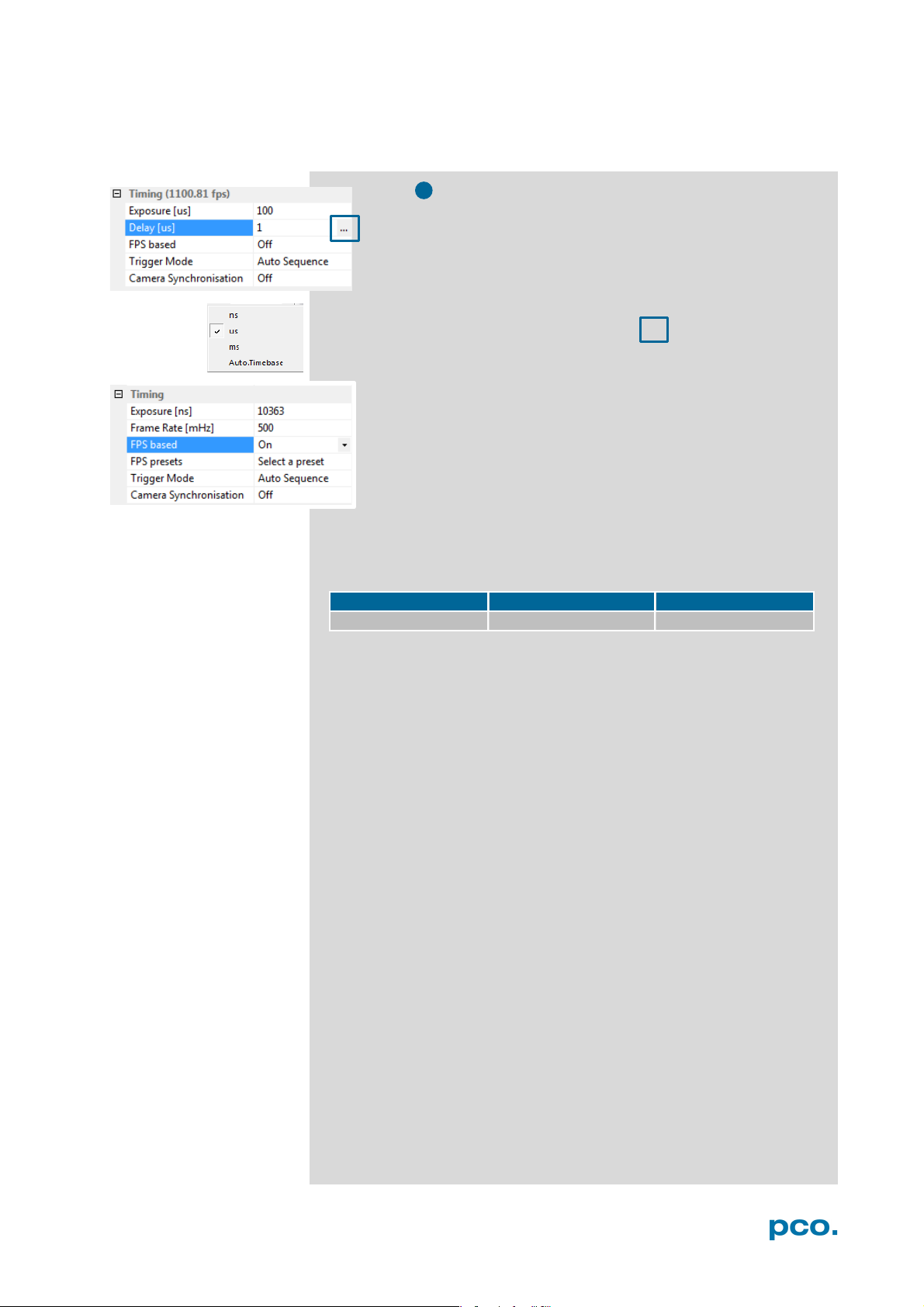
2
Timing
The exposure and delay time can be precisley set in steps of 1
μs. The effective stepsize depends on the operation mode.
The slider and the up/down control refer to the blue highlighted
unit. The resulting frame rate is derived from this setting. Delay
time setting is not recommended for high-speed applications.
Easily change time base by clicking on … and the respective
window opens.
FPS based: The camera optimizes the image recording to
achieve the selected frame rate. The exposure time is limited to
1/fps, lower values can be selected. (Selectable for Auto
Sequence trigger mode and preset for External synchronization
mode.)
First the frame rate is set. If the time required for readout of the image
is longer than 1 / frame rate, then the frame rate will be reduced to 1 /
readout.
t
If FPS based is selected and the selected exposure time requires a
lower frame rate, the exposure time will be cut to the maximum
possible time at that frame rate.
The minimum selectable frame rate is 0.465 Hz, but it only makes
sense to use: ≥ 20Hz.
21
increments horizontal:
24 pixel steps
increments vertical:
4 pixel steps
minimum ROI:
24 x 8 pixels
1
1 2 3
3
2
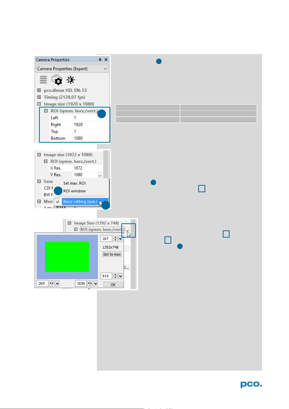
6.3.2 IMAGE SIZE
Region of Interest
To speed up frame rate and to save storage space, the ROI
(region of interest) selects only a part of the sensor to be read
out. Due to the sensor structure and readout electronics the
selectable region is always symmetric to the center.
pco.dimax cs
Basic Setting:
Activate Basic Setting by clicking on … to easily set a ROI by
just typing in the horizontal and vertical resolution in pixels.
ROI window
Select the ROI (symm. horz./vert.) menu and
activate ROI Window by clicking on ... or use the,
or use the … right to the X Res / Y Res and click
on ROI window.
The ROI window will open and it is possible to set a
new Region of Interest by dragging a window with
the mouse or by keying in the values.
22
6 CAMWARE 4 SOFTWARE
status expos
General timing for the double image mode
readout
image n, 1st exp.
wait
ttd
te1
te2
image n, 2nd exp.
tif
exp trig
image n+1,
1st exp.
t
te1: exposure 1 te2: exposure 2
readout
1 23
1
2
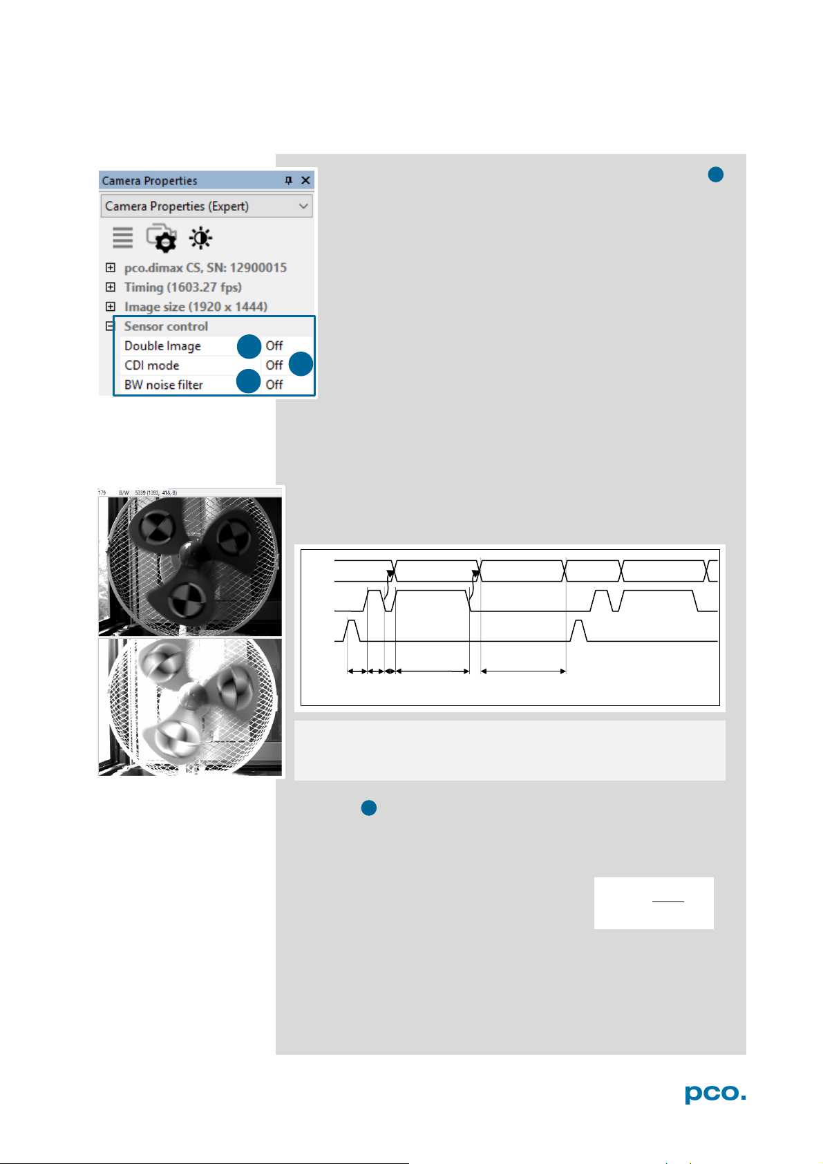
6.3.3 SENSOR CONTROL
Double Image / Double Shutter (only for monochrome sensors)
This feature is widely used for particle image velocimetry (PIV)
measurements and is an optional feature of the pco.dimax cs
series. The first exposure time t
the available range of the pco.dimax camera. The second
exposure time t
second exposure is the readout time of the first image. The
interframing time t
exposure #1 and start of exposure #2.
As can be seen the maximum frame rate of the double image
mode (where frame rate is defined as the frequency of the
double images) will drop to just half the value compared to the
standard mode.
The double image mode will work only in the trigger modes Auto
Sequence and External Exposure Start. See 6.3.1.
Note: to achieve a blur free second image the environment should be
kept dark and the exposure duration of the second image determined
by a flash light.
Timing Diagram for Auto Sequence
may be any exposure time of
e1
cannot be directly adjusted. The length of the
e2
denotes the transition time between end of
itf
readout
ttd: trigger delay time tid: intrinsic delay
tif: interframing time t
: readout time
CDI mode
The correlated double image (CDI) mode records images with
increased dynamic range and a 30% better performance on the weak
signal side of the images (at the expense of half of the usual frame
rate, because double images are acquired).
The min. exposure time is calculated as follows:
t
= min. exposure time
exp
= max. frame rate
f
CDI
Example:
resolution = 1920 x 1080 pixel; f
In this case t
To increase t
is both minimum and maximum exposure time.
exp
decrease frame rate or resolution.
exp
= 1067 fps → t
CDI
exp
= 467 μs
1
=
2∗
23
NOTE
l camera
recording activation
by software (press
4
3
1 2 3
1
2
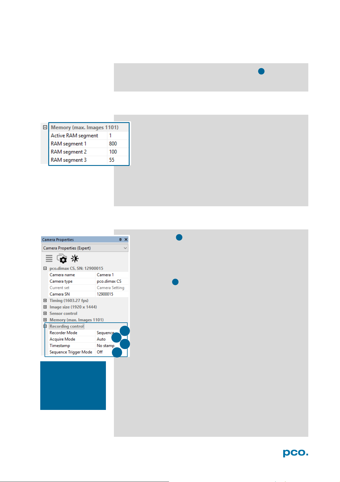
6.3.4 MEMORY
B/W Noise Filter (only available for pco.dimax cs b/w)
Intelligent spatial noise filter.
The Memory area controls the pco.dimax built-in memory.
The RAM has four segments. In Camware only three are usable
to save images. The fourth is used by Camware itself for internal
processes.
You may record into three different segments and to set the
exact number of images in each segment. Camware always shows
the maximum number of images (depending on RAM size and chosen
ROI).
Active RAM Segment: choose the active segment: 1, 2 or 3.
6.3.5 RECORDING CONTROL
Recorder Mode
In Sequence mode the camera stops after the memory (i.e. the
active RAM segment) is completely filled. In Ring Buffer mode
the camera records until it is stopped – overwriting the previous
images continuously.
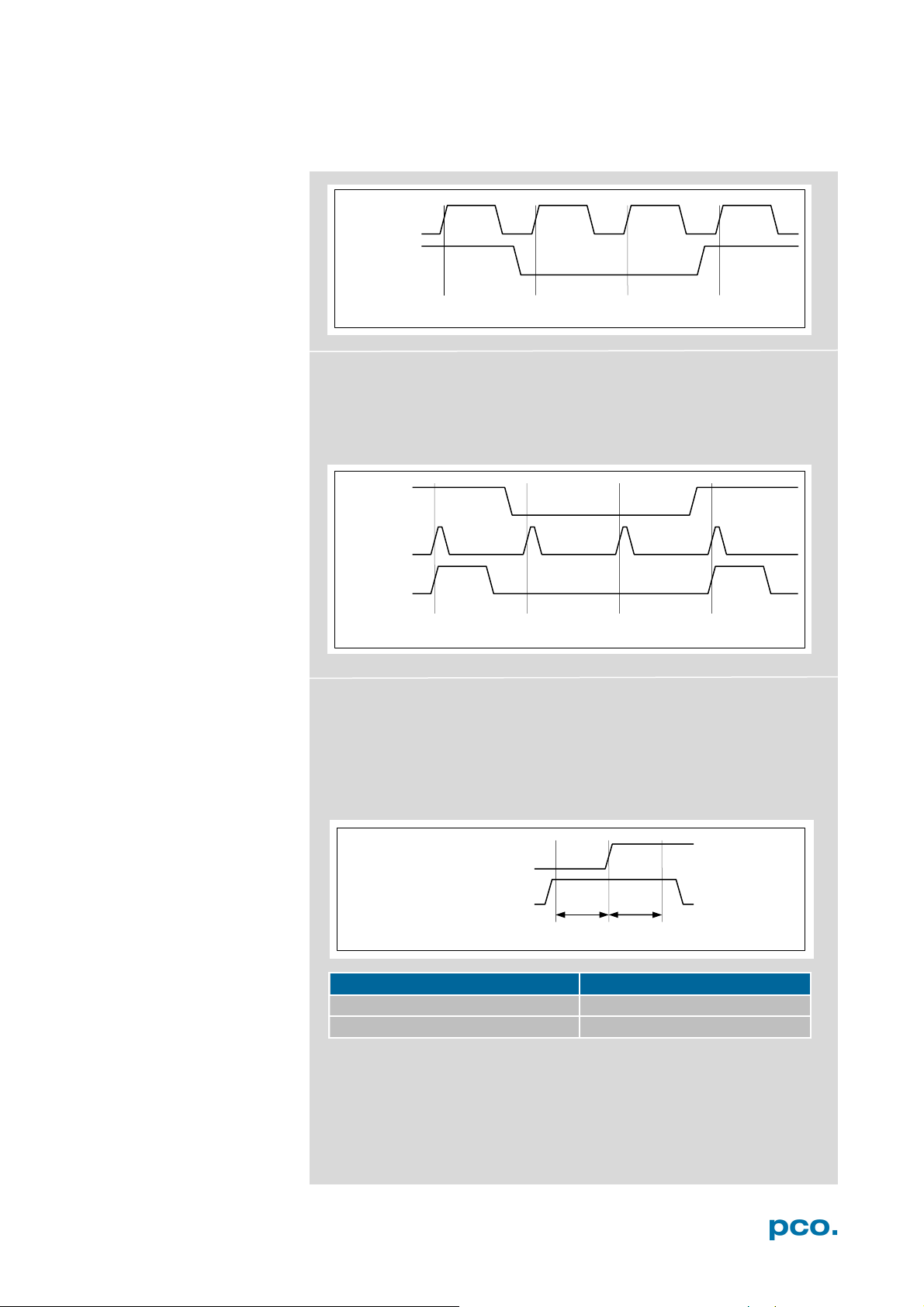
Acquire Mode
The Acquire Mode enables or disables the recording by an
external signal.
If set to Auto all images are accepted and all images taken are
saved. A signal at the BNC Trig In input (see 6.3.6) is ignored
when set to Auto.
If set to External, the camera only records images, when the
external signal applies.
Acquire mode still requires initia
record button)!
The signal at the BNC Trig In input does not affect the sensor's timing
scheme.
The BNC Trig In is sampled at the beginning of the exposure, shown
by the rising edge of the exposure status (BNC I/O) output.
BNC Trig In input high: (low, when inverted): image saved to
memory
BNC Trig In input low (high, when inverted): image lost (not saved
to memory)
24
6 CAMWARE 4 SOFTWARE
pco.dimax model cs
tsu
60 ns
BNC Trig In
BNC Sync In
tsu
th
BNC Trig In
BNC I/O
accepted
not acc.
not acc.
accepted
BNC Sync In
BNC Trig In
BNC I/O
saved
not saved
not saved
saved
Exp Stat (out)
In trigger mode External Exp. Start, the BNC Trig In input acts as a
gate for the trigger signal. A rising trigger edge (rising, falling when
BNC Sync In is inverted) is accepted only when the BNC Trig In
signal is high (low, when inverted).
Exp Trig (in)
Exp Stat (out)
In trigger mode External Exp. Ctrl, the BNC Trig In input works very
similar to the mode External Exp. Start. However, the BNC Trig In
input is ignored for the edge which is closing the exposure time (an
already started exposure will be finished).
When using BNC Trig In in external trigger modes, the following
timing specification should be met:
Exp Trig (in)
Acq Enbl (in)
th 60 ns
If the BNC Trig In signal changes within the window of tsu (set up) to
t
h
ignored.
(hold), the behavior is random. The trigger may be accepted or
25
3
BNC Trig In
Record State
1
Exposure
2 4 3 5 6 7 8 9 10
Stop Event / T0 Trigger
4
Delay Images = 10
4
1 2 3
1
2
3
3
NOTE
sure signal polarity is
type at the acquire
enable (BNC Trig In)
input) for TTL signal
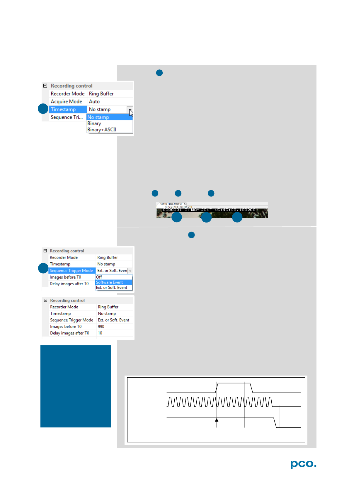
Timestamp
A time stamp can be placed into the upper left corner of the
image. It can be either set to no stamp, binary or binary with
text. The time resolution is 1 μs.
In binary mode the first 16 pixels will be filled with the time
stamp information (binary code). The numbers are coded in
binary coded decimal (BCD) with one byte per pixel. Every pixel
contains two digits. If the pixels have higher resolution than 8
bits, then the BCD digits are right bound adjusted and the upper bits
are zero. For further information refer to the SDK manual.
In binary and ASCII mode text will be placed into the image its
content (271x 8 pixels).
The timestamp shows the end of the exposure time.
Three different information is stamped onto the image: number of
the image , date and time .
When using the
Extension box make
inverted to a TTL signal
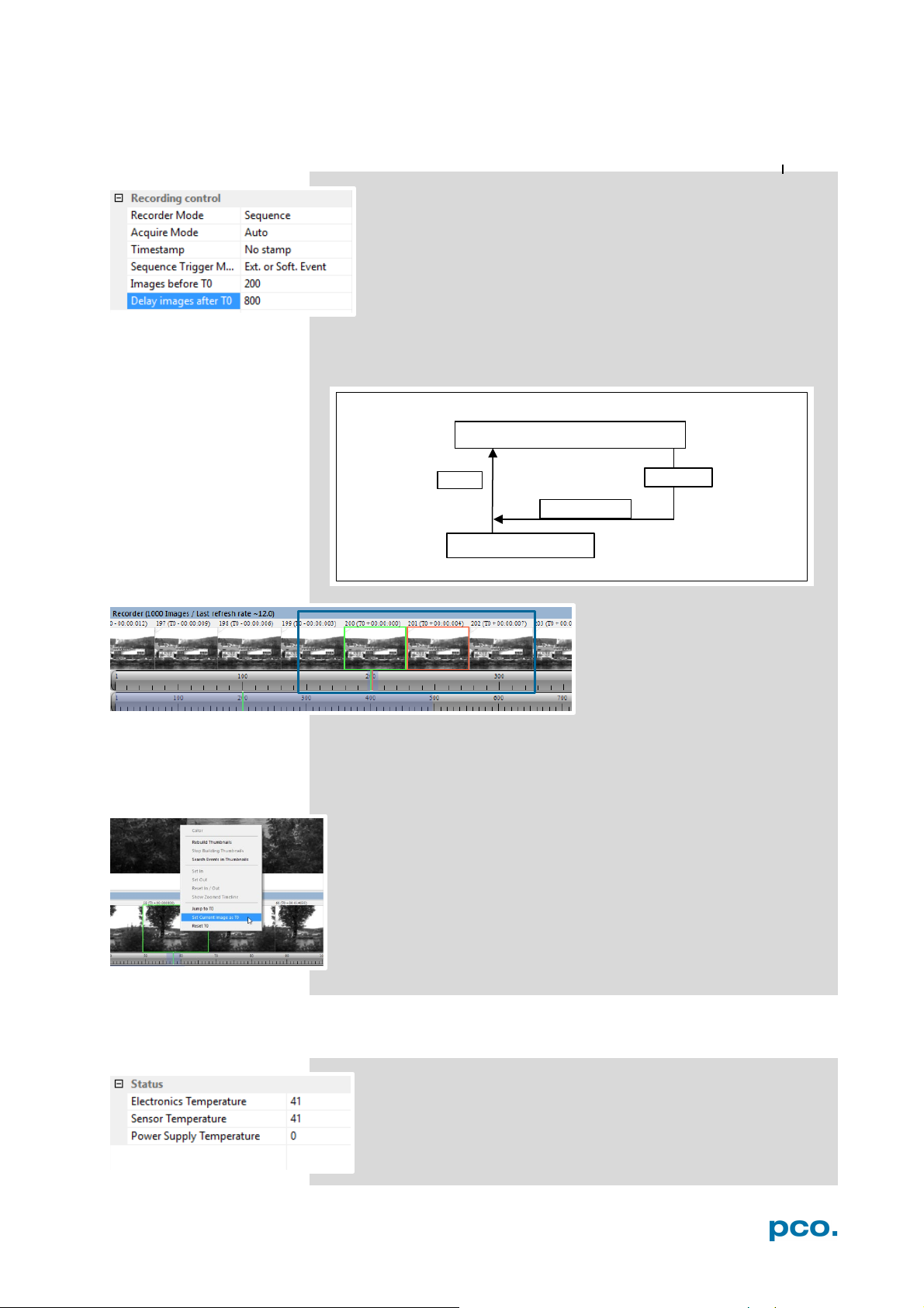
Sequence Trigger Mode
The Sequence Trigger Mode enables the user to stop
capturing a sequence of images via an external signal, so called
T0 trigger. The user can set the number of images before and
after the trigger event.
Since the Sequence Trigger Mode uses the BNC Trig In input
(see chapter 6.3.6), the acquire function cannot be used. The
acquire mode thus has to be set to Auto.
The camera already records images into the selected RAM and
may have filled it completely before the Sequence Trigger
Mode starts. Therefore the recorder mode should be set to
Ring Buffer.
Off: function is not active; signal at BNC Trig In does not stop
the record.
Software Event: only a software command can stop the sequence.
Ext. or Soft. Event: both, a signal edge at BNC Trig In or a software
command can stop the sequence.
input. (Trig In BNC
type.
26
6 CAMWARE 4 SOFTWARE
800 images
RAM 1000 images
stop event /T0 Trigger
#1000
Delay Images = 800 (80%)
The relative position of the T0 trigger within the recorded
time window depends on the size of the RAM segment and
the delay images parameter. The following figure shows an
example, where the buffer size is 1000 images: The position
of the trigger is always calculated backwards from the end of
the buffer. The relation is always in terms of images.
In this context T0 is the point at which the sequence trigger is set
(at the BNC Trig In input).
After recording is finished
Recorder Images (see chapter
6.7) shows the thumbnail
images of the last recording:
Image T0 is framed in green,
the currently selected image in
All images before and after T0 are specifically marked, e.g. with 202
(T0 + 00:00:007). 202, in this case, corresponds to the image number
and its recording point in time after T0. The time stamp is divided into
min : s : ms.
Additional possibility to define T0: Right-click into the thumbnails
and Set Current Image as T0. Reset T0 erases this manually set
T0.
All Recorder Images features see 6.7.
orange.
6.3.6 STATUS
Shows the current temperature level of the pco.dimax cs
camera.
27
 Loading...