

Page 1

76433 Issue 2
www.pclairtechnology.com
D90/91/92/93 Tyre Inflator Quick Start Manual
Safety Guidelines
This manual contains information that is very important to know
and understand. This information is provided for safety and to
prevent equipment problems. To help recognise this information,
observe the following symbols.
Danger indicates an imminently hazardous
situation which if not avoided WILL result
in death or serious injury.
Warning indicates a potentially hazardous
situation which if not avoided, COULD
result in death or serious injury.
Caution indicates a potentially minor or
moderate injury.
Notice indicates important information,
that if not followed, may cause damage to
equipment.
Unpacking
After unpacking the unit, inspect carefully for any damage that
may have occurred during transit.
Do not operate unit if damaged during
shipping, handling or use.
General Safety Information
The operator of this product must take the necessary precautions
to prevent the level of danger indicated by these symbols. The
operator is required to read and understand this instruction
manual and all safety warnings, labels etc.
Any employer allowing the use of this product in their field of work
must distribute this instruction manual to all users. The employer
must also ensure all users read, understand and follow the
instructions as described in the manual, safety warnings, labels,
etc.
Please read and save these instructions. Read carefully before attempting to assemble, install, operate or maintain the product described.
Protect yourself and others by observing all safety information. Failure to comply with instructions could result in personal injury and/or
property damage! Retain instructions for future reference.
Purchased airtower may not be representative of the image shown
Read and understand all safety warnings
and instructions before operating this
product. Failure to read and follow all
safety warnings may result in serious
personnel injury or death. Property
damage and/or product damage may also
occur if all warnings are not followed.
1. Do not expose the product to flammable gases,
vapours or fumes
2. Do not store flammable gases in or near this product
3. Never use flammable or toxic solvents to clean the
product or any of the unit's parts
4. Never remove or alter any safety warning labels, tags,
etc. located or provided with product.
5. Follow all directions for maintenance.
The use of other than genuine PCL
replacement parts may result in reduced
equipment performance. Repairs must be
performed by authorised repair personnel,
otherwise the warranty will be void.
PART NUMBER
SERIAL NUMBER
Page 2
PCL D90 series Tyre Inflator
www.pclairtechnology.com
General Specifications
D90 and D91
Max inlet supply: 218 psi / 15 bar / 1500 kPa
Recommended supply : 10 psi / 0.7 bar / 70 kPa
above the max set pressure of Inflator
D92 and D93 optional internal 7 or 10 bar compressor
Max operating pressure : 145 psi / 10 bar / 1000kPa (10 bar)
Max operating pressure : 80 psi / 5-50 bar / 550kPa (7 bar)
Min operating pressure: 4 psi / 0.3 bar / 30 kPa
Display resolution: 1 psi / 0.1 bar / 10 kPa
Units of measurement: psi / bar / kPa / kg/cm
Electrical Installation
In order to provide a trouble free operation it is necessary to
connect the power supply from the main switchboard with a MAX
3amp fuse/RCB protection device. This must be grounded.
The circuit breaker should be marked as the disconnecting device
for the equipment.
Inside installations
Use 3 pin connecting plugs or 2 pin + Earth with the Earth Ground
wire installed on electrical infrastructure. This must be grounded.
Outdoor installations
The unit must be connected to an earth conductor or conducting
metal work (metal pipe conduit or sheathing) which has
equipotential bonding to the main Earthing point of the installation.
The unit is designed to run with the earth connection installed.
"According to Class 1 - Basic insulation in conjunction with
protective Earthing"
Air installation
For models D90 and D91 only
The compressor producing the air should have the necessary
water and dirt filtration, to minimise accumulation of debris at the
inflator line filter strainer.
For efficient tyre inflation, ensure that the air supply is 10 psi, 0.7
bar or 70kPa above the intended maximum inflation range.
Air supply port
R1/4
Electrical supply
ST-18 Socket
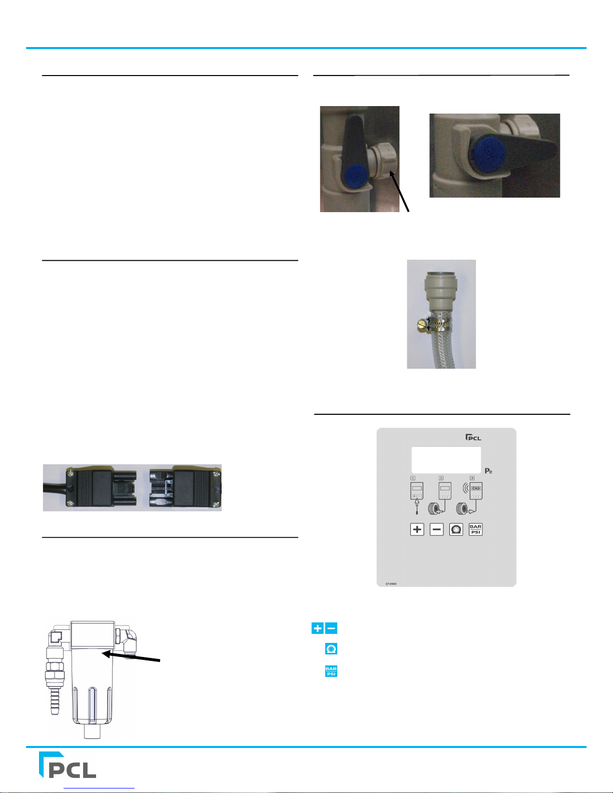
Control Panel
Key Legend
Increase or decrease to set pressure
Start flat tyre inflation
Switch pressure unit
Note:
Key legend above is for standard PCL decal, symbols used may
vary by individual part number but functionality remains the same
Water installation (optional)
For models D91 and D93 ensure that 15mm piping is available to
connect to the water supply port.
Water supply port
(where fitted) 15mm
tubing/pipe
Stop valve
On position
Stop valve
Off position
Double check valve
(anti syphon)
Page 3

PCL D90 series Tyre Inflator
www.pclairtechnology.com
Start-up
1. Turn on power supply via the isolator switch.
2. Display will show all LCD digits check
3. Display will show the current Firmware version number e.g.
'3.2.1'
4. Display will show Program model variant '300' ( psi default)
or '302' (bar default)
5. Display will show the application, 'Std'
6. After 10 seconds the display will show 'PCL'
7. The unit will then display the set default pressure
Do not connect the hose to the tyre during start-up or E5
will show
Standard Operation
Inflation and deflation
1. Set desired pressure, by touching either or
2. Connect the hose to the tyre.
3. Automatic inflation will commence to the set pressure,
periodically stopping to display the pressure of the tyre.
4. If the pressure in the tyre is below 3 psi, 0.2 bar or 20 kPa,
the process will not commence until is touched.
5. When the Set pressure is reached, the buzzer will sound
and the display will show 'END' with the final pressure.
6. Remove the hose from tyre.
7. For selection of alternative pressure unit touch .
For adjustments to Inflators parameters
please refer to your Distributor or PCL.
This unit is not suitable for the filling of
bicycle tyres with a standard (Presta,
Woods) bicycle valves and adapters. Over
fill of the tyre is possible!
User Inspection mode
It is possible to set the inflator to act as a pressure gauge.
The display resolution is changed and can be used to reference the
inflator against a calibrated pressure source. The inflator automatic
cycle is inhibited.
To access:-
1. Touch and together
2. The unit will beep but the display will not change
3. Touch 5 times
(if this is not undertaken within 10 seconds, the Inflator
reverts back to normal Inflator mode)
4. Display will show the pressures to the minimum resolution:
psi = 0.1 / Bar = 0.01 / kPa = 1 / kg/cm = 0.01
5. Connect the hose to the tyre and the display will show the
pressure in the tyre
6. When complete, touch any button to return to the last set
mode.
Isolator switch
The isolator can be turned off by simply turning the
switch clockwise or anti-clockwise.
There is a 10amp fuse installed inside the isolator
switch.
Coin mech (Optional)
1. Use the keys provided to open the door.
2. Take the coin mech holder out from underneath the
coin mech and empty the contents.
3. Re-attach the holder and lock the doors.
Page 4

PCL D90 series Tyre Inflator
www.pclairtechnology.com
Template for mounting the airtower to the floor.
Page 5

PCL D90 series Tyre Inflator
www.pclairtechnology.com
Service/Maintenance
There is no requirement to service the following items:
1. Pressure Transducer
2. Electric Control Board
If these are faulty they can only be
replaced by a competent person.
Please refer to an Authorised
dealer.
Periodically
Check the hose.
Check the tyre connector.
Remove air input supply and tyre hose from the head.
Unscrew captive sintered filters from filter housings and
clean or replace.
Working safety instructions
Since the unit is not explosion-proof, the device should not be
installed in areas where explosions are possible. Consideration
must be given to the requirements relative to Hazardous Area
Standards for your region or country.
The unit is designed and built to the relevant basic health and
safety requirements of the EC.
This product can be dangerous if used
improperly. Children should not be
allowed to use this equipment, as
incorrect setting can allow tyre to be
over inflated and a subsequent tyre
burst/explosion can occur!
Each person who is involved with installation, start-up,
maintenance and the operation of the unit must read and
understand the complete operating manual.
The PCL tyre inflators are exclusively approved for the
dispensing of air/N2. Each use which doesn't follow this
purpose as well as modifications to the product will be
deemed to be improper use. The manufacturer is not
liable for damages caused by improper use, the risk lies
solely with the user.
Proper use of the product also implies the
observance of the manufacturers
instructions with regard to installation,
start-up, operation and maintenance.
All works concerning installation, start-up,
adjustment and maintenance must be
made by qualified staff. For the operation
of this tyre pressure inflator the local
safety and accident prevention rules must
be observed in all cases.
High Pressure air is stored within the
system.
When using N2P mode , locate this system
in a well ventilated area. Position the
system away from any heat source.
Do not exceed the maximum air input
pressure.
Do not operate this product if tired or
under the influence of medication, drugs
or alcohol.
To avoid the risk of personal injury,
especially to the eyes, face or skin DO
NOT direct the air/N2 stream at any
person.
Page 6

PCL D90 series Tyre Inflator
www.pclairtechnology.com
Problem Possible Cause Solution
No display No power connected Switch power on
No inflation process Tyre is below 3 psi
Faulty connector
Press flat tyre button
Replace faulty connector
Buzzer does not sound Buzzer volume has been turned off
Buzzer is damaged
Turn buzzer on or
Replace buzzer
Inflation process starts but does
not complete
Low or no supply pressure
Leaks exist
Check supply pressure
Confirm leaks do not exist
Supply pressure leaks out input Input and tyre hoses are incorrectly reversed Ensure input connection is to offset port, tyre
connection is central between input and exhaust
Inflating or deflating is very slow Check that mesh filters under input and output
port fittings are blocked
Clean and or replace mesh filters
Connector will not seal to the
tyre stems
Connector worn Replace connector
Connector leak while not
connected to tyres
Connector worn Replace connector
No power to display head Isolator fuse blown Replace 10 amp isolator fuse
E1 Unstable or insufficient supply pressure Check the supply pressure
E4 Small volume, caused inflator to check pressure
> 2bar / 29psi over target pressure
Check hose is not kinked or blocked, ensure a OPEN
END connector is installed
E5 Inflator started under pressure i.e. is connected
to tyre or a CLOSED END connector is being used
Remove hose from tyre and allow inflator to reset
Change connector to OPEN END type
E6 Pressure sensor drift out New sensor required - Refer to authorised repairer
E8 Pressure sensor disconnected from PCB or faulty New sensor required - Refer to authorised repairer
E9 Pressure sensor failure - high New sensor required - Refer to authorised repairer
E10 Under voltage Check power supply
E11 Over voltage Check power supply - Refer to authorised repairer
E12 Checksum corrupted New PCB required - Refer to authorised repairer
E13 Lost or corrupted calibration settings New PCB required - Refer to authorised repairer
E16 Unit started under pressure Unit started when connected to a tyre or new sensor
required - Refer to authorised repairer
E17 Calibration settings corrupt Recalibrate unit - Refer to authorised repairer
E18 Runtime error New PCB required - Refer to authorised repairer
E19 Touch screen error New PCB required - Refer to authorised repairer
E20 - E23 Startup sequence error(s) New PCB required - Refer to authorised repairer
Trouble Shooting Guide/Error Messages
Page 7

PCL D90 series Tyre Inflator
www.pclairtechnology.com
PCL LIMITED WARRANTY
PCL warrants the components of each unit to which this Limited Warranty applies against defects in materials and workmanship for
a period of twelve (12) months from date of sale (as evidenced by bill of sale or equivalent) or for a period of eighteen (18) months
from date of shipment from PCL manufacturing facility (identifiable by the serial number and noted on original bill of lading from
the manufacturing facility), whichever period is shorter. During this warranty period and subject to the conditions set forth in this
statement, PCL will, at its option, repair or replace component parts that were defective at the time of shipment from PCL
manufacturing facility, subject, however, to the following specific EXCLUSIONS: hoses and connections.
Repair or replacement will not extend the warranty period.
Customer must give PCL timely notice of any warranty claim by contacting an authorized PCL service centre. Claims must be
accompanied by (1) evidence, by a bill of sale or equivalent, which clearly establishes date of purchase of the unit and (2) the
serial number, found on the unit. Customers must properly pack parts in their original or equivalent packaging, prepay shipping
charges, and insure the shipment or accept the risk for loss or damage in shipment. Return shipment to customer will be freight
collect unless otherwise agreed. For service at a customers location, customer will be charged the then prevailing service rates .
The Limited Warranty applies to PCL manufactured units only. Items listed in the applicable operators manual under routine
maintenance are not covered by this or any other warranty. Failure to complete maintenance as stated in any applicable
maintenance schedule will void the Limited Warranty. The Limited Warranty is expressly conditioned upon proper and normal use
and service of the unit and upon strict compliance by customer with all of PCL instructions and recommendations for installation,
operation and maintenance. The Limited Warranty does not apply to the unit or parts that are damaged or become defective due to
improper handling, maintenance, storage, use, or operation, and does not cover ordinary wear and tear, corrosion, or erosion.
THE LIMITED WARRANTY SET FORTH IN THIS STATEMENT CONSTITUTES PCL'S SOLE WARRANTY FOR THE UNIT AND
THE REMEDIES SET FORTH HEREIN CONSTITUTE CUSTOMERS SOLE REMEDIES FOR BREACH OF WARRANTY. THIS
LIMITED WARRANTY IS IN LIEU OF ALL OTHER WARRANTIES, EXPRESS OR IMPLIED, IN FACT OR BY LAW,
INCLUDING WITHOUT LIMITING THE GENERALITY OF THE FOREGOING, ANY WARRANTY OR MERCHANTABILITY OR
FITNESS FOR A PARTICULAR PURPOSE.
Determination of the suitability of the unit for the use contemplated by the customer is the sole responsibility of the customer. PCL
shall not, under any circumstances, be liable in contract, tort or otherwise (including negligence and strict liability) for indirect,
special, incidental, or consequential damages, and PCL's total liability shall not exceed the net purchase price for the unit. PCL shall
be excused for delay or inability to perform obligations due to events beyond its reasonable control.
CUT HERE
Mail
Warranty Department
PCL
Holbrook Rise
Holbrook Industrial Estate
Sheffield
S20 3GE
United Kingdom
Warranty Registration
Please complete and mail this form to activate warranty
Or visit us at www.pclairtechnology.com
Name ________________________________________ Title __________
Company Name _______________________________________________
Type of Business ______________________________________________
Address _____________________________________________________
City ______________ County _______________ Post Code __________
Telephone ___________________________________________________
Part Number ____________________ Serial No _____________________
Purchased From _______________________________________________
Purchase Date __________________________
Page 8

Calibration Certificate
Each unit, before release, is checked and calibrated on test equipment that has accuracy
traceable to Druck pressure indicator S/N2329290.
The Druck unit is referenced to Certificate 0029346 issued by UKAS Laboratory No. 0221.
This accuracy exceeds BS EN 12645:2014 (MPE = 0.08 bar).
READING ACTUAL SET PRESSURE
1 BAR PSI KPA
2 BAR PSI KPA
PART NUMBER
SERIAL NUMBER
TESTED BY
DATE
Declaration of conformity
Note : The declaration of conformity is valid for units operating at 230V/50Hz.
2014/30/EC (EMC directive) confirmed by report No.10654/TR/1
2006/95/EC (LOW Voltage Directive)
National regulations of Germany (PTB), France (LNE), Spain (CEM) and Portugal (IPQ)
Mark McCaughey
Technical Director on behalf of PCL
 Loading...