

pcl A10, A20 Quick Start Manual
76387 Issue 2
www.pclairtechnology.com
A10 / A20 Inflator Quick Start Manual
Safety Guidelines
This manual contains information that is very important to know
and understand. This information is provided for safety and to
prevent equipment problems. To help recognise this information,
observe the following symbols.
Danger indicates an imminently hazardous
situation which if not avoided WILL result
in death or serious injury.
Warning indicates a potentially hazardous
situation which if not avoided, COULD
result in death or serious injury.
Caution indicates a potentially minor or
moderate injury.
Notice indicates important information,
that if not followed, may cause damage to
equipment.
Unpacking
After unpacking the unit, inspect carefully for any damage that
may have occurred during transit.
Do not operate unit if damaged during
shipping, handling or use.
General Safety Information
The operator of this product must take the necessary precautions
to prevent the level of danger indicated by these symbols. The
operator is required to read and understand this instruction
manual and all safety warnings, labels etc.
Any employer allowing the use of this product in their field of work
must distribute this instruction manual to all users. The employer
must also ensure all users read, understand and follow the
instructions as described in the manual, safety warnings, labels,
etc.
Please read and save these instructions. Read carefully before attempting to assemble, install, operate or maintain the product described.
Protect yourself and others by observing all safety information. Failure to comply with instructions could result in personal injury and/or
property damage! Retain instructions for future reference.
Read and understand all safety warnings
and instructions before operating this
product. Failure to read and follow all
safety warnings may result in serious
personnel injury or death. Property
damage and/or product damage may also
occur if all warnings are not followed.
1. Do not expose the product to flammable gases,
vapours or fumes
2. Do not store flammable gases in or near this product
3. Never use flammable or toxic solvents to clean the
product or any of the unit's parts
4. Never remove or alter any safety warning labels, tags,
etc. located or provided with product.
5. Follow all directions for maintenance.
The use of other than genuine PCL
replacement parts may result in reduced
equipment performance. Repairs must be
performed by authorised repair personnel,
otherwise the warranty will be void.
PART NUMBER
SERIAL NUMBER
Image shown is PCL standard decal.
Actual decal may vary by individual part number.

PCL ACCURA A10 / A20 Tyre Inflator
www.pclairtechnology.com
General Specifications
Max inlet supply: 218 psi / 15 bar / 1500 kPa
Recommended supply: 10 psi / 0.7 bar / 70 kPa
above the max set pressure of Inflator
Max operating pressure: 145 psi / 10 bar / 1000 kPa
Min operating pressure: 4 psi / 0.3 bar / 30 kPa
Display resolution: 1 psi / 0.1 bar / 10 kPa
Units of measurement: psi / bar / kPa / kg/cm
This Equipment also complies with the EC directives:
2004/108/EC (EMC directive)
confirmed by report No.10655/TR/1
73/23/EEC (LOW Voltage Directive)
as amended by 93/68/EEC
Accordance with IEC/EN 61010-1:2001 confirmed by
report No. TTR-004115-18-00
Installation
In order to provide a trouble free operation it is necessary to
connect the power supply from the main switchboard with a MAX
3amp fuse/RCB protection device. This must be grounded.
The circuit breaker should be marked as the disconnecting device
for the equipment.
The recommended supply line materials are copper or galvanised
steel tube and it is important that the line is blown out thoroughly,
to remove any foreign matter, before connection is made to the
unit.
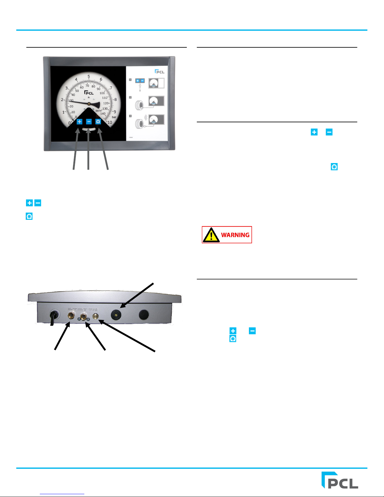
Air Supply Connection
Wall Mounted Unit - G 1/4 female thread..
Pedestal Mounted Unit - G 3/8 male thread
The compressor producing the air should have the necessary
water and dirt filtration, to minimise accumulation of debris at the
inflator line filter strainer.
For efficient tyre inflation, ensure that the air supply is 10 psi, 0.7
bar or 70kpa above the intended maximum inflation range.
Wall Mounted unit
When attached to a wall or other structure the unit must be surely
fixed by the means of 4 screws (mounting footprint can be found
on page 4)
Pedestal unit
This unit must be securely fixed to the floor by the means of 4
screws, running the air supply through the centre of the upright
post (mounting footprint can be found on page 4)
Inside installations
Use 3 pin connecting plugs or 2 pin + Earth with the Earth Ground
wire installed on electrical infrastructure.
Outdoor installations
The unit can be connected to an earth conductor or conducting
metal work (metal pipe conduit or sheathing) which has equipotential bonding to the main Earthing point of the installation.
The unit is designed to run with the earth connection installed.
"According to Class 1 - Basic insulation in conjunction with
protective Earthing"
Calibration & Accuracy
The accuracy of our digital units when released from our factory is
that:-
The maximum permissible error (MPE) = 0.08 bar
Each unit, before release, is checked and calibrated on test
equipment that has accuracy traceable to a UKAS Laboratory No.
0221 referenced to certificate 0029346.
PCL ACCURA A10 / A20 Tyre Inflator
www.pclairtechnology.com
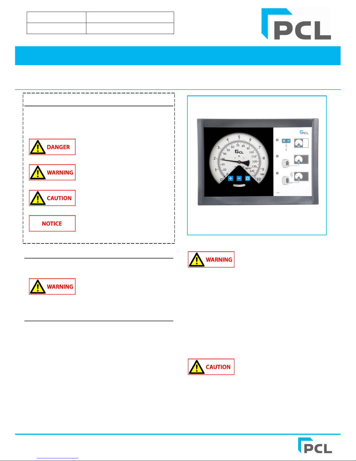
Control Panel
Key Legend
Increase or decrease to set pressure in all modes
Start flat tyre inflation, or below 3psi / 0.2bar / 20kpa
Note:
Key legend above is for standard PCL decal, symbols used may
vary by individual part number but functionality remains the same.
3 user touch type buttons
Start-up
After services connection to the unit ensure the following:
1. For efficient tyre inflation ensure that the maximum air
supply is 10 psi or 0.7 bar above the intended maximum
inflation range
2. The unit will open for a very short time one deflate pulse
before returning to the SET default pressure. Do not
connect hose to tyre during start-up or Error 3 will show.
Standard Operation
Inflation and deflation
1. Set desired pressure, by touching either or
2. Connect the hose to the tyre.
3. Automatic inflation will commence to the set pressure,
periodically stopping to indicate the pressure of the tyre.
4. If the pressure in the tyre is below 3psi, 0.2bar or
20kpa, the process will not commence until is
touched.
5. When the Set pressure is reached, the buzzer will sound
and the final tyre pressure displayed.
6. Remove the hose from tyre.
For adjustments to Inflators parameters
please refer to your Distributor or PCL.
This unit is not suitable for the filling of
bicycle tyres with a standard (Presta,
Woods) bicycle valves and adapters. Over
fill of the tyre is possible!
User Inspection mode
It is possible to set the inflator to act as a pressure gauge.
The display resolution is changed and can be used to reference the
inflator against a calibrated pressure source. The inflator automatic
cycle is inhibited.
To access:-
1. Touch and together
2. Touch 5 times
(if this is not undertaken within 10 seconds, the Inflator
reverts back to normal Inflator mode)
3. Display will show the pressures to the minimum resolution:
psi = 0.1 / Bar = 0.01 / kpa = 1 / kg/cm = 0.01
4. Connect the hose to the tyre and the display will show the
pressure in the tyre
5. When complete, touch any button to return to the last set
mode.
Buzzer
Air/N2 supply port Tyre out port Deflate exhaust
G1/4 G1/4
 Loading...