

PC Engines WRAP, WRAP.1C, WRAP.1D, WRAP.1E, WRAP.2B User Manual
...
PC Engines
WRAP router platform
Versions WRAP.1C / .1D / .1E, WRAP.2B / .2C / .2D / .2E

WRAP router platform 2 2/13/2007
2003-2006 PC Engines GmbH. All rights reserved.
PC Engines GmbH
pdornier@pcengines.ch
www.pcengines.ch
tinyBIOS and PC Engines are trademarks of PC Engines GmbH.
All other marks and brands are property of their respective owners.

WRAP router platform 3 2/13/2007
Table of contents
Federal Communications Commission Statement 4
CE Declaration of Conformity 4
Compliance information 4
Recycling / disposal 5
Introduction / features 6
OEM options 6
Technical data 8
Block diagram 8
Getting started… 9
Setup options 9
CompactFlash partitioning 10
Thermal sensor 10
Front panel LEDs and switch 10
Format of X-Modem upload files 11
Power over Ethernet 11
Real-Time Clock 11
Known issues 11
WRAP.1D / WRAP.1E revision changes 12
WRAP.1C / WRAP.1D revision changes 12
WRAP.2B / WRAP.2C revision changes 12
Support 12
FreeBSD 13
Linux 14
MikroTik RouterOS 15
NetBSD 16
OpenBSD 17
RxDOS 18
WRAP.1C connector pinouts 19
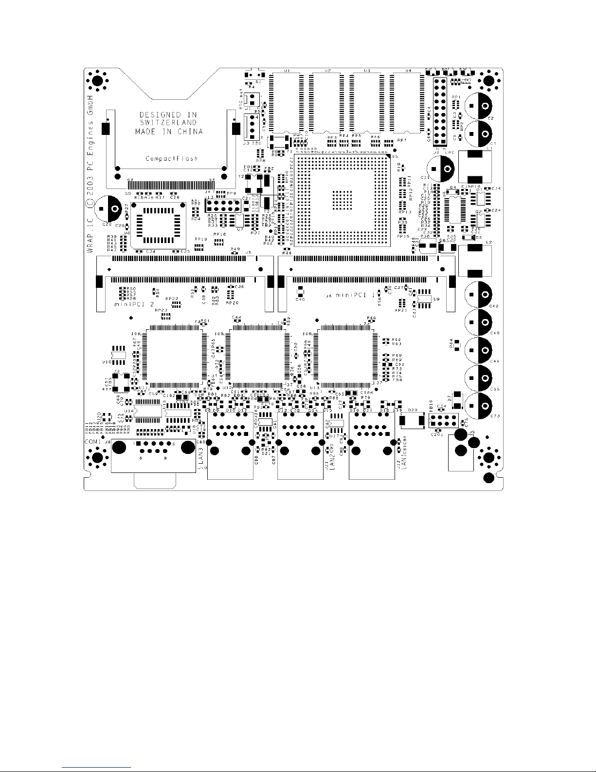
WRAP.1C mechanical dimensions 23
WRAP.2B connector pinouts 24
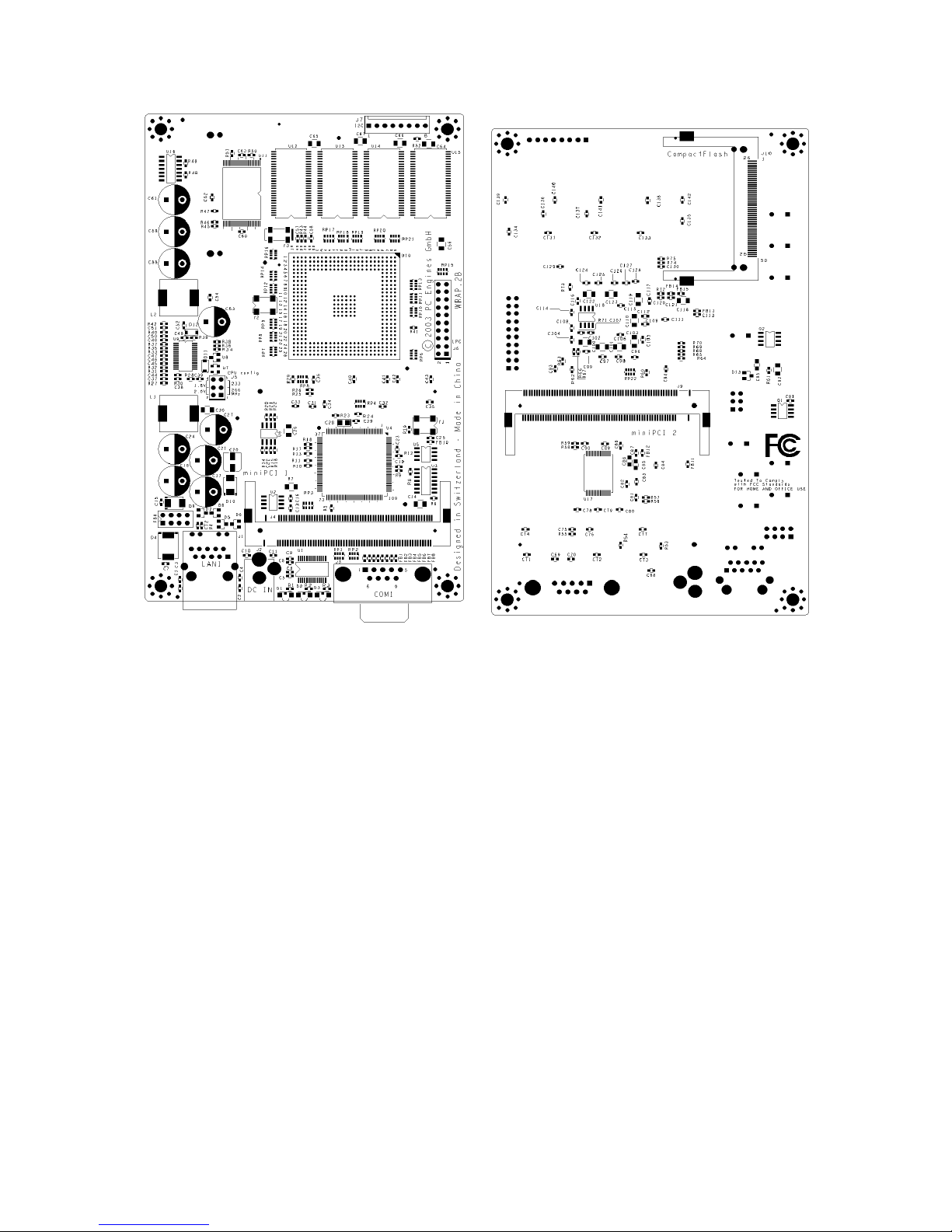
WRAP.2B mechanical dimensions 25
Resources 27

WRAP router platform 4 2/13/2007
Federal Communications Commission Statement
This device complies with Part 15 of the FCC Rules. Operation is subject to the following two
conditions: (1) this device may not cause harmful interference, and (2) this device must accept any
interference received, including interference that may cause undesired operation.
This equipment has been tested and found to comply with the limits for a Class B digital device,
pursuant to Part 15 of the FCC Rules. These limits are designed to provide reasonable protection
against harmful interference in a residential installation. This equipment generates, uses and can
radiate radio energy. If this equipment is not installed and used in accordance with the
manufacturer’s instructions, it may cause harmful interference to radio communications. However,
there is no guarantee that interference will not occur in a particular installation. If this equipment
does cause harmful interference to radio or television reception, which can be determined by
turning the equipment off and on, the user is encouraged to correct the interference by one or more
of the following measures:
• Reorient or relocate the receiving antenna.
• Increase the separation between the equipment and receiver.
• Connect the equipment to an outlet on a circuit different from that to which the receiver is
connected.
• Consult the dealer or an experienced radio/TV technician for help.
This board is designed for installation in a shielded enclosure (metal or plastic with conductive
coating). Shielded cables are required on LAN and serial ports to assure compliance with FCC
regulations.
A copy of the test report will be provided on request.
CE Declaration of Conformity
We, PC Engines GmbH, declare that WRAP.1C / WRAP.1D, when installed in the PC Engines
metal enclosure, is in conformance with:
- EN 61000-6-3 and EN 61000-6-4 (EMI emissions, residential and industrial)
- EN 61000-6-1 and EN 61000-6-2 (ESD, susceptibility, residential and industrial)
A copy of the test report will be provided on request.
Compliance information
For FCC, WRAP has been tested as a CPU board, installed in an enclosure, with the top cover
removed. No further testing should be required if the board is used with other FCC tested modular
components. Please see http://www.fcc.gov/oet/ for more details. The responsible party for FCC is
the importer.
Testing for CE mark must be done at the level of the complete product, possibly including the
wireless cards. Please contact PC Engines for assistance and documentation.
For satisfactory resistance to electrostatic discharge events (ESD), the WRAP board should be
grounded (e.g. through the mounting holes, or the serial port connector).

WRAP router platform 5 2/13/2007
Recycling / disposal
Do not discard electronic products in household trash !
All waste electronics equipment should be recycled properly. Actual procedures depend on your
country.
Information for the recycler:
PC Engines enclosures are made of Aluminum.
Batteries, if present, should be cut off or removed from the socket and recycled separately.
PCB boards may include SnPb (tin-lead) solder and should be recycled properly.

WRAP router platform 6 2/13/2007
Introduction / features
WRAP is a small single board computer optimized for wireless access and network routing
applications.
• National SC1100 CPU, 233 or 266 MHz 5x86 CPU, 16KB cache
• 2 or 3 Ethernet channels (National DP83816); 1 channel on WRAP.2B
• 2 or 1 miniPCI sockets for 802.11 wireless cards and other expansion
• 64 MB SDRAM, 64 bit wide for high memory bandwidth
• 128 KB flash for tinyBIOS system BIOS.
• CompactFlash header for user’s operating system and application
• 7 to 18V DC supply through DC jack or passive power over LAN 1 connector
• 1 serial port (DB9 male)
• Watchdog timer built into SC1100 CPU
• LM77 thermal monitor (not on WRAP.2D or WRAP.2E)
• Header for I2C bus (can be used for front panel interface)
• Header for LPC bus (can be used for I/O expansion)
• 3 LEDs and 1 pushbutton switch, freely programmable.
OEM options
The following accessories are available:
• CompactFlash cards
• Power over Ethernet injector POE.1A
The following options can be configured for larger orders:
• DRAM size (32 MB, 64 MB, 128 MB)
• 1 or 3 Ethernet channels (limit to 1 miniPCI if 3 Ethernet)
• 1 or 0 Serial ports
• Delete front panel LEDs and switch
• Custom BIOS adaptations as needed
• Full BIOS source can be licensed for adaptation by OEM
• USB port (no power over Ethernet, 5V DC supply only)
• Full custom board versions.
WRAP router platform 7 2/13/2007
WRAP router platform 8 2/13/2007
Technical data
Power supply +12V DC, ~ 0.25A halt, ~ 0.4A active (excluding miniPCI cards)
recommended range +7 to +18V DC, TVS limit at 20V !
Center pin = positive, sleeve = ground.
Temperature range 0 to 50°C. The temperature range may be extended by using a CPU heat sink
(not included), and reducing CPU frequency to 233 MHz.
Dimensions WRAP.1C = 6 x 6” (152.4 x 152.4 mm)
WRAP.2B = 3.937” x 6.3” (100 x 160 mm)
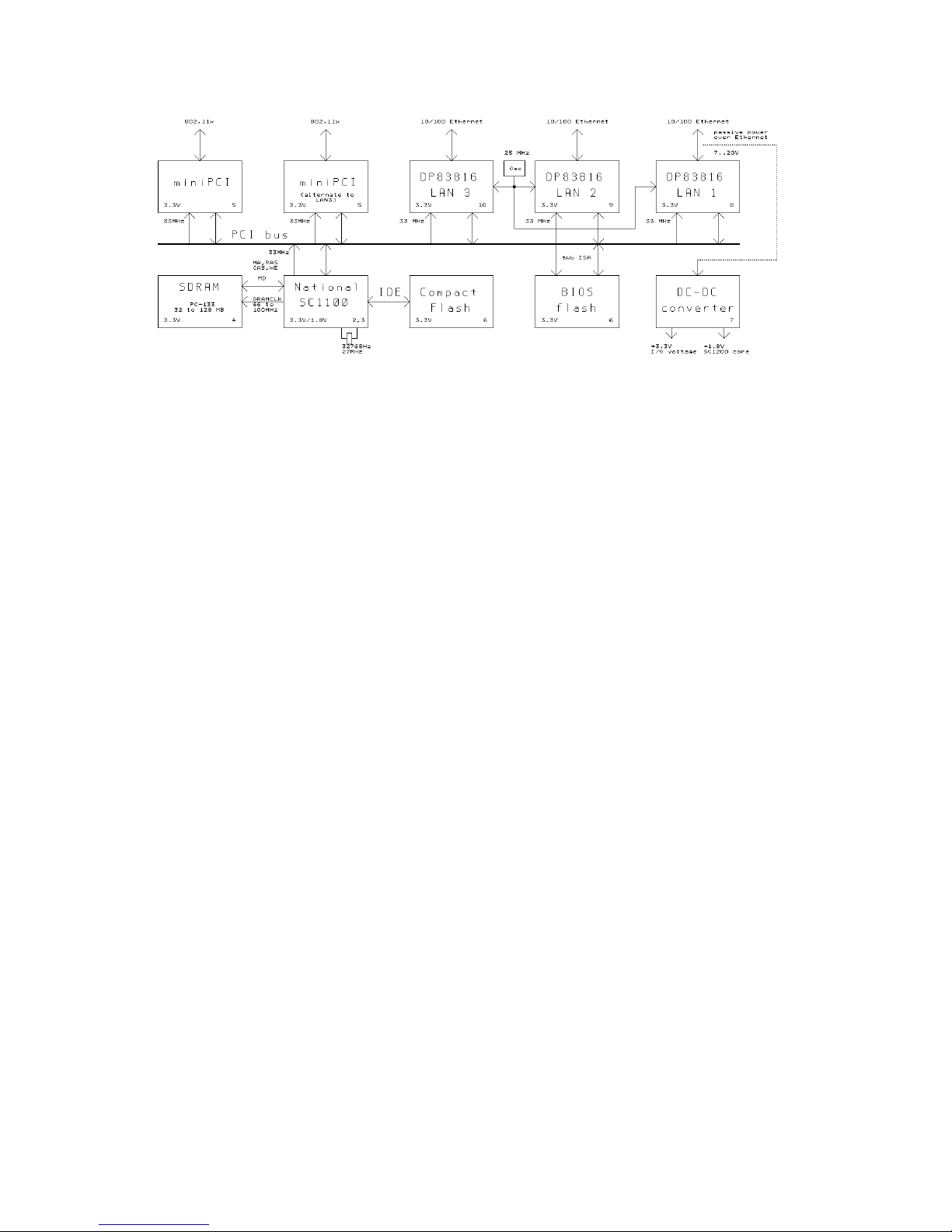
Block diagram
Full schematics are available on the PC Engines web site.
WRAP router platform 9 2/13/2007
Getting started…
- Connect a DC power supply to the DC jack J9. 2.1 mm center pin = positive, sleeve = ground.
Supply voltage should be between 7V and 18V (TVS on the input starts clamping around 20V).
Power supply should be able to supply at least 7.5W, 15W suggested for more margin and
reliability.
- Connect the serial console using a DB9 null modem cable. Default serial port parameters are
38400 8N1. Do NOT use a 1:1 connected serial cable, as the serial port may get damaged.
- While power is off, insert CompactFlash card with your operating system and application in
CompactFlash header J4. Hot swap of CompactFlash cards is not supported !
- Power on…
You should see tinyBIOS startup messages, memory size, CF disk geometry on the serial console.
Setup options
Configure your terminal emulator for 38400 8N1 (default baud rate), no handshake. To enter
setup, type S during the memory test. You should see somethink like the following:
PC Engines WRAP platform
tinyBIOS V1.4a (C)1997-2003 PC Engines
640 KB Base Memory
64512 KB Extended Memory
01F0 Master 848A HYPERSTONE FLASH DISK
Phys C/H/S 497/4/32 Log C/H/S 31/32/63
WRAP setup
(9) 9600 baud *3* 38400 baud
(C) CHS mode *L* LBA mode
(X) Xmodem upload (Q) Quit
 Loading...