

PC Electronics TX70-5s User Manual
P. C. Electronics 2522 Paxson Lane Arcadia CA 91007-8537 USA ©2013
Tel: 1-626-447-4565 m-th 8am-5:30pm pst (UTC - 8) Tom (W6ORG) & Mary Ann (WB6YSS)
Web site: http://www.hamtv.com Email: ATVinfo @ hamtv.com
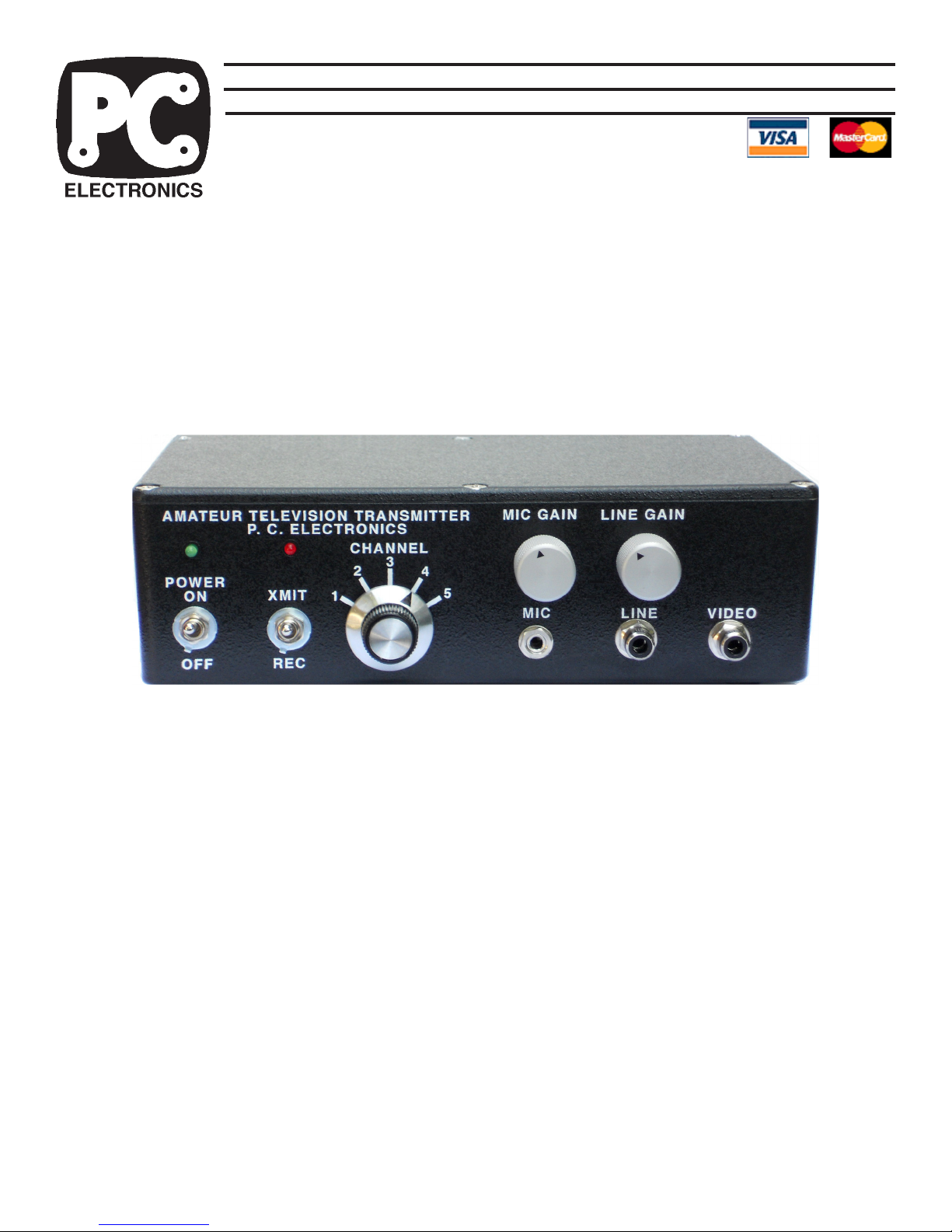
TX70-5s 70 CM ATV TRANSMITTER
USERS MANUAL
The TX70-5s transmitter is designed to provide >4Watts peak envelope power (sync tip) of video
modulated RF in the 70 CM (420-450 MHz) amateur band on any of 4 switch selected frequencies -
439.25, 434.0, 427.25 and 426.25 MHz - with a duty cycle of 15 minutes on and 5 off. Longer key down
periods can be done at reduced power or by blowing air on the enclosure.
Any licensed T echnician class or higher Radio Amateur may operate this transmitter in accordance
with 47 CFR part 97 of the FCC Rules and Regulations.
The TX70-5s accepts U.S.A. standard composite video (1 volt pk-pk) from any source such as
color or black and white cameras with video output or camcorders, VCR’s, or DVR’s for transmission.
Audio from these sources or a low impedance dynamic mic is also transmitted on the 4.5 MHz sound
subcarrier. T ransmit / receive power and antenna switching is provided for a companion high sensitivitty
TVC-4s downconverter. A cable ready TV may also be used to receive: 439.25 MHz equals cable
channel 60, 434 can be received on cable channel 59, and 427.25 or 426.25 received on cable channel
58.
PLEASE read through this manual before plugging in an cables and attempting operation. Each
connector and control is described here to enable your proper hookup and operation. Also the unique
video practices associated with ATV and the 70 CM band are described. More information on ATV can
be found on our Application Notes web page at www.hamtv.com.
1
TX70-5s ATV Transmitter Quick Start
Place the transmitter on a flat surface with no other objects within 2 inches. This is important for convection
cooling, especially the right side during key down periods greater than 5 minutes - the enclosure will become
warm to the touch. If key down periods will exceed 30 minutes or the ambient temperature is above 80 degrees,
air needs to be blown over the top and right side of the enclosure or turn the power down to 3Wpep (no video).
Connect the red lead from the DC power jack to a good regulated 12 to 14 Vdc >2A power supply or battery
directly and the black lead to negative or ground. Longer leads or junction boxes with other gear could put noise
in the picture.
Connect a good low VSWR 70cm Antenna using low loss 50 Ohm coax to the antenna jack. Best not to use
adaptors, but strictly N plugs with 420 MHz and above.to minimize losses. If you have a RF power meter that is
rated for 70cm, you can put it in the antenna coax line for the initial VSWR and system tests.
Select the local ATV frequency from the 4 (ch 1 not used) available on the front panel channel switch. Make
contact with a close by ATVer on the 2 meter coordination and talk back frequency to make sure the frequency or
repeater is clear and have some one to comment on your tests. Watching yourself on another TV in the shack
can give false results from overload or multipath.
Flip the Power switch to on and the green LED will light if you connected to the power supply correctly. Flip the
XMIT/REC switch to XMIT and the green will go off (as well as the downconverter if connected) and the red LED
and RF output will come on in 2-3 seconds. Verify less than 10% reflected power within 15 seconds before further
operation. We set the Peak envelope power for 4.2 Watts at the lowest power channel with no video. If all is OK,
you can plug in the camera video, line and or mic audio and optional video monitor. Set the Mic and/or Line Audio
gain as you speak normally at normal distance up to the point that the red LED winks off, then slightly back down.
When the XMIT switch is on, you are still transmitting when the red LED winks off during audio over deviation
peaks. Have the local ATVer talk your antenna rotation in for best picture via two meter voice.
Please read the detailed information on each connector and control that follows in this manual.
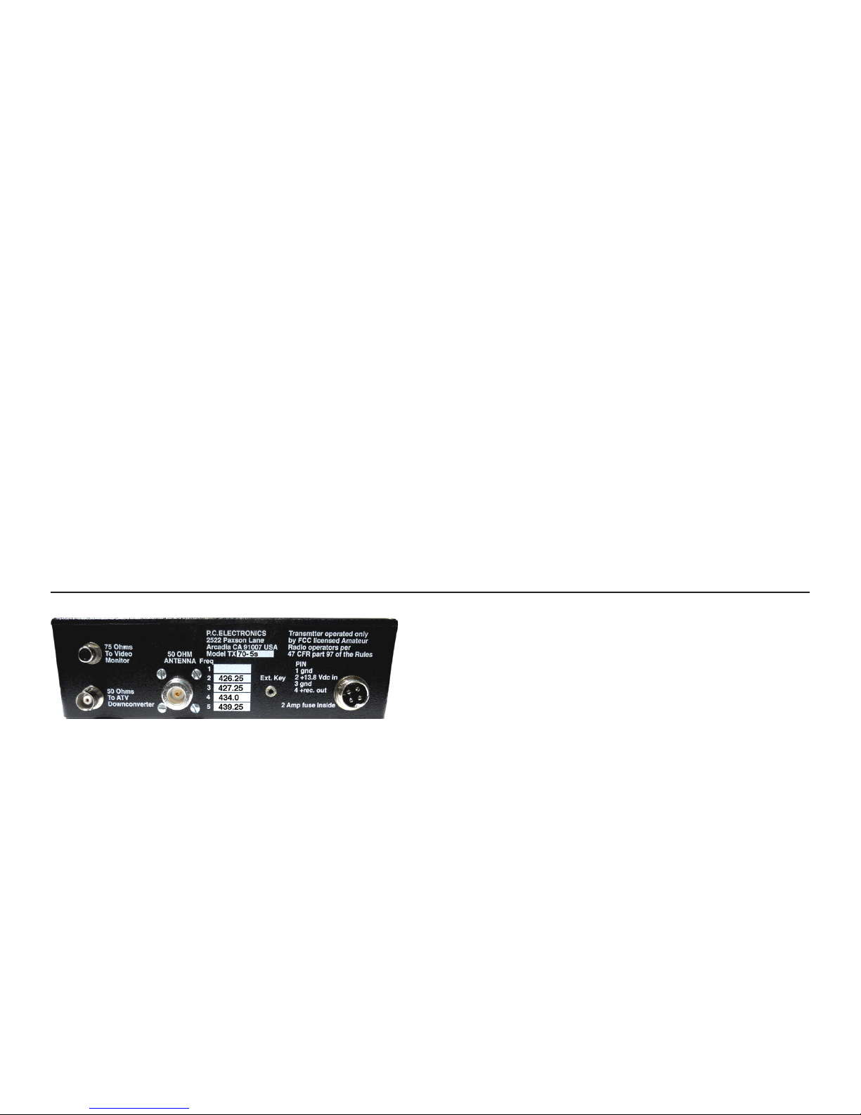
REAR PANEL:
POWER INPUT JACK. A 4 pin plug 2 ft cable is provided for
connection to your source of +12 to14 Vdc and to a
downconverter. Currant draw is <2A in transmit. Pin 1 is DC
ground and a black wire. Pin 2 is + and red. A cable with a
coaxial plug on the end connects to pins 3 (-) and 4 (+) to
output to a downconverter in receive. Power coaxial plug is
center +. The TX70-5s works best from a well regulated
voltage source with leads no longer than necessary. The
transmitter is set up by us from a regulated 13.8 Vdc supply .
Do not exceed 15 Vdc input. In case the voltage is reversed,
there is a internal series diode to prevent damage to the
unit. 16 v zeners on the sound and T/R relay boards should
blow the internal 2A fuse if this voltage is exceeded.
Any ripple or noise on the DC line may be seen in the
transmitted video. For this reason, if a single large power
supply is used to power this and other equipment, all leads
must connect directly at the power supply terminals, not to
an external terminal block. If an external amp is added, it is
best to run it from its own separate power supply.
DOWNCONVERTER POWER. A 2 ft cable is supplied with
a 2.1 X 5.5 mm plug on the end to connect from this jack to
a TVC downconverter . DC power (center is +) is at this jack
when the XMIT / REC switch is in REC and open when in
XMIT.
2 AMP FUSE INSIDE. The TX70-5s itself draws about 1.5
amp in transmit, and .1 amp plus external downconverter in
receive - A 2.0 amp 3AG fuse should handle both.
EXT KEY JACK. Grounding the tip keys the transmitter.
This jack is in parallel with the front panel transmit/receive
(XMIT/REC) toggle switch and can be used to key the
transmitter from an external switch to ground or key an
amplifier as long as the amp is run from a 13.8V power supply .
50 OHM 70 CM ANTENNA. A UG21 type N plug is provided
to attatch to low loss .5" size 50Ω coax. Losses at 70 CM
are very high in transmission lines. We suggest using the
foam filled types such as Belden 8214, or semi rigid Belden
9913 or Times LMR400. Put the connector together properly ,
or buy a ready made cable. The type N connector has good
moisture resistance and low loss at UHF but use two layers
of vinyl tape or Coax Seal on all outside connections to
prevent moisture contamination. The antenna and feed line
are the most important part of your A TV system, and therefore
the last item to just try and get by with.
2
 Loading...