

PC Electronics TX70-.1s User Manual
P. C. Electronics 2522 Paxson Lane Arcadia CA 91007-8537 USA ©2014
Tel: 1-626-447-4565 m-th 8am-5:30pm pst (UTC - 8) Tom (W6ORG) & Mary Ann (WB6YSS)
Web site: http://www.hamtv.com Email: ATVinfo @ hamtv.com
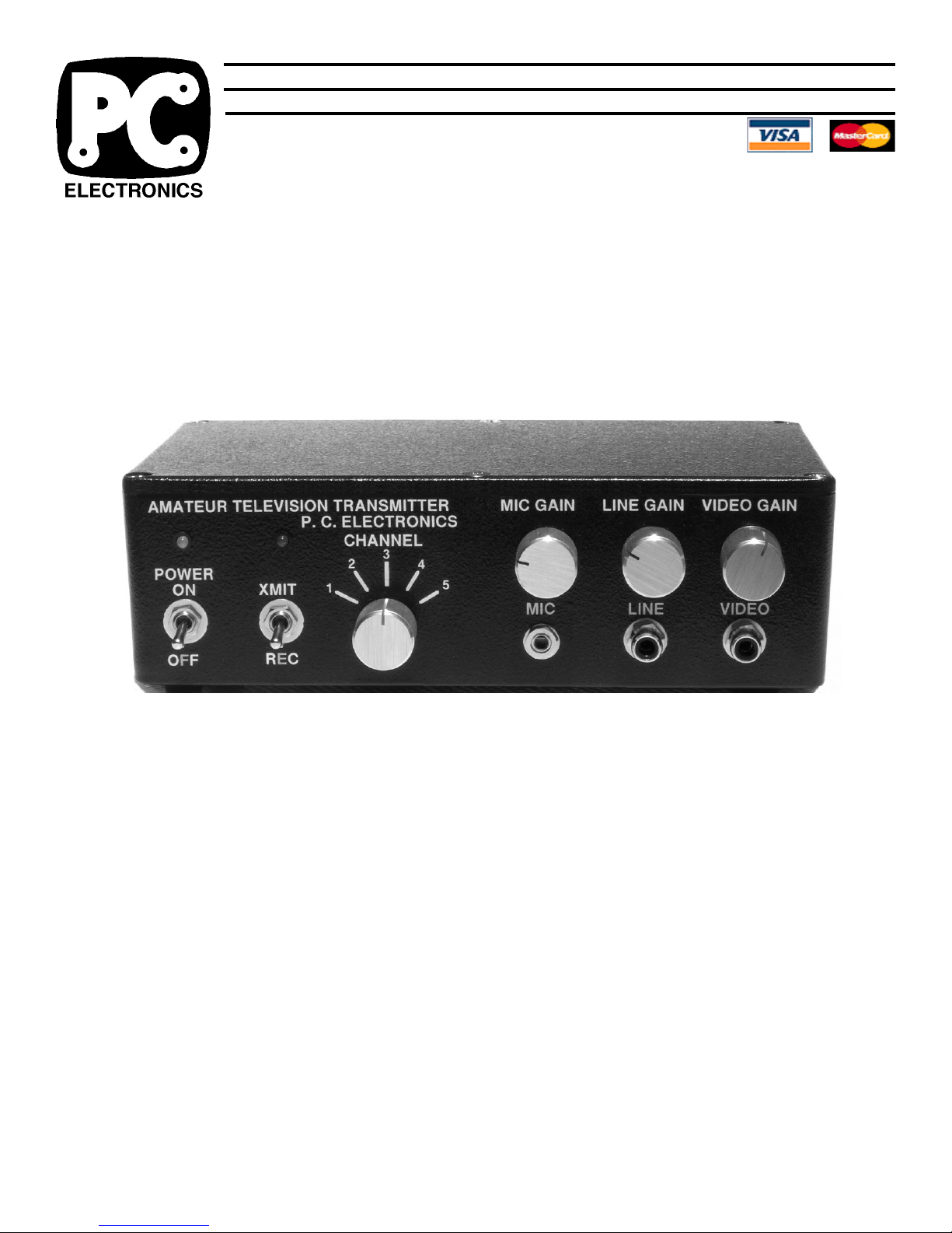
TX70-.1s 70 CM ATV TRANSMITTER
USERS MANUAL
The TX70-.1s transmitter is designed to provide 50 - 100 mW continuous duty peak envelope
power (sync tip) of video modulated RF in the 70 CM (420-450 MHz) amateur band on 4 switch selected
frequencies and to drive a linear amplifier. Any licensed Technician class or higher Radio Amateur may
operate this transmitter in accordance with 47 CFR part 97 of the FCC Rules and Regulations. The
TX70-.1s accepts U.S.A. standard composite video (1 volt pk-pk) from any source such as color or black
and white TV cameras or camcorders, VCRs, or computers for transmission. Audio from these sources
or a low impedance dynamic mic is also transmitted on the 4.5 MHz sound subcarrier. Transmit / receive
power and antenna switching is provided for the companion TVC-4s downconverter.
PLEASE read through this manual before plugging in an cables and attempting operation. Each
connector and control is described here to enable your proper hookup and operation. Also the unique
video practices associated with ATV and the 70 CM band are described.
1
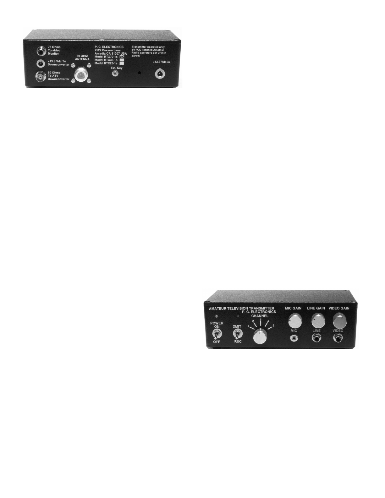
REAR PANEL:
POWER INPUT JACK. A 2.1 x 5.5mm plug cable is provided
for connection to your source of +12 to14 Vdc. Currant draw
is <500 MA in transmit. Center of the plug and the marked
side of the cable is +, all black is - or ground. If used at a
repeater site, make a cable using RG174 coax. The TX70.1s works best from a well regulated voltage source with leads
no longer than necessary. The transmitter is set up by us
from a regulated 13.8 Vdc supply. Do not exceed 15 Vdc
input. There is a series diode incase the voltage is reversed
and a 16 v zener on the sound board which should blow the
1A fuse if this voltage is exceeded
Any ripple or noise on the DC line may be seen in the
transmitted video. For this reason, if a single large power
supply is used to power this and other equipment, all leads
must connect directly at the power supply terminals, not to
an external terminal block. If a external amp is added, it is
best to run it from its own separate power supply . The Radio
Shack 22-120 regulated power supply will run both the TX70.1s and TVC-4G.
DOWNCONVERTER POWER JACK. A 6 FT cable is
supplied with 2.1 X 5.5 mm plugs on each end to connect
from this jack to a TVC downconverter. + power is at this
jack when the XMIT / REC switch is in REC and open when
in XMIT.
1 AMP FUSE INSIDE. The TX70-.1s itself draws about .5
amp in transmit, and .1 amp plus external downconverter in
receive - a 1.0 amp 3AG fuse should handle both.
50 OHM 70 CM ANTENNA. A UG21 type N plug is provided
to attatch to low loss .5" size 50Ω coax. Losses at 70 CM
are very high in transmission lines. We suggest using the
foam filled types such as Belden 8214, or semi rigid Belden
9913 or Times LMR400. Put the connector together properly .
See ARRL HandBook ATV section. The type N connector
has good moisture resistance and low loss at UHF but use
two layers of vinyl tape or coax seal on all outside connections
to prevent moisture contamination. The antenna and feed
line are the most important part of your ATV system, and
therefore the last item to just try and get by with.
Take great care with preparing connectors and cable. If
using an external amp, on initial turn on, do not transmit more
than 10 seconds if the reflected power is more than 10% or
2:1 VSWR. You could damage the final or modulator
transistor. Also, VSWR or being too near your antenna can
cause RF interference in your camera or buzz in the audio.
Use a good resonant broad bandwidth 70 CM antenna
such as the 15 element Quagi described in the ARRL
HandBook Chapter 33 or commercially made antennas like
the DSFO25-A TV, OAL 5L-70cm or circularly polarized OAL
7CP-70cm. Do not be tempted to just try it out with a rubber
duckie, 2 meter antenna, or other antenna not specifically
designed for the video carrier frequency . Place the antenna
as high as practical, at least above the trees or roof tops.
See the section on dx vs. power vs. gain on page 4.
EXT KEY JACK. Grounding the tip keys the transmitter.
This jack is in parallel with the front panel transmit/receive
toggle switch and can be used to key the transmitter from a
repeater controller or to provide a grounding key to an external
amplifier as long as the amp is run from a 13.8V power supply .
FRONT PANEL:
75 OHMS TO MONITOR. This output provides the composite
video from the front panel Video jack during receive to enable
you aim the camera and to best adjust the focus and lighting,
etc. Use a RCA plug shielded cable to connect to your video
monitor or VCR video in.
In this model, there is no video present a this jack when
in transmit.
50 OHMS TO ATV DOWNCONVERTER. This BNC output
jack is connected to the antenna input of your 70 CM 420450 MHz ATV down-converter. Downconverters for other
bands are not connected to the TX70-.1s, rather to their own
antenna and left on when transmitting on 70cm for full duplex
or crossband repeat. If a TVC-4s downconverter is used
you will need a short 50 Ohm cable with a male BNC on one
end and type N on the other. This can be made up with
Radio Shack RG58/U (276-1326) plus UG88 (278-103) and
N (278-151) connectors or equivalent. Keep this lead short
to minimize losses in receive. The TX70-.1s contains a T/R
relay to switch the antenna input as well as DC power
between the downconverter and the transmitter.
VIDEO INPUT. This input accepts any standard NTSC
composite video into 75Ω from cameras, VCRs, computers,
SSTV or RTTY converters, home satellite converters, etc.
Use RCA phono plug and shielded cable (Radio Shack 15-
1535) up to 12' or RG59 for longer runs. When unplugging,
only twist clockwise to keep the jack from coming loose.
VIDEO GAIN control. This sets the white level or depth of
modulation of the selected video source. In transmit, the
knob should be slowly increased clockwise just to the point
of white smearing or blooming as described back to you from
a station located at least a quarter mile away. The distant
A TV receiving station can describe your picture back to you
over 2 meters.
2
 Loading...