

Page 1
P. C. Electronics 2522 Paxson Lane Arcadia CA 91007-8537 USA ©2011
Tel: 1-626-447-4565 m-th 8am-5:30pm pst (UTC - 8) Tom (W6ORG) & Mary Ann (WB6YSS)
Web site: http://www.hamtv.com Email: ATVinfo @ hamtv.com
TX33-.1s 70 CM ATV TRANSMITTER
USERS MANUAL
The TX33-.1s transmitter is designed to provide 50-100 milliwatts peak envelope power (sync tip)
of video modulated RF in the 33 CM (902-928 MHz) amateur band on any of 5 switch selected frequencies
- 910.25, 91 1.25, 913.25, 919.25 and 923.25 MHz. For higher power, a Downeast Miicrowave 3340PA
linear amplifier can be added.
Any licensed T echnician class or higher Radio Amateur may operate this transmitter in accordance
with 47 CFR part 97 of the FCC Rules and Regulations.
The TX33-.1s accepts U.S.A. standard composite video (1 volt pk-pk) from any source such as
color or black and white cameras with video output or camcorders, VCR’s, or DVR’s for transmission.
Audio from these sources or a low impedance dynamic mic is also transmitted on the 4.5 MHz sound
subcarrier. T ransmit / receive power and antenna switching is provided for a companion high sensitivitty
TVC-9s downconverter connected to a TV on channel 3 may be used to receive:
PLEASE read through this manual before plugging in an cables and attempting operation. Each
connector and control is described here to enable your proper hookup and operation. Also the unique
video practices associated with ATV and the 33 CM band are described. More information on ATV can
be found on our Application Notes web page at www.hamtv.com.
1
Page 2
TX33-.1s ATV Transmitter Quick Start
Place the transmitter on a flat surface with no other objects within 2 inches. This is important for convection
cooling and running for periods of more than 10 minutes continuous key down.
Connect the red lead from the DC power jack to a good regulated 12 to 14 Vdc >1A power supply or battery
directly and the black lead to negative or ground. Longer leads or junction boxes with other gear could put noise
in the picture.
Connect a good low VSWR 33cm Antenna using low loss 50 Ohm coax to the antenna jack. Best not to use
adaptors, but strictly N plugs with 420 MHz and above.to minimize losses. If you have a RF power meter that is
rated for 33cm, you can put it in the antenna coax line for the initial VSWR and system tests.
Select the local ATV frequency from the 5 available on the front panel channel switch. Make contact with a close
by ATVer on the 2 meter coordination and talk back frequency to make sure the frequency or repeater is clear and
have some one to comment on your tests. Watching yourself on another TV in the shack can give false results
from overload or multipath.
Flip the Power switch to on and the green LED will light if you connected to the power supply correctly. Flip the
XMIT/REC switch to XMIT and the green will go off (as well as the downconverter if connected) and the red LED
and RF output will come on in 2-3 seconds. If driving an amplifier, verify that there is less than 10% reflected
power within 15 seconds before further operation. If all is OK, do the linear amplifier ATV set up procedure. after
that, you can plug in the camera video, line and or mic audio. Set the Mic and/or Line Audio gain as you speak
normally at normal distance up to the point that the red LED winks off, then slightly back down. When the XMIT
switch is on, you are still transmitting when the red LED winks off during audio over deviation peaks. Have the
local ATVer talk your antenna rotation in for best picture via two meter voice.
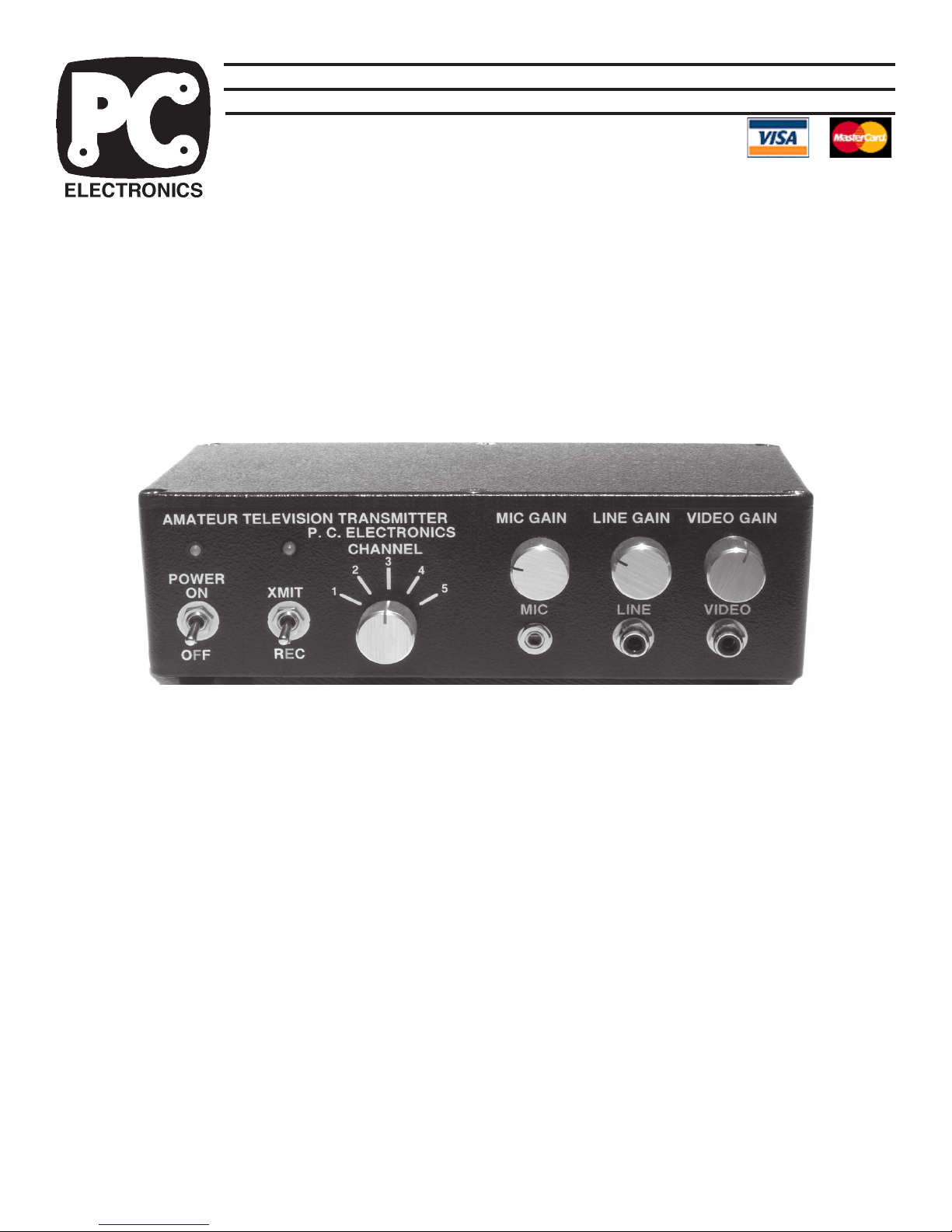
Please read the detailed information on each connector and control that follows in this manual.
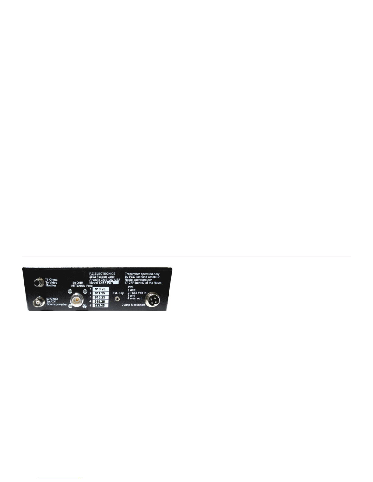
REAR PANEL:
POWER INPUT JACK. A 4 pin plug 2 ft cable is provided for
connection to your source of +12 to14 Vdc and to a
downconverter. Currant draw is <2A in transmit. Pin 1 is DC
ground and a black wire. Pin 2 is + and red. A cable with a
coaxial plug on the end connects to pins 3 (-) and 4 (+) to
output to a downconverter in receive. Power coaxial plug is
center +. The TX33-.1s works best from a well regulated
voltage source with leads no longer than necessary. The
transmitter is set up by us from a regulated 13.8 Vdc supply .
Do not exceed 15 Vdc input. In case the voltage is reversed,
there is a internal series diode to prevent damage to the
unit. 16 v zeners on the sound and T/R relay boards should
blow the internal 1A fuse if this voltage is exceeded.
Any ripple or noise on the DC line may be seen in the
transmitted video. For this reason, if a single large power
supply is used to power this and other equipment, all leads
must connect directly at the power supply terminals, not to
an external terminal block. If an external amp is added, it is
best to run it from its own separate power supply.
DOWNCONVERTER POWER. A 2 ft cable is supplied with
a 2.1 X 5.5 mm plug on the end to connect from this jack to
a TVC downconverter . DC power (center is +) is at this jack
when the XMIT / REC switch is in REC and open when in
XMIT.
2 AMP FUSE INSIDE. The TX33-.1s itself draws less than.5
amp in transmit, and .1 amp plus external downconverter in
receive - A 1.0 amp 3AG fuse should handle both.
EXT KEY JACK. Grounding the tip keys the transmitter.
This jack is in parallel with the front panel transmit/receive
(XMIT/REC) toggle switch and can be used to key the
transmitter from an external switch to ground or key an
amplifier as long as the amp is run from a 13.8V power supply .
50 OHM 33 CM ANTENNA. A UG21 type N plug is provided
to attatch to low loss .5" size 50Ω coax. Losses at 33 CM
are very high in transmission lines. We suggest using the
foam filled types such as Belden 8214, or semi rigid Belden
9913 or Times LMR400. Put the connector together properly ,
or buy a ready made cable. The type N connector has good
moisture resistance and low loss at UHF but use two layers
of vinyl tape or Coax Seal on all outside connections to
prevent moisture contamination. The antenna and feed line
are the most important part of your A TV system, and therefore
the last item to just try and get by with.
2
Page 3
If you are driving an amp, video plugged in and have a
peak reading RF power meter, you will be reading the peak
sync level and pep. With video plugged in and using an
average reading meter, it will read less, and down to half
with an all white picture, but sync tip power will still be the
same as measured with a peak reading meter. This is the
nature of cable analog NTSC or AM video transmission,
similar to SSB voice peak and average RF power
measurements with complex analog modulation.
On initial turn on, do not transmit more than 15 seconds
if the reflected power is more than 10% or 2:1 VSWR. You
could damage the final power FET. Also, VSWR or being
too near your antenna can cause RF interference in your
camera or buzz in the audio.
Use a good resonant broad bandwidth 33 CM antenna
like the Directive Systems 3318LYRM, circularly polarized
OAL 33/23 Helix, or homebrew antennas shown on our app
note web page. Do not be tempted to just try it out with a
rubber duckie, 2 meter antenna, or other antenna not
specifically designed for the video carrier frequency. Place
the antenna as high as practical, at least above the trees or
roof tops.
75 OHMS TO MONITOR. This output provides the composite
video from the front panel Video jack during receive to enable
you to aim the camera and to best adjust the focus and
lighting, etc. before transmitting. In transmit, there is no
output. Use a RCA plug 75 Ohm shielded cable to connect
to your video monitor or VCR video in.
50 OHMS TO ATV DOWNCONVERTER. This BNC output
jack is connected to the antenna input of your 33 CM 902928 MHz ATV downconverter. Downconverters for other
bands are not connected to the TX33-.1s, but rather to their
own antenna and left on when transmitting on 33cm for full
duplex or crossband repeat. If a TVC-9s downconverter is
used, a short 50 Ohm cable with a male BNC on one end
and type N adaptor on the other is supplied. The TX33-.1s
contains a T/R relay to switch the antenna input as well as
DC power between the downconverter and the transmitter.
VIDEO INPUT . This input accepts any standard NTSC 1Vpp composite video into 75Ω from cameras, VCRs, computers,
SSTV or RTTY converters, home satellite converters, etc.
Use RCA phono plug and shielded cable (Radio Shack 15-
1535) up to 12' or RG59 or RG-6 for longer runs. When
unplugging, only twist clockwise to keep the jack from working
lose over time.
LINE AUDIO INPUT . High level line audio usually from the
same source as plugged into the companion Video input is
plugged into this jack using another RCA phono plug shielded
cable. Minimum level is .1 v pk-pk into a 10K load.
LINE AUDIO GAIN control varies the high level audio applied
to the subcarrier from the front panel audio input RCA phono
jack. Increase the level to the point where the red XMIT light
winks off, and then back down the gain slightly . This audio is
independent and mixed with the mic audio. This makes
varying the level of a video tape audio verses mic for voice
over comments easy. Peak deviation is set by an internal
pot on the FMA5-G sound subcarrier board.
MIC jack accepts any low Z dynamic mic in the range of 100
- 600 Ohms with a mini plug. Mic audio is active at all times
and mixes with the camera or VCR line audio input to give
more direct pickup, commenting while running video tapes,
etc. Mikes must have a shielded cable to prevent RF pickup
hum and buzz. Unidirectional mics are suggested for full
duplex to minimize speaker feedback or to reduce pickup of
unwanted sounds and noise from the sides. Electret and
amplified mics are very susceptible to RF pickup - buzz and
should not be used.
MIC GAIN control varies the level of the low Z dynamic mic.
It is independent of the line audio level. Speak directly into
the microphone at the normal operating distance. Increase
the level to the point where the red XMIT light winks off, and
then back down the gain slightly. There is a volume
compressor that will keep the audio at the standard 25 kHz
deviation and 40 kHz peaks. Audio usually drops out about
the same time as color does in a snowy picture - P3 depending on the TV sets audio IF gain and limiting.
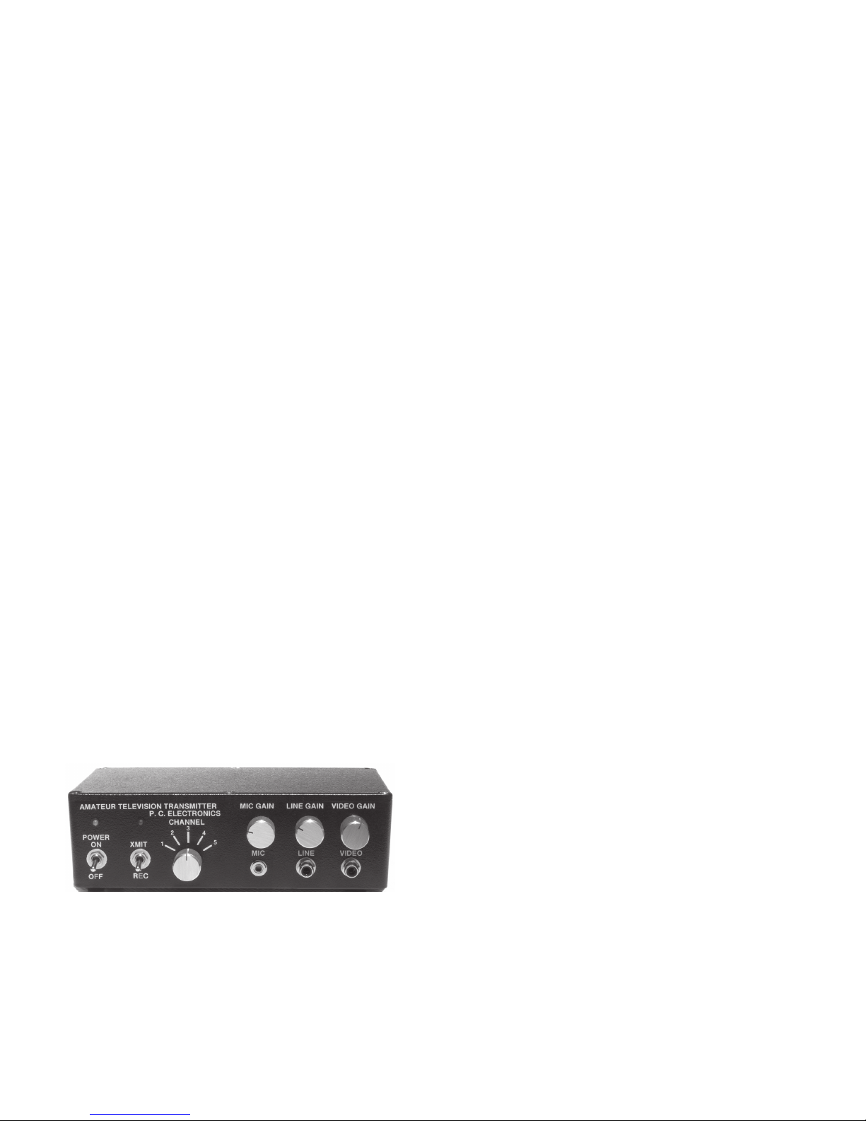
FRONT PANEL:
VIDEO GAIN control. This sets the white level or depth of
modulation of the selected video source. In transmit, the
knob should be slowly increased clockwise just to the point
of white smearing or blooming as described back to you from
a station located at least a quarter mile away. The distant
A TV receiving station can describe your picture back to you
over 2 meters.
CHANNEL SWITCH. This model has 5 synthesized
channels and are the same as our TVC-9s downconv .:
1 - 910.25 MHz
2 - 911.25 MHz
3 - 913.25 MHz
4 - 919.00 MHz
5 - 923.25 MHz
XMIT/REC switch. It is in parallel with the EXT KEY jack.
The red lamp above this switch will light whenever you are in
the transmit mode and the audio inputs are making <40 kHz
peak deviation. There is a delay of 2 to 3 seconds for this
LED to light and the RF output to come up. In receive, the
applied + voltage appears on the downconverter power jack
to power a TVC-9s 33CM ATV downconverter.
POWER ON switch turns on the applied +12 to 14 Vdc to the
TX33-.1s. If the green light does not come on, check the
fuse, polarity and determine why it blew before replacement.
3
Page 4
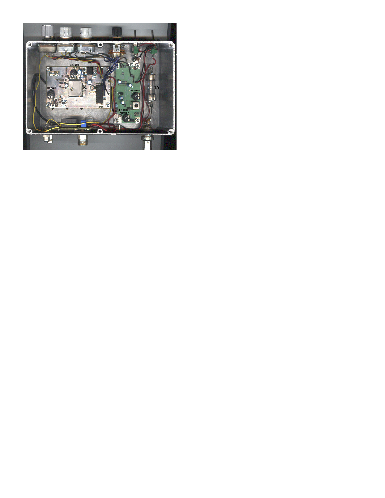
INTERNAL:
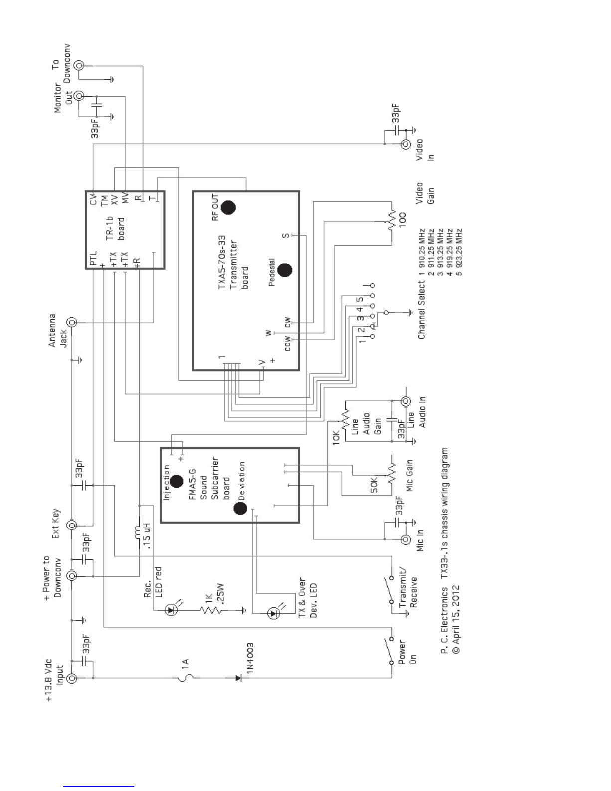
Also reference the wiring diagram on page 6.
AUDIO DEVIATION. Peak deviation is controlled by a pot
on the FMA5-G board for no more than 40kHz or 25 kHz
average. If you don’t have a communication monitor tuned
to 4.5 MHz above the video carrier, you can come close by
comparing the sound level with a cable broadcast channel.
EXTERNAL LINEAR AMPLIFIER SET UP. There are
specific model amplifier application notes on our web site
and why some work on ATV and others do not. Basically,
they all setup in the same way.
1. With no video source plugged in, turn the RF power pot
on the TXA5 board to its minimum power position (CCW).
Turn the Pedestal pot to full CCW . No video pluged in. Make
sure the amp is rated to be linear class A, AB or B and is
connected to a good 50 Ohm dummy load or low vswr
antenna (less than 10% reflected).
2. Turn on the amp and transmitter. Slowly increase the
TXA5 board RF output to no more than 90% of the amplifiers
rated power output level. For instance if the amp is rated at
40 Watts, set the RF output for 36 Watts. This will be the
sync tip or peak envelope power. Then set the Pedestal pot
for 55% to 60% of this pep. In our example this would be
between 36 X .6 = 21.6 Watts and 36 X .55 = 19.8 Watts.
3. Plug the camera back in and have a distant station on two
meters talk back to check your picture to make sure you
have done the pedestal and sync tip set up correctly . There
should be no instability or rolling from sync compression. An
average reading RF power meter will read the pedestal power
when no video is plugged in. With video in, the avearage
reading meter will show less power even though the sync tip
and pedestal power will be constant. An all white picture will
show a little less than half pep.
OPERA TING NOTES: A TV practices are somewhat dif ferent
from the other bands and modes. Another ham near you to
look for your video transmission will need to connect a 33cm
downconverter to a TV set on channel 3 and have a roof top
33cm antenna of the same polarity . Best if they talk back to
you on 2 meters. See our ATV Application Notes web page
for info on making a 33cm ground plane or simple beams if
they do not have one. Many ATV contacts are initiated by
calling or listening on an area 2 meter FM simplex ATV
coordination frequency (146.43 in 434.0 areas, and 144.34
in 439.25 transmit video areas due to the 3rd harmonic
relationship). Since we must use directional antennas to
make up for the 26 dB higher noise floor difference compared
to NBFM due to bandwidth (15 kHz vs. 3 MHz), the probability
of someone pointing their beam at you while at the same
time you at them and calling CQ is very low.
T wo meters, even for FM, has about 12 dB less path loss
than 33CM so that all possible ATVers can be received on 2
meter FM using just an omni antenna. You will find with
experience the correlation between 2 meter simplex and
33CM ATV. It is much easier for all local ATVers to monitor a
squelched 2 meter FM simplex channel than to try tuning
and swinging the 33CM beam looking for sync bars. Once
another A TV er comes up on 2 meters, you can roughly swing
the beams on each other before turning on the ATV
transmitter. Then, if the picture is better than 20% snow , the
video transmitting station can talk on the sound subcarrier,
and all those receiving him can talk back at the same time
on 2 meters (full duplex) to comment on picture content, etc.
Others listening to the 2 meter channel are often hooked
into ATV this way. You can also run full duplex audio and
video with another station on the 420 or 1200 MHz bands.
It is more fun as time goes on to have many hams put
their families, other hobbies, and varied interests on the
screen. Let others know your 2 meter A TV freq. by publishing
in local radio clubs newsletters, contact your local ARRL SCM,
or pick a night and time to start an ATV net. The TX33-.1s is
portable enough to give a little demo at your local radio club
or hamfest.
IF YOU BELIEVE THE TX33-.1s ISN’T WORKING, check
all cables and connections, internal fuse and 16V protection
zener, VSWR, power supply and DC voltages at the boards.
Then call or email us and describe the problem or ask any
questions you might have. It will save us both time and money
if we suggest some things to try that may have been overlooked, or for us to better evaluate the problem. The TX33.1s can be repaired by us for $80 plus parts cost in a few
days if we believe the problem is customer caused or nothing
wrong. If we determine that it was due to our workmanship
and materials within a reasonable time and given
circumstances then your cost is only the shipping to us.
However the repair and service policy stated in our latest
catalog will supercede the general policy listed here. Include
with the unit a filled out
from our web site. Normal turn around is 2 days after we
receive it. There is no other warranty expressed or implied.
We believe this policy is more realistic than the usual 90 day
warranty other amateur manufacturers have since various
parts have different expected lifetimes.
Return Authorization Form
- download
4
Page 5
5
 Loading...