


P. C. Electronics 2522 Paxson Lane Arcadia CA 91007-8537 USA ©2001
Tel: 1-626-447-4565 m-th 8am-5:30pm pst (UTC - 8) Tom (W6ORG) & Mary Ann (WB6YSS) O’Hara
24 hr FAX order line 1-626-447-0489 Email: tomsmb@aol.com
Web site: http://www.hamtv.com
TC70-20 70 cm ATV TRANSCEIVER
USERS MANUAL
The TC70-20 transceiver is designed to provide over 20 Watt p.e.p. (sync tip), continuous duty, of
AM video modulated RF in the 70 cm (420-450 MHz) Amateur band in transmit, and downconvert the
whole band to TV channel 2, 3 or 4 to enable receiving on any standard NTSC television set. Any
licensed code free Technician class or higher Radio Amateur may operate this transmitter in accordance
with 47 CFR part 97 of the FCC Rules and Regulations. The TC70-20 accepts U.S.A. standard composite video (1 volt pk-pk) from any source such as color or black and white TV cameras or camcorders,
VCRs, or computers for transmission. Audio from these sources or a low impedance dynamic mic is
also transmitted on the 4.5 MHz FM sound subcarrier.
PLEASE read through this manual before plugging in any cables and attempting operation. Each
connector and control is described here to enable your proper hookup and operation. Also the unique
video practices associated with ATV and the 70 cm band are described.
1 ©2001

REAR PANEL:
Keep 3”
minimum
clearance
around the
heat sink
and top of
box for
convection
cooling or
add a fan.
POWER INPUT JACK. A 4 pin plug and 3 ft long #18 cable
is provided for connection to your source of 12 to 14 Vdc.
Pin 1 is ground (black) and pin 2 (red) is +. The TC70-20
works best connected directly to the terminals of a well
regulated power supply with leads no longer than necessary .
The transmitter is set up by us with a regulated 13.8 Vdc
supply, if the voltage is <13.3 Vdc see amplifier / pedestal
set up on page 5. Do not exceed 15 Vdc input. There is a
16 v zener which should blow the fuse if this voltage is
exceeded or the supply leads get cross connected, but
semiconductors have been known to protect fuses. Any ripple
or noise on the DC line may be seen in the transmitted video.
Y ou will need a 13.8 Vdc regulated power supply capable of
4 Amps continuous. There is a 5 Amp fuse inside the unit.
TV. The downconverter output is at this jack during receive
for connection to your TV receiver antenna input. Run a 75
Ohm RG6 coax with F connectors. Radio Shack has cables
made up in various lengths (15-1530). If your TV does not
have a 75 Ohm coax input, use a balun at the TV (15-1 140).
Tune the TV to channel 2, 3 or 4 depending on which ever is
weakest or not on the air in your area. With the TC70-20 still
off, fine tune the TV set, with the AFC off, for all snow and no
adjacent channel feedthru. Now turn on the TC70-20 and
slowly tune the REC TUNE knob for the best picture from a
known close by ATV station. It is set up for 434 MHz to be at
channel 3 with the knob between 3 and 5 on the dial. Once
you have a picture, rotate your antenna for least snow or
strongest picture. Then ask the ATV transmitting station to
swing his antenna for the strongest picture. It’s best to
coordinate the tuning and antenna rotation on 2 meter FM.
The most popular ATV coordination frequencies are 144.34
and 146.430 MHz simplex. Select the one that does not
have a 3rd harmonic within the video passband on 70 cm.
The video transmitting station then talks to you on the sound
subcarrier, and the receiving stations talk back at the same
time (full duplex) on 2 meters.
indications due to overload and reflections. Even receiving
the 2nd harmonic 40 or more dB down around channel 80,
or on cable channels between 57 and 60 can give an
erroneous indication of transmitted picture quality . Only the
monitor output will be accurate, except when reset to drive
an external power amplifier.
50 OHM 70 CM ANTENNA. A UG21 type N plug is provided
to attatch to low loss .5" size 50Ω coax. Losses at 70 cm are
very high in transmission lines. We suggest using the foam
filled types (3.5 dB/100') such as Belden 8214, or semi rigid
(2.5 dB/100') Belden 9913. Take great care to put the N
plug together properly - see last page. The type N connector
has good moisture resistance and low loss at UHF but use
two layers of vinyl tape or coax seal on all outside connections
to prevent moisture contamination. The antenna and feed
line are the most important part of your ATV system, and
therefore the last item to just try and get by with.
Check out your antenna system with a RF power meter.
On initial turn on, do not transmit more than 10 seconds if
the reflected power is more than 10% (2.0 W max) or 2:1
VSWR. You could blow the M57716 power module. Also,
VSWR or being too near your antenna can cause RF pickup
interference in your camera or buzz in the audio. With no
video connected, the RF power meter should read between
11 to 15 Watts blanking pedestal power. Sync tip, p.e.p.,
equals 1.68 times the blanking power.
Use a good resonant broad bandwidth 70 cm antenna
such as the High-performance 432-Mhz Yagi’s described in
the 1995-2000 ARRL Handbook Chapter 20 or commercially
made antennas like the Old Antenna Lab 5L-70cm, DSFOATV-25, or circularly polarized KLM 435-18C & 435-40CX,
or Diamond F718L and NR-770H omnis. Do not be tempted
to just try it out with a rubber duckie, 2 meter antenna,
broadcast UHF TV or other antenna not specifically designed
for the video carrier frequency or 50 ohms. Place the antenna
as high as practical, at least above the trees or roof tops.
See the section on DX vs. Power vs. Gain on page 4.
FRONT PANEL:
TRANSMIT VIDEO MONITOR OUTPUT. This provides
composite video of your demodulated RF directly from the
antenna output during transmission periods to enable you to
best adjust the video gain, set focus and lighting, etc., rather
than a distant station describing these back to you on 2
meters. In receive it outputs the phono jack video input to
enable your setting up the picture on the monitor as you
receive another station on the TV. Use a RCA plug shielded
cable to connect to your video monitor or VCR video in. If
your TV receiver does not have a video input, the Radio
Shack 15-1273 RF Modulator can take the composite video
and modulate it up to channel 3 or 4 to make another TV set
into a monitor. Attempting to see your own video over the air
with a TV set at the same QTH most often gives false
TX FREQ. Transmit crystal frequency switch select.
VIDEO INPUT. This input accepts any standard NTSC
composite video into 75Ω from cameras, VCRs, computers,
SSTV or RTTY converters, home satellite converters, etc.
Use RCA phono plug shielded cable (Radio Shack 15-1535).
Push RCA phono plugs straight in, but pull and twist of f only
in the clock wise direction to keep jacks tight.
AUDIO INPUT. High level line audio usually from the same
source as plugged into the companion Video input is plugged
into this jack using another RCA phono plug shielded cable.
Minimum level is .1 v pk-pk into a 10K load. The level is
controlled by the line audio gain knob.
2

VIDEO GAIN control. This sets the white level or depth of
modulation of the selected video source. The knob should
be slowly increased clockwise just to the point of white
smearing or blooming as seen on an external video monitor,
and then backed down a little. The viewfinder in a color
camera can also be used if it can accept external video into
it, as some do for VCR playback. If you do not have any kind
of monitor, you might try having a distant A TV receiving station
describe your picture back to you over 2 meters. See monitor
output paragraph.
LINE AUDIO GAIN control. Nominal input is .1 to 1 Vp-p.
This control is independant of the mic audio gain. The mic
and line audio is mixed in the subcarrier generator. In the of f
position, the whole sound subcarrier board is turned off.
MIC GAIN control sets the level from the low impedance mic
jack. This audio is mixed with the line audio and its level is
varied independantly. If you connect the audio from your
home VCR or camcorder, you can use the mic input to voice
over comment.
MIC jack accepts any low Z dynamic or low Z Amplified
electret camcorder mic in the range of 100 - 600 Ohms with
a mini plug. Mic audio is active at all times and mixes with
the camera or external audio inputs to enable greater pickup,
commenting while running video tapes, etc. Mikes must have
a shielded cable to prevent RF pickup hum and buzz. Some
electret and amplified mics are very susceptible to RF pickup
and may need the addition of a small 220 pF disc cap (RS
272-124) directly across the mic element. Presently Radio
Shack makes 2 different replacement remote-control dynamic
omnis for portable recorders (33-2001 & -1067) that work
well and some provide the “push to look” plug also. The 332001 has a wind screen which is preferred for portable work.
The unidirectional 33-3015 is used for full duplex to minimize
speaker feedback.
PTL submini jack. Push To Look is like push to talk only with
video. Grounding the tip keys the transmitter.
RECEIVE TUNE control varies the varicap voltage in the
VCO in the GaAsfet downconverter between 420 and 450
MHz (0 to 10 on the knob) in receive plus some overlap to
accommodate conversion down to TV channels 2, 3 or 4.
434 is between 3 and 5 on the knob into channel 3.
XMIT/REC switch. It is in parallel with the PTL jack. The red
lamp above this switch will light whenever you are in the
transmit mode.
POWER ON switch turns on the applied +12 to 14 Vdc to the
TC70-20. If the green light does not come on, check the
internal 5 Amp 3AG fuse and the reason for it to blow before
replacement. If the leads were reversed or an overvoltage
condition and fuses keep blowing, check the 16 Volt 5 Watt
zener at the power on swtich and/or 78L08 regulator on the
TVC-2G for a short and replace if necessary
INTERNAL CONTROLS
Your TC70-20 comes to you all set up to operate, do not
make any internal adjustments unless you have the proper
test equipment, tools and experience. The power is set for
20 to 24 Watts p.e.p. with 13.8 Vdc applied - a RF power
meter will show the blanking pedestal setup of 11 to 13 W atts
with no video applied, or less under video modulation. Refer
to the board layouts on pages 6 & 7 for pot locations.
RF POWER OUT 250 Ohm pot on the end of the TXA5-70
exciter board controls the drive to the M57716 power module.
This is used to reduce the output power when driving an
external amplifier. See the procedure on page 5 and 7. You
must unplug any video input then set the TXA5-70 board 1K
pedestal pot CCW for maximum output first before adjusting
the peak power output, then reset the pedestal pot to 60% of
peak. Y our T ransceiver may go as high as 28 W atts at full RF
pot CW, but decreased linearity and sound sync buzz may
occur above 20 Watts. Going from 20 to 28 W atts p.e.p. gives
insignificant change at the other end anyway.
OPERA TING NOTES: A TV practices are somewhat dif ferent
from the other bands and modes. Since we must use
directional antennas to make up for the 23 dB higher noise
floor difference compared to NBFM due to receiver bandwidth
(15 kHz vs. 3 MHz), the probability of someone pointing their
beam at you while at the same time you at them and calling
CQ is very low. This is why many ATV contacts are initiated
by calling or listening on a 2 meter FM simplex ATV
coordination frequency (146.43 for 434.0 & 144.34 for 439.25).
Two meters, even for FM, has about 9 dB less path loss
than 70cm so that all possible ATVers can be received on 2
meter FM using just an omni antenna. You will find with
experience the correlation between 2 meter simplex and 70cm
ATV DX. It is much easier for all local ATVers to monitor a
squelched 2 meter FM simplex channel than to try tuning
and swinging the 70cm beam looking for sync bars or listening
to TV speaker noise. Once another ATVer comes up on 2
meters, you can roughly swing the beams on each other before
turning on the ATV transmitter. Then, if the picture is better
than 20% snow, the video transmitting station can talk on the
sound subcarrier, and all those receiving him can talk back at
the same time on 2 meters (full duplex) to comment on picture
content, etc. Others listening to the 2 meter channel are often
hooked into ATV this way. You can also run full duplex audio
and video with another ATV station on 33 or 23 cm.
It is more fun as time goes on to have many hams put their
families, other hobbies, and varied interests on the screen.
Let others know your 2 meter ATV freq. by publishing in local
radio clubs, contact your local ARRL SCM, or pick a night and
time to start an ATV net. The TC70-20 is portable enough to
give a little demo at your local radio club or hamfest.
IF YOU BELIEVE THE TC70-20 ISN’T WORKING, check all
cables, connections, power supply, internal fuse and the reverse
polarity 16volt protection zener connected to it, board test point DC
voltages and VSWR. If you reversed the power cable, applied more
than 16 Vdc or close by lightning strike, the protection zener may
have shorted before the fuse blew. You can replace it with a Radio
Shack 15V 1W zener. If you can’t determine the trouble, call us and
describe the problem or ask any questions you might have. It will
save us both time if we suggest some things to try that may have
been over-looked, or for us to better evaluate the problem. The
TC70-20 can be repaired by us for $50 plus parts cost in a few days
if we believe the problem is customer caused, or only your shipping
cost to us if we determine that it was due to our workmanship and
materials within a reasonable time and given circumstances. Include
with the unit your name, call, street address - no PO box - Visa or
Mastercard numbers, expiration date and exact name as onthe card,
and a description of the problem. There is no other warranty
expressed or implied. See our latest catalogue for our full service
and return policies.
3
DX vs. POWER vs. ANTENNA GAIN. The >20 Watt output of the
TC70-20 is a good practical power level for most all A TV applications.
20 Watts connected to a good beam will easily hit a local repeater if
you have line of sight between the antennas. In addition 20 watts
to an inverted ground plane on the belly of an aircraft will get snow
free pictures to an emergency operations center using a 8 dBd omni
or beam 35 miles away. But for greater distance or areas of high
path attenuation, it’s output is matched for the best linearity drive
region of the T eletec DXP-U150 (150 W) amps. The primary design
difference between this amplifier and others is the addition of various
values of capacitors on the transistor bias and collector supply lines
to keep the applied voltage constant under the high current swings
to 5 MHz of the AM video envelope. Without these caps, the color
and sync become distorted.
While it is almost impossible to predict actual ATV DX due
to different terrain and conditions, the line of sight snow free picture
distance can be calculated given all the controllable factors. We
must know the transmitter peak envelope power (p.e.p. - sync tip),
coax loss, and antenna gain over a dipole. At the receive end, we
must also know the system noise figure and bandwidth. The chart
below assumes the TC70-20 transceiver, TVC-4G GaAsfet
downconverter connected to a good TV set with 3 MHz IF bandwidth,
3 dB loss in coax at both ends, and snow free defined as a carrier to
noise ratio of 40 dB (about 200 microvolts).
The distances in miles are shown in the order of 20/150
Watts which is the TC70-20 by itself or driving the Teletec DXPU150 (150 Watt) linear amplifier . To find the possible DX under line
of sight conditions find your antenna model or equivalent gain across
the top. Then go down to the receive ends antenna or gain. Now
read the miles that corresponds to your transmit power level.
The distance miles are in the order of 20/150 Watts.
XMIT. 3 dBd 8 dBd 16 dBd gain
Antenna Ground F718x FO-25
Plane 5L-70cm beam
REC.
Gnd plane 7/27 14/52 29/115
5L-70cm 14/52 27*/104 60/231
FO-25 29/115 60/231 133/518
The purpose of the DX chart is to enable you to better
figure what is needed in your system to have the best chance of
getting good pictures where you want them. This is especially
important to repeater owners or those setting up for a public service
event to figure the expected area of coverage. A simple starter
antenna for home or portable is the ground plane you can make
yourself - see ARRL Handbook pages 20.55 to 20.57. The DB
Products DB420 is a popular high gain broadband omni exposed
dipole vertical used at single antenna/duplexer inband repeaters two Diamond F718x antennas with >20 ft vertical separation is also
used. If a repeater is running 20 Watts to a DB420 or F718x omni,
it could be snowfree to a station 27* miles away using a 5L-70cm
beam. The distance will double or half with each 6 dB change. For
instance if you mounted a Mirage KP-2 GaAsfet preamp at the
antenna to save the 3 dB coax loss and went to dual beams for 3
more dB gain, you would be able to see a station of the same power
and antenna at the same picture to noise ratio twice as far away , or
one P unit stronger at the same distance. 3dB more gain from dual
beams puts your transmit DX 1.4 times farther.
Obviously, putting most of your time and money into the
antenna system pays off in both transmit and receive. Adding more
power does nothing to improve the receive DX. P. C. Electronics
GaAsfet downconverters (TVC-2G, TVC-4G, or TVCX-70) have a
low noise figure (≈1 dB) and sufficient gain (≥20 dB) to put your
receiving system at the noise floor.
The theoretical noise floor for a 3 MHz wide 70CM ATV
system with a perfect 0 dB noise figure is .8 microvolts (-109 dBm).
So adding another preamp at the shack will do nothing but pump
up your AGC on noise making you more susceptible to intermod
and overload interference without improving the sensitivity. Only
changing to lower loss coax or adding a good quality GaAsfet
preamp at the antenna will give you a little sensitivity improvement.
Since most cases are not line of sight, the distance will be
lessened depending on the amount and type of trees, foliage, hills,
buildings, etc., in the path. On the other hand, there is temperature
inversion ducting, especially in the summer months, or knife edge
refraction that can equal or better the chart estimates. The RF
horizon is about 10 miles for an antenna height of 50 ft - Miles = 2x
sq.root antenna height in feet. If the other station also has an antenna
height of 50 ft then you should get good results over the 20 mile
path in flat terrain. Antenna height is most important at UHF (see
The ARRL Antenna Book pages 1-4) Other sources of ATV
information can be found in the 94-01 ARRL Handbook chapter 12.
ANTENNA POLARIZATION must be the same in any area or you
could be losing up to 20 dB by being opposite. Polarization in any
area seems to be more of an emotional rather than technical
decision. If most of the ATVers come from the weak signal or 432
SSB/DX group or using 439.25, they will push for horizontal. The
FMers or those using 434.0 will push for vertical. The main
motivation is not to have to get separate antennas for each mode
of interest. T echnically there is little difference between polarization’ s
above 300 MHz according to a US Army study. However, below
300 MHz horizontal is generally better. Vertical polarization is
preferred in areas that have a repeater or want omni directional
coverage for weather radar or other public service applications due
to the fact that there are many manufacturers of high gain vertical
omnidirectional antennas for base station as well as mobile.
Horizontal omni gain takes many more elements for the same gain
as vertical and few are made commercially. So this is a regional
decision that should be made by the local ATV community. One
alternative is for individual ATVers to use circular polarized
antennas, which works great for all modes. There are many
exaggerated claims for antenna gain and performance. When you
select yours, it should have sufficient bandwidth, and go by the
actual measured gains published from the various VHF/UHF
Conference contests rather than advertisements and
unsubstantiated articles.
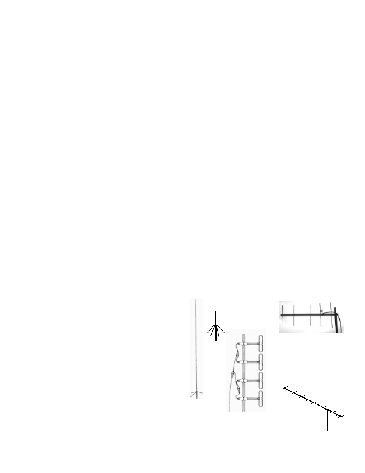
Ground
Plane
OAL 5L-70cm 8 dBd 420450 MHz Yagi Mounts
horzontal or vertical.
31” boom ideal for portable
& public service use
F718 L or X510NJ
or A
9dBd vertical
omni, 15 to 17 ft.
used at cross band
or inband separate
antenna repeaters
4
Broad band
exposed dipole
vertical 6-9 dBd
omni used at
inband repeaters
with duplexer
DSFO ATV-25 16 dBd
420-450 MHz Yagi,
17 ft boom.

REALIGNMENT OR TRANSMIT FREQ. CHANGE
A frequency not originally ordered with your TC70-20 can be
changed to by plugging in the new xtal and peaking the TXA5-70
board with a voltmeter. The crystals are video carrier freq. /4, 5th
overtone in a HC-25 holder, .005% tolerance. Push the crystal all
the way down into the socket, and then lift back up slightly so that
the crystal can does not short out against the sockets. Refer to the
TXA5-70 board layout on page 7 for test point locations.
Start at the oscillator (C1) and peak progressively toward the
output. All peaking is done with no video connected and the 1K
pedestal pot at maximum power (full CCW). Use a small insulated
tuning tool on the trimmer caps, and slowly rotate in the slot with
very little downward pressure. The voltages shown are typical
minimums. When you are done peaking all trimmers, reset the 1K
pedestal pot to 75% of the value read at the output test point on the
DMTR board, or 60% of the maximum power read on a power meter
(Bird 25E slug or SX-1000 20W scale). The blanking pedestal is
now clamped to the proper level regardless of the applied video
level.
20
watt s
Set ped.
pot 60%
(12) watts
Modulated Vide o Waveform
100% (watts) p.e.p.
60% power
Vide o
75% blanking
pedestal
sy ncsync
(vol tage)
100% sync
70% Black
40% grey
12% whi te
zer o car ri er
The sound subcarrier frequency is set to 4500 kHz +/- 2 kHz
by the 18µH variable inductor with a counter at the FMA5-F output.
Do not try to reset by listening to a TV set as it will give a false peak,
be off in another TV, or give a crosshatch beat in color video if off
frequency or injection level set too high. The amount of injection
is set by the 500 Ohm pot to 15 to 18 dB down from the sync tip (≤-
15 dBc) by us with a spectrum analyzer. Deviation pot is set at the
25 kHz broadcast standard by the soft limiter.
PEDESTAL & LINEAR AMPLIFIER SETUP
The RF power and video pedestal must be reset to compensate
for the differences between transmitters, amplifier gain curves, and
applied DC voltage changes. Failure to make this setup will result
in rolling or unstable video. You will need to readjust the TC70-20
for a supply voltage that is more than 1/2 Volt different than the
13.8 Vdc used to set it up at the factory, Do not run the TC70-20
from the same supply as an external amplifier or you may get
distorted video or instabilities. Follow this set up procedure:
1. Disconnect any video input to the TC70-20.
2. Connect amp output through a RF power meter to dummy
load or antenna with no more than 10% reflected power.
3. Turn pedestal pot on TXA5-70 board to full CCW and RF
power pot to full CW - see page 7 for locations.
4. Turn on transmitter and quickly set the RF out pot for no
more than 90% of rated amp peak envelope power - ie.
DXP-U150 = 135 watts, D1010N-ATV = 90 watts.
5. Set pedestal pot for 60% or the peak power set - ie. if 90
watts, set pedestal for 90x.6=54 watts. For the TC70-20
by itself 22(typical)x.6=13.2 watts.
You may now reconnect the video and set video gain for best
picture as described by a distant station, the transmit monitor output
in this case may no longer be accurate. The monitor level in transmit
will have to be readjusted with the pot on the DMTR board any time
the output power is changed. Usually less video gain is necessary
with an amp; do not over drive into white clipping. The pedestal
control sets the video to sync ratio by clamping the blanking power
level at the set value and stretching the sync tip to maximum
regardless of the video gain control or average picture contrast.
We suggest the Diamond SX-1000 multirange RF power meter or
Bird power meter with appropriate slugs for barefoot and amplifier
setups. Never adjust the pedestal with video connected.
The sync tip power (peak envelope power) on the TC70-20 and
any linear amps will still be the max power you read before the
reduction to the blanking pedestal due to the sync stretcher in the
modulator. Any further reading of an “average” reading RF Wattmeter
is meaningless as they do not respond normally to modulation above
100 kHz and the reading will vary depending on the picture contrast.
An all white picture will give the lowest reading, and an all black one
will read about the same as the blanking set up.
0
-10
-20
dBc
-30
-40
-50
Sound ±4.5MHz (-15dBc) Color ±3.58MHz (-22dBc)
S
CC
-5 -4 -3 -2 -1 0 +1 +2 +3 +4 +5 MHz
Typical ATV Spectrum
V
Video carrier
S
The spectrum above is normal AM double sideband from an
ATV transmitter . If your transmissions interfere with other band users
near your lower sideband sound or color subcarriers, you may need
a VSB filter in your antenna line. We suggest the DCI 8 pole VSB
filter available from us. However, it will also attenuate any other
frequency you may wish to tune to, so is only good for one frequency
simplex or crossband repeater operation. Vestigial sideband filtering
should not be confused with SSB, it’s completely different. With
VSB, nothing is done to the carrier and less than 5% of the sideband
power is cut off. VSB only rolls off the lower sideband starting at .75
MHz below the video carrier frequency. FCC defines VSB as having
the lower color and sound sidebands down more than 60 dB below
the peak power (see spectrum above and also fig. 6 on pg 20-3 in
the 1987 to 1994 or fig. 12.61 in the 1995-2001 ARRL Handbooks).
The only way to achieve this with amateur “linear” amplifiers is to put
a VSB filter in the antenna line. VSB filtering is not necessary at the
transmitter except in the case of a repeater near the band edge below
424.6 MHz, in the presence of other transmitters with the possibility
of creating transmitter intermod, or if there are other mode users
near you that receive interference from your LSB subcarriers.
70 cm ATV FREQUENCIES
Frequencies and antenna polarities vary in different parts of the
country. ATV repeaters and Frequency Coordination Councils are
listed in the ARRL Repeater Directory . There are only 2 A TV channels
available in the 70 cm band without the possibility of mutual
interference. Broadcast TV skips adjacent channels in a given area
to avoid interference. The separation then is 12 MHz. If there is an
inband repeater, then simplex is sometimes run on the repeater input,
or another frequency with the possible interference accepted. Some
areas have gone to crossband repeat with the output on either the
33 cm band (923.25) or 23 cm band (1253.25) which frees up one of
the two 70cm frequencies for simplex, and the other for repeater
input. Also the simplex frequency can be used for full duplex operation
with another station on 910.25 or 1289.25 MHz. Crossband repeat
or duplex allows receiving your own video back with just the addition
of another antenna and downconverter.
The primary 70 cm frequencies are 439.25 and 434.0 in the
USA depending on the level of FM repeater activity in the 440-450
MHz segment, or satellite operation in the 435-438 MHz segment.
With a video carrier on 439.25, you can give interference to FM
stations on your color and sound subcarrier frequencies around
442.83 and 443.75, and receive interference in the picture from those
transmitting below 444 MHz. With 434.0, your sideband energy will
be about 40 dB down at 435 MHz which will only interfere with satellite
stations very close to you, but their transmissions will tear up your
received video. The most popular secondary simplex frequency is
426.25. This frequency is usually clear in most areas and is shared
with point to point links and control channels between 420-431 MHz.
5

DO NOT ADJUST ANY OF THESE BOARDS WITHOUT PROPER TEST EQUIPMENT AND EXPERIENCE
To Power on Switch
To TVC-2G +
RG-174
To TXA5
To FMA5 +
To TXA5 T+
TX Lamp
Monitor video out
R
PTL
T
To Video gain pot CCW
To TVC-2G In
Antenna N
Connector
RF Power out test
point >-10Vdc
+13.8
To PA5
To
TVC-2G
Antenna
M57716 Power Module
To PA5
+T
220
.5 W
10 mF
1K
DMTR70-10
(c) 1998
2N2222A
4.5 MHz
Trap
120
To TXA5
To FMA5
PTL
+R
RF
relay
Test
100K
Point
-Vdc
1N5711
10 pF
C
5K
Video
Level
adjust
10 mF
power
relay
video
relay
10 mF
10 mF
+
33K
10 mF
+
+
33K
+
+
video in
33 pF
22K
PA5 Power Module
board - no adjustments
5A
+13.8
pin 2
Monitor
pin 1
Video
out
16 Vz
1N5353B 5W
To +
DMTR
DMTR-10 Relay and Monitor Board
Transmit monitor video level out is adjusted with the 5K pot on the bottom of the board. Reset to 1 Vp-p if you reset the RF power output.
It may work in your monitor if a linear amp is added. The 100K resistor test point can be used with a DC voltmeter for final RF peaking and
pedestal setting if a RF Watt meter is not available. The Trimmer cap C is peaked and need not be touched, do not detune this cap to
reduce power, it could blow the power module - use the RF power pot on the TXA5-70 board - see next page. The extra unused +R and
+T pads can be used for controlling external devices by jumpering to the open power connector pins 3 or 4 (1/2 Amp max).
+8V
L3
L2
6.5V
C3
470
C2
1KL1
47
1K
+8V
220
100
C4
1
5
MV2105
10K
2.2K
1mF
1K
.3V
Varicap
Tuning
0 to 8 V
+
.01
G2
G1
NE253
Mixer
3.3K
100
10K
100
.01
10K
Band
Spread
.8V
100
.47
.001
22
15
1N914
.01
100
+11 to
+8V
10mF
14 Vdc
78L08
8V reg
++
1mF
TVC-2G rev F 70 CM
ATV Downconverter
(c) PC Electronics 1998
(2)
75 Ohm
Ch3 out
16Vz
1N4745
TVC-2G Downconverter
ext
AGC
.001
50 Ohm
70 CM
Antenna
Input
OSC
353 - 394 MHz
.01
220
C1
10K
2N2222
NE253
Preamp
3.3K
47
220
G2
G1
1V 1V
.1
MPSH81
6V
No adjustments. The 10K pot on the front panel varies the varicap voltage between 0 (lowest frequency) and 8 Vdc to change the
frequency. C1, 2 and 3 are bandpass filters peaked for the 420-444 MHz ATV frequencies. C4 sets the local oscillator frequency. C4 is
factory set to roughly 434 MHz into CH3 with the knob between 3 and 5. No adjustments are necessary if CH2 or 4 is used as there is
plenty of excess tuning range. If you believe the GaAsfets have popped from lightning, etc., check with a Voltmeter at the Source and Gate
2 leads. G2 ≤ S voltage. Gennerally they may be popped if the source or gate 2 is above 2 Vdc.
470
78L08
pF
8V reg
500
4.5 MHz
Output
100
FMA5-F2 ©1998
P.C. Electronics
+1
+11 to
15 Vdc
16
Vz
470 pf
Lo Z
Mic
input
Line
Audio
input
1
10
+
10K
+
10Kt
470
470 pF
15K
Mic Gain
50K
5.6K
6
5
+
10
22K
10
+
Mic Amp
1K
7
4
10K
.01
10K
3
+
2
1
1N914 (2)
1K
75uS
Pre-emphasis
Audio Amp
+8 Vreg
8
TLO82CP
100K
4.7K
Dev.
adj.
1
4.6Vdc
10K
10K
+
470
pF
10
10K
470
pF
MV
2115
18uH
Tune
4500
kHz
470
2N2222
470
pF
10uH
470
10K
pF
VCO Buffer
.01
Inj.
Level
MPF102
1K
C1
120
pF
FMA5-F Sound Subcarrier Generator
The front panel 10K Line audio and 50K Mic audio pots vary the audio gain. The switch on the line audio pot turns on power to this board.
The 10K deviation pot on the board is roughly set to just start soft limiting at 25 kHz deviation and hard limit around 40 kHz deviation. The
500 Ohm subcarrier injection pot is set to no less than 15 dB down from peak sync by us with a spectrum analyzer. If set any higher, the
4.5 MHz subcarrier will give increased sync buzz from limiting during white video periods and sync time as well as crosshatch intermod
beat with color video. If set too low, the sound will drop out with increasingly snowy pictures or not give best sound when the downconverter
is tuned for best picture at the other end. Sound will normally drop out when color does in snowy conditions. The 18 uH inductor is set to
within 2 kHz of 4.500 MHz with a frequency counter connected to the subcarrier output pad.
Electronics
66
6 (c) 1999 P. C.
66

Video
In
To DMTR
5 MHz Lowpass Filter
F2
Video gain
100 ohm
F1
+T
Osc Peak C1
>.5 Vdc
1st Doubler
Peak C2 & C3
>1.4 Vdc
2nd Doubler
Peak C4 & C5
>.2 Vdc
Note: Voltages noted
are with 13.8 Vdc
applied, pedestal full
ccw; 12Vdc will be
less.
RF power
output pot
To PA5 amp
Final Peak C6 &
C7 -1 to -3 Vdc
Blanking Pedestal pot
Sync Stretcher
330
.001
4.7K
22K
.05
100
1M
220
1M
100
100
1st Doubler 2nd Doubler
68K
L2
RF2
2N5770
C2
osc
tp
4.7K
>.5V
.001
100
relay
F
Xtal
VIDEO
INPUT
10K
4.7K
10
V
.001
330
22K
+
100
Video
gain
OSC
RF1
2N5770
1K
2N2222
4.7K
L1
C1
10
10
56
TXA5-70 Exciter Modulator -
P
1K
2N2907
2.2K
1N751
Blanking
220
5.1Vz
Pedistal
Adj
2N4124
+
22
.001
L3 L5
1N914
220
1N914
33
220
15K
RF3
2N5770
C3
1K
18
220
+
.1
1N914
C4
1K
100
2N2222
33
L4
3.3K
C5
10
22
270
100
Final
22
2N2219A
Modulator
RF4
MPS911
>.3V
tp
220
22
+
1K
33
Sync
tp
>1.4V
100
220
4.5 MHz
Sound
Input220
TXA5-70b ATV TRANSMITTER
© 1997
220
.22
L6
C6 C7
16Vz
10
1N5711
4.7K
14.0 Vdc
-
RF OUT
50 Ohms
56
Level
250
RF TP
-1to -3V
+
+12 to
1N4745
Read this completely before touching any adjustments.
To FMA5 sound board
RG174
5A
3A
3AG
3AG
Fuse
fuse
DMTR
TVC-2G
PA5
FMA5-F
TXA5-70
There are two pots on this board that you may have occasion to readjust. The blanking pedestal pot is common to all the P. C. Electronics
transmitters. It is used to accurately set the video to sync ratio whether running barefoot or through an external amplifier or by itself. The
sync stretcher circuit clamps to the video blanking pedestal to keep a constant sync and blanking level regardless of video gain and
average picture level. To set the blanking pedestal, disconnect any video input, and connect a RF power meter (Bird with 25E / 100E slug
or Diamond SX1000) in the antenna line after any amp. Turn the 1K pedestal pot full CCW . T urn on the transmitter and quickly (<20 sec.)
set the peak power output with the 250 Ohm RF Level pot (to no more than 90% of maximum output for external amps; multiply max power
noted by .9). This will be your constant peak envelope power. Do not exceed 150 Watts if driving a Teletec DXP-U150. If driving other
amps, make sure you don’t exceed the maximum rated input drive at any time by measuring and presetting the TC70-20’s power level
before connecting the amp. Next reduce the p.e.p. power by 60% (multiply the peak envelope power just set by .6) using the 1K pedestal
pot. This will be the constant blanking pedestal power. Now you can connect video and adjust the front panel video gain pot for best
picture just before white limiting. Do not adjust any board pots or trimmer caps with video connected, and only adjust power out with the
RF level pot, never any of the trimmer capacitors - it could cause instability and poor linearity in the video.
Frequency Change or RF Realignment. Your TC70-20 is aligned at the factory to accept crystals (Fo/4) for any frequency you specify
from 426.25 to 439.25. P.e.p. power should not be more than 10% different between these two frequencies. If you plug in a new crystal,
or one frequency seems not to come on or is intermittent, first push the crystal down and then raise it back up just a little to make sure its
case is not shorting out on the socket. Then, with a DC voltmeter connected to the 100 Ohm resistor oscillator test point, slowly peak for
max voltage (typically >.6 Vdc) with the highest frequency crystal. Then switch to the lowest frequency crystal and check to see that the
voltage is within .1 Vdc of the higher frequency crystal reading. Slowly rotate C1 with an insulated tuning tool toward more capacity to bring
it in if necessary. You should not have to peak any of the other variable capacitors, but if the power out of the TC70-20 (not an external
amp) is different by more than 10% you may want to. In this case, you will have to unplug any video and set the pedestal pot to maximum
power output. Then starting at C2 & 3 peak at its multiplier test point with a voltmeter for maximum on the highest frequency , and then bring
the lower frequency up to with in 10% without going below 1.4 Vdc. Then peak C4 & C5 at its doubler Test point (>.3 Vdc), followed by C6
& C7 peaking at the RF TP for negative voltage. Then reset the RF level and Pedestal pot per the previous procedure.
77
7
77
(c) 1999 P. C. Electronics

WHAT CAN YOU PUT ON ATV?
Any T echnician class or higher radio amateur can transmit
ATV to other amateurs on amateur frequencies above 420
MHz, and Novices on 1270-1295 MHz. Besides showing you
and your gear in the shack, you can show and describe your
latest projects in detail, copy schematics, help debug
computer programs, put on your own home video tapes and
movies, computer graphics & games, repeat Space Shuttle
video from the NASA Select satellite channel, repeat SSTV,
RTTY, Packet, etc. to ATV. You can repeat computer
generated weather radar or satellite video for skywarn and
emergency amateur radio groups. Transmit the local radio
club meeting to those that physically can’t make it. Virtually
any non-commercial video from your camera, VCR or NTSC
compatible computer is simply plugged into the video in jack
and sent exactly as you would see it on the local monitor.
ATV is a big help for getting an overview of an operational
situation during parades, races, search and rescue, major
fires, and other disasters. Public service is a great way to
have fun with your ATV gear. Your transmissions must be
controlled by licensed hams, and directed primarily to another
ham. ATV has been used for public service in vehicles,
portable, boats, airplanes and helicopters. For portable, the
TC70-20 can be carried in a knap-sack, a short coax run to
a 1/4 wave ground plane clipped onto a headset/mic, and
plugged into a 6 Amp/hr gel cell battery. The OAL 5L-70cm
beam is only 31” long, 8 dB gain and its >60 degree
beamwidth cuts down the multipath ghost problem from
reflected RF coming in from the sides and back at the receive
site. 2 Radio Shack 5 ft mast sections and tripod fit easily in
the car with the beam for portable operations.
If used in an aircraft for fun or remote damage assessment
with emergency service groups or CAP , run RG400 (available
at businesses that do cellular telephone installation in cars)
or RG142 coax instead of RG58 coax to the antenna.
Ordinary coax will put noise in the picture due to vibration
modulation - there is enough attenuation change as the ohmic
contact between adjacent strands of the coax shield rub back
and forth. Use only a stiff quarter-wave spike on the bottom
of the aircraft to minimize radiation nulls as the plane banks
- do not use gain antennas. FAA certified antennas for the
amateur bands are available from Comant (562) 946-6694.
Snow free line of sight DX with the quarter wave on the belly
to a 9-10 dB omni (F718) on the ground is 25 miles.
WHAT CAN’T YOU DO WITH ATV?
All the FCC rules and regs in part 97 apply (47 CFR). The
ARRL FCC Rule Book is a good reference that explains all
these by practical examples. All amateur transmissions must
be directed to another amateur with few exceptions for control, tests or emergencies (97.1 1 1, 97.215, 97.401 to 97.405).
Therefore ATV cannot be used for surveillance purposes for
personal, business or law enforcement. You cannot “broadcast” (97.1 13) to a non-amateur or retransmit any other radio
service (except Space Shuttle Video and audio) or music.
A TV cannot be used as a cheap link for local cable or public
access community TV systems, church services, video or
movie production directly or indirectly . Basically you cannot
use Amateur radio to further any business purpose, profit or
non-profit or activity contrary to Federal, State, or local law .
There are other frequencies and licensing for these purposes.
Teachers who are licensed radio Amateurs can transmit to
another amateur, classroom to classroom, or to other schools
as long as it is used to demonstrate Amateur radio or radio
communications or for fun between school radio clubs. They
cannot, however, transmit normal lessons, broadcast school
sporting events or other school business.
STATION IDENTIFICA TION.
You must identify with your call letters every 10 minutes
and at the end of every transmission (97.119). This can be
done by voice on the sound subcarrier or by call letters on the
screen. If done on video, the letters must be large enough to
be easily seen in the picture. Many just put up a large call
sign with black letters on white board on the shack wall in
normal camera view. You can get fancy by overlaying your
call letters over the camera video with a GVID board in the
video line, or computer generated special effects. In weak
signal conditions, it has been found that large, fat black letters
on a white background which fill the whole screen show up
best in the snow. Others use a computer and switch between
the camera and a generated graphic call sign.
LIGHTS, CAMERA, ACTION.
Proper lighting makes a big difference in picture contrast
quality . It is best to have a light at, or just behind, the camera
directed at the subject to remove shadows caused by the usual
overhead lights. Do not crank up the video gain control to
bring up dark areas as the bright areas will over modulate
giving sync buzz, instability and may splatter the band.
With color cameras, try to use only one type of lighting...do
not mix sun light through a window, incandescent and
florescent lamps with each other or the colors will shift as you
swing the camera. Set the color camera white balance every
time you first turn on the camera by aiming at an all white
sheet illuminated by the same type of light in the scenes you
will be showing. For outdoors, especially public service events,
CCD or MOS cameras are preferred over vidicon types as
they will not normally be damaged if accidentally aimed at
the sun.
Since a picture is worth a thousand words, you will note
that you will run out of subject matter faster than voice modes.
So the more people you can get on A TV, the greater the things
to show. Pick an ATV net night and publicize it at your local
radio club by having them include the time, video and 2 meter
talkback frequency in the club newsletter. Better yet start off
by giving them a talk/demo. Once they see their first picture
they are usually hooked - this can be as simple as connecting
an outside 440 MHz antenna of the same polarity you are
using to a cable ready TV set to cable channel 57 through 60
- these cable channels correspond to frequencies between
421.25 to 439.25 MHz and are different than over the air
broadcast channels. To keep the net interesting vary each
net night of the month with a theme: everybody has to show
a family member, a project, wear a hat, make a new call ID
sign, a pet, 1-2 minute personal video tape, etc. - ENJOY!
For more general or background information on A TV check
out page 12.46 in the 1995-2000 ARRL Handbook and
Amateur Television Quarterly Magazine. There are also ATV
remailers on the internet - contact us at: tom@hamtv.com
for the latest internet addresses and ATV repeater group web
pages. Our web site: www.hamtv.com
8
(c) 2000 P. C. Electronics
 Loading...