


PCE Instruments UK Ltd.
Units 12/13 Southpoint Business Park
Ensign Way, Southampton
Hampshire
United Kingdom, SO31 4RF
Phone: +44 ( 0 ) 2380 98703 0
Fax: +44 ( 0 ) 2380 98703 9
E-Mail: info@industrial-needs.com
Homepage: http://www.industrial-needs.com
Web: http://www.pce-instruments.com/english/


C96IB001ML-A 3
SG-Ultra Max
Portable Density Meter
From Firmware Version V1.79
Instruction Manual

4 C96IB001ML-A
EN
While every precaution has been taken in the preparation of this document, Eagle
Eye Power Soltuions (EEPS) assumes no responsibility for technical or printing
errors or omissions. Nor is any liability assumed for damages resulting from the
use of the information contained in this instruction manual. EEPS does not make a
commitment to update the information in this manual. Specifications are subject
to change without notice.
All rights reserved (including translation). No part of this document may be translated,
reproduced or distributed in any form (print, photocopy, microfilm or any other
process) without the prior written permission of Eagle Eye Power . Trade marks may
be used in this instruction manual without being marked as such. These are the
property of their respective owners and are legally protected.
Contact: PCE Instruments UK Ltd.
South Point Business Park, Ensign Way Units 12/13
SO31 4RF Southampton
Tel: +44 ( 0 ) 2380 987 03 0
Fax: +44 ( 0 ) 2380 987 03 9
E-mail: info@industrial-needs.com
Web: www.pce-instruments.com/english

C96IB001ML-A 5
EN
Contents
1 About the Instruction Manual ........................... ..................................... ... .......8
2 Safety Instructions ..................................... .....................................................10
3 Measuring Principle ........................................................................................12
4 SG-Ultra Max - an Overview ..........................................................................13
5 Checking the Supplied Parts .........................................................................14
6 Description of the Instrument ........................................................................17
6.1 Front View ............................................................................................... 17
6.2 Rear View ...............................................................................................19
6.3 Display .................................................................................................... 20
7 Operating the SG-Ultra Max ...........................................................................22
7.1 Connecting the Filling Tube ....................................................................22
7.2 Attaching the Syringe Adapter ................................................................ 22
7.3 Switching the Instrument On ...................................................................23
7.4 Switching the Instrument Off ...................................................................23
8 Defining the Basic Settings ............................................................................24
8.1 Language Settings ..................................................................................24
8.2 Units ........................................................................................................ 24
8.3 Sound Settings ....................................................................................... 24
8.4 Energy Saving Mode .............................................................................. 24
8.5 Backlight ................................................................................................. 25
8.6 Contrast Settings .................................................................................... 25
8.7 Allocation of the Softkey Function .......................................................... 25
8.8 Password Protection ...............................................................................26
8.9 Date and Time Settings .......................................................................... 27
9 Exchanging Data with a PC ............................................................................28
9.1 Establishing a Connection to a PC ......................................................... 28
9.2 Exporting Data to a PC ........................................................................... 28
9.3 Importing data from a PC ........................................................................ 29

6 C96IB001ML-A
EN
10 Performing a Measurement ............................................................................30
10.1 Selecting the Measuring Unit ..................................................................31
10.1.1 Categories of Measuring Units .........................................................32
10.1.2 Calculating a Temperature Coefficient .............................................34
10.1.3 Importing Custom Functions .............................................................34
10.2 Selecting Measuring Methods .................................................................35
10.2.1 Entering a New Method ....................................................................35
10.2.2 Entering Method Lists .......................................................................35
10.2.3 Editing a Method ...............................................................................37
10.2.4 Deleting Methods ..............................................................................37
10.2.5 Selecting a Method ...........................................................................37
10.3 Assigning a Sample ID ............................................................................37
10.3.1 Entering the Sample ID ....................................................................37
10.3.2 Entering Sample ID Lists ..................................................................38
10.3.3 Editing Sample IDs ...........................................................................39
10.3.4 Deleting Sample IDs .........................................................................39
10.3.5 Selecting a Sample ID ......................................................................39
10.4 Selecting the Measurement Mode ...........................................................40
10.5 Using the RFID Function (Only for Versions with RFID Interface) ..........40
10.5.1 Preconditions for Using RFID ...........................................................40
10.5.2 Allocating RFID Tags ........................................................................41
10.5.3 Programming RFID Tags ..................................................................42
10.5.4 Erasing RFID Tags ...........................................................................42
10.5.5 Reading RFID Information ................................................................43
10.5.6 Selecting a Method and/or Sample ID via RFID ...............................43
10.6 Filling Sample ..........................................................................................44
10.6.1 Filling Using the Filling Tube ............................................................44
10.6.2 Filling with the Plastic Syringe ..........................................................44
10.7 Performing a Measurement .....................................................................45
10.7.1 Deleting the Measured Value ...........................................................45
10.7.2 Printing the Measured Value ............................................................46
10.7.3 Emptying the Measuring Cell ............................................................46
10.8 Accessing Saved Measuring Data ..........................................................46
10.9 Exporting Measuring Data to a PC ..........................................................47
10.10 Printing the Saved Measuring Data .........................................................48
10.11 Deleting the Saved Measuring Data ........................................................48

C96IB001ML-A 7
EN
11 Cleaning and Storing the Instrument ............................................................50
11.1 Cleaning the Measuring Cell ................................................................... 50
11.2 Cleaning the Filling Pump ....................................................................... 50
11.3 Cleaning the Pump Housing ...................................................................50
11.4 Cleaning the Housing and Display .......................................................... 51
11.5 Storing the Instrument ............................................................................ 51
12 Maintenance ....................................................................................................52
12.1 Changing the Batteries ........................................................................... 52
12.2 Carrying out a Firmware Update ............................................................. 55
12.3 Device Information .................................................................................. 55
13 Readjustment .................................................................................................. 56
13.1 Check Measurement ...............................................................................56
13.2 Water Adjustment ................................................................................... 56
13.3 Custom Adjustment ................................................................................ 57
13.4 Defining an Offset ...................................................................................57
13.5 Restoring to Factory Adjustment ............................................................58
14 Error Messages and Warnings ......................................................................59
15 Technical Data .................................................................................................60
16 Wetted Parts ....................................................................................................61
Appendix A: Density of Water (0 °C to 40 °C) ............................................ ... .....62
Appendix B: Measuring Unit Details ..................................................................63
Appendix C: Firmware Versions .........................................................................66
Appendix D: Menu Tree ........................................................................................67

8 C96IB001ML-A
EN
1 About the Instruction Manual
This instruction manual informs you about the installation and the safe handling and
use of the product. Pay special attention to the safety instructions and warnings in the
manual and on the product.
The instruction manual is a part of the product. Keep this instruction manual for the
complete working life of the product and make sure it is easily accessible to all people
involved with the product.
Conventions for safety messages
The following conventions for safety messages are used in this instruction manual:
DANGER
Danger indicates a hazardous situation which, if not avoided, will result
in death or serious injury.
WARNING
Warning indicates a hazardous situation which, if not avoided, could
result in death or serious injury.
CAUTION
Caution indicates a hazardous situation which, if not avoided, could
result in minor or moderate injury.
NOTICE Notice indicates a situation which, if not avoided, could result in
damage to property.
TIP Tip gives extra information about the situation at hand.

C96IB001ML-A 9
EN
Typographical conventions
The following typographical conventions are used in this instruction manual:
Convention Description
<key> The names of keys and buttons are
written inside angle brackets.
"Menu Level 1 > Menu Level 2" Menu paths are written in bold, inside
straight quotation marks. The menu
levels are connected using a closing
angle bracket.

10 C96IB001ML-A
EN
2 Safety Instructions
• Read this instruction manual before using the portable density meter
SG-Ultra Max.
• Follow all hints and instructions contained in this instruction manual to ensure
the correct use and safe functioning of SG-Ultra Max.
Liability
• This instruction manual does not claim to address all safety issues associated
with the use of the instrument and samples. It is your responsibility to establish
health and safety practices and determine the applicability of regulatory
limitations.
• EEPS only warrants the proper functioning of SG-Ultra Max if no
adjustments have been made to the mechanics, electronics, and firmware.
• Only use SG-Ultra Max for the purpose described in this instruction manual.
EEPS is not liable for damages caused by incorrect use of SG-Ultra Max.
Installation and use
• SG-UltraMax and SG-Ultra Max Tag&Log are not explosion-proof instruments
and therefore must not be operated in areas with risk of explosion.
• Never remove the pump lock and battery cover in hazardous areas. Only
exchange the batteries outside of hazardous areas.
• The installation procedure shall only be carried out by authorized personnel who
are familiar with the installation instructions.
• Do not use any accessories or wearing parts other than those supplied or
approved by EEPS.
• Make sure all operators are trained to use the instrument safely and correctly
before starting any applicable operations.
• In case of damage or malfunction, do not continue operating SG-Ultra Max. Do
not operate the instrument under conditions which could result in damage to goods
and/or injuries and loss of life.
• Check SG-Ultra Max for chemical resistance to the samples and cleaning liquids.
• Do not expose the instrument to temperatures below 0 °C (32 °F) if water is
contained in the measuring cell or pump (freezing water will cause rupture of the
measuring cell).
• SG-UltraMax is not insulated against high voltages. Measuring samples under high
voltage (e.g. in energized battery banks) bears the risk of an electric shock.
Define appropriate testing procedures and safety measures to protect yourself
from any electric shock.

C96IB001ML-A 11
EN
Use in hazardous areas
• Only instruments with ATEX marking may be used in hazardous areas.
• By labelling the intrinsically safe SG-Ultra Max (types SG-Ultra Max Version 3 Ex
and SG-Ultra Max Version 3 Ex Petrol) with the type plate according to ATEX,
EEPS confirms that the instrument conforms with all documents submitted for
receiving the certificate of conformity. Therefore, do not subject the intrinsically
safe SG-Ultra Max to alterations of any kind.
• The intrinsically safe SG-Ultra Max (types SG-Ultra Max Version 3 Ex and SG-Ultra
Max Version 3 Ex Petrol) must not be isolated from earth potential when operated or
placed within hazardous areas. Grounding is done via the hand of the user or a
conductible board. Make sure that the contact to earth potential is not prevented
by using isolating gloves.
• The intrinsically safe SG-Ultra Max Ex and SG-Ultra Max Ex Petrol (types SG-Ultra
Max Version 3 Ex and SG-Ultra Max Version 3 Ex Petrol) can be used according to
ATEX marking II 2 G Ex ib IIC T4. All instructions given in the certificate of
conformity have to be followed (see Appendix D).
• Never remove the pump lock and battery cover in hazardous areas. Only
exchange the batteries outside of hazardous areas.
• Only use the permitted alkaline battery type EN91 (LR06, AA) from Energizer
Industrial.
Maintenance and service
• The results delivered by SG-Ultra Max not only depend on the correct functioning of
the instrument, but also on various other factors. We therefore recommend you
have the results checked (e.g. plausibility tested) by skilled personnel before
consequential actions are taken based on the results.
• Service and repair procedures may only be carried out by authorized personnel
or by EEPS.
• If your instruments needs repair, contact your local EEPS representative.
Disposal
• Concerning the disposal of SG-Ultra Max observe the legal requirements in your
country.
Precautions for highly flammable samples and cleanin g liquids
• Observe and adhere to your national safety regulations for handling the
measured samples (e.g. use of safety goggles, gloves, respiratory protection
etc.).
• Only store the minimum required amount of sample, cleaning liquids and other
inflammable materials near SG-Ultra Max.

12 C96IB001ML-A
EN
• Do not leave sample/rinsing containers uncovered. Clean all spillages
immediately.
• Make sure that the setup location is sufficiently ventilated. The environment of
SG-Ultra Max must be kept free of flammable gases and vapors.
• Supply a fire extinguisher.
3 Measuring Principle
Definition of density
The density ρ of a sample is defined as its mass divided by its volume:
Density is a temperature-dependent measuring unit.
The oscillating U-tube principle
The sample is introduced into a U-shaped borosilicate glass tube that is being excited
to vibrate at its characteristic frequency electronically. The characteristic frequency
changes depending on the density of the sample. Through determination of the
characteristic frequency the density of the sample can be calculated. Due to the
temperature dependency of the density value, the temperature of the sample has to
be determined precisely.
Concentration measurement
In binary mixtures, the density of the mixture is a function of its composition. Thus, by
using density/concentration tables, the density value of a binary mixture can be used
to calculate its composition.
This is also possible with so-called quasi binary mixtures. These are mixtures
containing two major components and some additional ones which are present in very
small concentrations compared to the two main components. Many decarbonated soft
drinks, for example, can be considered to be quasi binary mixtures of sugar in water
because the concentration of flavors and acids are very small compared to sugar and
water. Thus, the sugar concentration can be measured with a density meter.
ρ
m
V
-----=

C96IB001ML-A 13
EN
4 SG-Ultra Max - an Overview
The portable density meter SG-Ultra Max measures the density of liquids in g/cm3 or kg/m3
according to the oscillating U-tube principle. Apart from density you can select various
further measuring units (relative density, density at reference temperature,
concentrations). A temperature sensor measures the sample temperature right at the
measuring cell. The temperature is displayed and can be used internally for automatic
temperature compensation of the density reading if required.
Owing to the lightweight and compact design one can easily perform measurements
of usually difficult accessible samples. The backlight of the display ensures clear
visibility of results, even in dark surroundings. The backlight of the oscillator at the
same time enables to observe the filling process in detail.
Samples are filled into the measuring cell using the built-in pipette-style pump or a
syringe. You can allocate sample IDs to your samples for easier identification. You can
also define and store different measuring methods allowing acceleration of repeatedly
performed standard measurements.
SG-Ultra Max is operated via seven keys. 1024 measuring data including date, time
and sample ID can be stored in the memory of the SG-Ultra Max density meter and
can be recalled, exported to a PC or printed later. The transfer of the stored measuring
data to a printer or PC is done wireless using an infrared interface (IrDA).
The product version SG-Ultra Max Tag&Log is additionally equipped with an RFID
interface. Via this interface, sample IDs and/or methods can be uniquely linked to an
RFID tag. Later on, by reading the RFID tag, you can switch fast and easily between
different sample IDs and methods which further increases the efficiency of your
measuring process.
The intrinsically safe product versions SG-Ultra Max Ex and SG-Ultra Max Ex Petrol
(ATEX marking II 2 G Ex ib IIC T4) are suitable for use within potentially explosive
areas. The SG-Ultra Max Ex is ideal for chemical applications and measuring battery
acid. The SG-Ultra Max Ex Petrol comes with a special housing for petrochemical
applications, esistant to petrols and similar solvents.
The product versions SG-Ultra Max Ex and SG-Ultra Max Ex Petrol are also equipped
with an RFID interface.

14 C96IB001ML-A
EN
5 Checking the Supplied Parts
SG-Ultra Max was tested and packed carefully before shipment. However, damage
may occur during transport.
1. Keep the packaging material (box, foam piece) for possible returns and further
questions from the transport company or insurance company.
2. Check the delivery for completion by comparing the supplied parts to those
given in Table 5.1.
3. If a part is missing, contact your EEPS representative.
4. If a part is damaged, contact the transport company and your EEPS
representative.
Fig. 5 - 1 Supplied items
1 ... DSG-Ultra Max density meter
2 ... IrDA USB adapter (optional)
3 ... Plastic syringes 2 mL
4 ... Luer adapter 1/4" UNF (for syringe f
illing)
5 ... Filling tube (standard 180 mm)
1
3
4
5
2

C96IB001ML-A 15
EN
Table 5.1: Supplied parts
Symbol Pcs. Article Description Mat. No.
1 SG-Ultra Max portable density meter
or SG-Ultra Max Tag&Log portable
density meter or
SG-Ultra Max portable density meter
or SG-Ultra Max Ex Petrol portable
density meter
84138 or
87448
or
87450 or
87451
1 Instruction Manual
English 88155
1 Filling tube (standard 180 mm) 68527
1 Luer adapter 1/4" UNF (for syringe
filling)
64792
10 Plastic syringes 2 mL 58802
1 Allen wrench 2.5 mm DIN 911 58263

16 C96IB001ML-A
EN
Table 5.2: Optional parts
Article Description Mat. No.
ABS disc tag 30 mm, 5 mm hole R 92412
ABS disc tag 30 mm, 5 mm hole R/W 88443
Black laundry tag 30 mm R 92413
Black laundry tag 30 mm R/W 88444
White PVC sticker disc tag 30 mm R/W 88445
White PVC sticker disc tag 30 mm R 92414
Carrying case for SG-Ultra Max 88506
Custom function for SG-Ultra Max 88974
DKD calibration SG-Ultra Max 88153
Filling tube PTFE, length: 600 mm 78503
IrDA USB adapter LCS-8141 88085
Printer CMP-10-E5 RS232C/IrDA 87817
Set wristband for SG-Ultra Max 92416

C96IB001ML-A 17
EN
6 Description of the Instrument
6.1 Front View
Fig. 6 - 1 Front view of SG-Ultra Max
1 ... Built-in pump
2 ... Screw plug
3 ... Measuring cell
4 ... Softkeys
5 ... Operating keys
6 ... RFID interface (only for SG-Ultra Max Tag&Log, SG-Ultra Max Ex and
SG-Ultra Max Ex Petrol)
7 ... Graphical, monochrome LC display
1
2
345
6
7

18 C96IB001ML-A
EN
Fig. 6 - 2 Top view of SG-Ultra Max
1 ... Built-in pump
2 ... Fixing screw of the pump lock
3 ... Pump lock
4 ... Infrared interface (IrDA)
Keys at the front side
For switching the instrument on and off.
For deleting measuring data, entries and characters during an
entry.
Softkeys for selecting menu items and for navigation. The function
of the right softkey can be configured.
Arrow keys for navigation within the menu and for the entry of
characters.
TIP For faster up and down navigation, keep the arrow keys pressed.
1
23
4

C96IB001ML-A 19
EN
6.2 Rear View
Fig. 6 - 3 Rear view of SG-Ultra Max
1 ... Data storage key
2 ... Type plate with serial number
3 ... Registration number and ATEX marking (only for SG-Ultra Max Ex and
SG-Ultra Max E x Petrol)
4 ... Custom functions (optional)
5 ... Mark for the correct battery insertion
6 ... Calibration number (optional)
Key at the rear side
For starting a measurement and storing results in the memory
1
2
56
4
3
20 C96IB001ML-A
EN
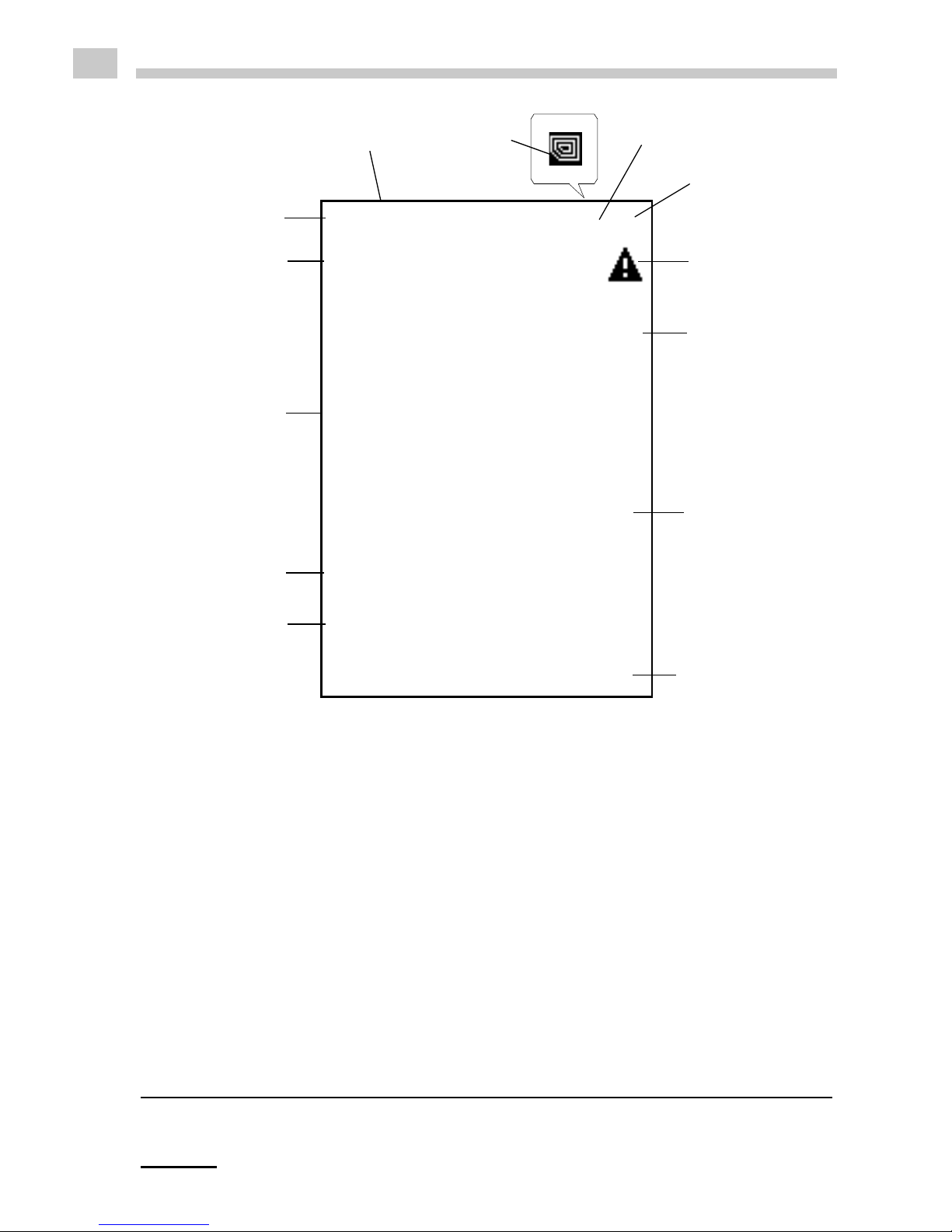
6.3 Display
Fig. 6 - 4 Display of SG-Ultra Max
1 ... Information header
2 ... Date and time
3 ... Symbol for infrared data transfer (3a) or RFID symbol1 (3b)
4 ... Symbol for battery charge status
5 ... Warning sign
6 ... Measuring value
7 ... Sample temperature °C/°F
8 ... Softkey configuration
9 ... Sample ID
10 ... Method
11 ... Custom offset
12 ... Measuring unit
1 Only for SG-Ultra Max versions with RFID interface
1
2
4
5
6
7
8
9
10
11
12
3a3b

C96IB001ML-A 21
EN
Symbols on the display
The infrared data transfer symbol is shown on the information header
when data is imported or exported via the IrDA interface.
The RFID symbol is shown on the information header when it is
possible to allocate an RFID tag to a method or sample ID and when an
RFID tag is read while the instrument displays the main screen.
Furthermore, methods and/or sample IDs with an allocated RFID tag
are marked with this symbol when listed.
The battery charge status symbol informs you about the battery charge
status of your instrument. For further information on different charge
status symbols and their meanings, see Chapter 12.1.
The warning sign indicates that a measured value is outside range
specifications. The warning sign is always shown together with an
information (press the right softkey) stating the warning type (for details
about warning types, see Chapter 14).
TIP You can change between the <Info> softkey which is displayed together
with the warning sign and the original softkey configuration by pressing the
arrow keys.

22 C96IB001ML-A
EN
7 Operating the SG-Ultra Max
7.1 Connecting the Filling Tube
• Screw in the filling tube by hand until you feel some resistance against turning.
Do not use any tools for screwing in the filling tube.
Fig. 7 - 1 Connecting the filling tube
7.2 Attaching the Syringe Adapter
1. Remove the screw plug at the side of the instrument.
2. Screw in the Luer adapter (see Chapter 5) by hand until you feel some
resistance against turning. Do not use any tools for screwing in the Luer adapter.

C96IB001ML-A 23
EN
7.3 Switching the Instrument On
• To switch the instrument on, press the key.
After showing the welcome screen, SG-Ultra Max immediately switches to the
main screen (measuring mode). Now you can start with the measuring process.
7.4 Switching the Instrument Off
• To switch the instrument off, press the key until "Power Off" is displayed.
If the instrument is in the energy saving mode (see Chapter 8.4), SG-Ultra Max
switches automatically off after 3, 5 or 10 minutes inactivity (depending on the setting).

24 C96IB001ML-A
EN
8 Defining the Basic Settings
8.1 Language Settings
You can choose between two different menu languages:
1. Press <Menu> and select "Setup > Language".
2. Select the preferred language and press <OK>.
8.2 Units
1. Press <Menu> and select "Setup > Units".
2. Select g/cm
3
or kg/m
3
as the density unit and press <OK>.
3. Select °C or °F as the temperature unit and press <Save>.
8.3 Sound Settings
When sound is enabled, SG-Ultra Max beeps when it is switched on and off and
when a key is pressed.
When sound is disabled, the instrument only beeps when it is switched on and off.
1. Press <Menu> and select "Setup > Beep".
2. Select the preferred setting (Beep on/off) and press <Save>.
8.4 Energy Saving Mode
Enabling the energy saving mode lowers the power consumption of the instrument
and thus extends battery life. When the energy saving mode is enabled, the
instrument will automatically switch itself off after 3, 5 or 10 minutes of inactivity.
When the energy saving mode is disabled, the instrument will remain switched on
until it is turned off using the key.
1. Press <Menu> and select "Setup > Energy Saving".
2. Select the preferred setting (Off, 3, 5 or 10 minutes) and press <Save>.

C96IB001ML-A 25
EN
8.5 Backlight
The LC display and the oscillator are equipped with a backlight. The backlight ensures
that even under bad lighting conditions the measuring results and menu options are
easily readable. The backlight of the oscillator enables you to observe the filling
process.
You can choose between "Auto", "Off" and "On":
1. Press <Menu> and select "Setup > Backlight".
2. Select the preferred setting (Auto, Off, On) and press <Save>.
8.6 Contrast Settings
The display contrast can be freely adjusted to suit your preference.
1. Press <Menu> and select "Setup > Display Contrast".
2. Select the preferred setting (-8 to +8) and press <Save>.
8.7 Allocation of the Softkey Function
On the front side of SG-Ultra Max are two softkeys. When the instrument displays the
main screen, the left softkey always takes you to the main menu. The right softkey can be
allocated with one out of three predefined functions. The allocated function is only
available in the main screen.
Auto The backlight automatically turns on when a key is pressed or when
a new sample is filled into the measuring cell. To activate the
backlight without accessing the menu, press an arrow key. The
backlight switches off automatically after 30 seconds.
Off The backlight is permanently off.
On The backlight is permanently on.
TIP Having the backlight turned on permanently will shorten battery life.

26 C96IB001ML-A
EN
The functions available are "RFID
2
", "Store" and "Print".
1. Press <Menu> and select "Setup > Softkey".
2. Select the preferred setting (RFID, Store, Print) and press <Save>.
8.8 Password Protection
You can protect your instrument with a password according to your demands. If the
password protection is enabled, the password needs to be entered before changing
the settings, before performing an adjustment and before selecting a measuring unit.
For performing measurements as well as entering, changing or deleting measuring
methods or sample IDs no password entry is required.
You can anytime change the password later on or disable password protection
entirely. Keep your password information safe.
To set, change or delete a password
1. Press <Menu> and select "Setup > Set Password".
2. If your instrument is already password protected, enter your current password.
3. Enter your new password using the arrow keys and press <Continue>.
4. If you want to disable the password protection entirely, enter <0000> as the new
password and press <Continue>.
5. Enter the password again and press <Save>.
RFID Enables programming and reading of RFID tags for the purpose
of quick sample identification.
Store
Provides the same functionality as the key on the back of
the instrument and starts and stores a measurement.
Print Enables immediate print-out of the measured value using the
IrDA interface.
2 Only for SG-Ultra Max versions with RFID interface

C96IB001ML-A 27
EN
8.9 Date and Time Settings
During operation the information header always displays the current date and time.
To set date and time
1. Press <Menu> and select "Setup > Date and Time > Set Date and Time".
2. Enter the current day, month and year using the arrow keys and confirm each of
your selections by pressing <OK>.
The cursor moves to the next value to be set.
3. Press <Save>.
Now the time settings are displayed on the screen.
4. Repeat the procedure to enter the current time and press <Save>.
To set the date format
1. Press <Menu> and select "Setup > Date and Time > Date Format".
2. Select the preferred date format and press <OK>.
To set the time format
1. Press <Menu> and select "Setup > Date and Time > Time Format".
2. Select the preferred time format and press <OK>.

28 C96IB001ML-A
EN
9 Exchanging Data with a PC
Your SG-Ultra Max features wireless data transfer from and to a PC via the integrated
IrDA interface. You need a PC with an infrared interface or a PC with an IrDA USB adapter
installed and connected. Contact your EEPS representative if you need an IrDA
USB adapter for your PC.
9.1 Establishing a Connection to a PC
1. If your PC has no IrDA interface, install the IrDA USB adapter on your PC.
2. Hold the IrDA interface of SG-Ultra Max to the IrDA interface of your PC to
establish communication between the two instruments.
3. Continue with Chapter 9.2 or Chapter 9.3.
9.2 Exporting Data to a PC
The following data can be exported from your instrument to a PC:
• Measured data (see Chapter 10.9 for further options how to export measured
data)
• Custom functions (custom-specific measuring units)
• Adjustment data (currently valid adjustment)
• Device information
• Sample ID list
• Method list
• System settings (backup copy of instrument)
1. Establish a connection between the SG-Ultra Max and the PC (see Chapter 9.1).
2. Press <Menu> and select "Setup > Import / Export > Send to PC".
3. Select the type of data you want to export.
A dialog window appears on your PC asking if you want to accept the file.
4. Click <Yes>.
The selected data are transferred and filed on the desktop.

C96IB001ML-A 29
EN
9.3 Importing data from a PC
The following data can be imported from a PC to your instrument:
• Custom functions
• Sample ID list
• Method list
• Firmware updates
1. Establish a connection between the SG-Ultra Max and the PC (see Chapter 9.1).
2. Press <Menu> and select "Setup > Import / Export > Receive from PC".
3. On the PC, right mouse-click on the file you want to send and select "Send to >
A nearby computer".
The selected file is transferred to the instrument.

30 C96IB001ML-A
EN
10 Performing a Measurement
General instructions for measuring
• Make sure that the measuring cell is filled free from gas bubbles. Possible
reasons for gas bubbles in the measuring cell are:
• Gas bubbles in the sample
• Leaky connection of the filling tube, the pump or the screw plug
• Make sure that the measuring cell is fully filled.
• Make sure that the sample temperature does not deviate too strongly from the
ambient temperature.
WARNING
Handling samples with temperatures of more than 70 °C bears the
danger of heavy burns.
• Make sure you wear protective clothes or ensure alternative
protection from burns when handling high temperature samples.
WARNING
SG-Ultra Max not insulated against high voltages. Measuring samples
under high voltage (e.g. in energized battery banks) bears the risk of an
electric shock.
• Define appropriate testing procedures and safety measures to
protect yourself from any electric shock.
NOTICE Before performing a measurement, make sure that the wetted parts
are resistant to the sample (see Chapter 16).
NOTICE Sample containing dissolved CO
2
will cause bubbles within the
measuring cell with the effect of invalid measurement results. Make
sure your sample is degassed carefully.
Degassing a sample can be done by:
• boiling the sample for several minutes,
• stirring the sample for 5 to 15 minutes until no bubbling occurs
any more or
• putting the sample for approximately 5 to 10 minutes into an
ultrasonic bath.

C96IB001ML-A 31
EN
If the sample measured is outside the temperature specifications (0 to +40 ° C),
the display shows the warning sign until the sample has reached a measurable
temperature. If the measured value is nevertheless saved, it is shown with an
exclamation mark.
• Make sure to carefully clean the instrument after each measurement series to
avoid deposits in the measuring cell.
• Make sure that suitable solvents for cleaning are available.
10.1 Selecting the Measuring Unit
For measuring your samples you can choose between a number of predefined
measuring units or you can import custom functions into the instrument and select one
of them as the measuring unit. Contact your EEPS representative to obtain a
custom function from EEPS.
All measuring units are derived from the density of the sample at the measured
temperature.
1. Press <Menu> and select "Measuring Units".
The list of the predefined measuring units is displayed.
2. Select the preferred measuring unit and press <OK>.
Some measuring units contain subitems with options to be selected.
3. Select the preferred option and press <OK>.
TIP Your filled sample is continuously measured and the measuring result is
displayed. By storing the measuring result, you can print it or export it to a
PC later.

32 C96IB001ML-A
EN
10.1.1 Categories of Measuring Units
For further details, see Appendix B.
Meas.
units
Options Description
Density Density Density at the displayed measuring
temperature in g/cm
3
or kg/m3.
Density @ xx °C:
α (g/cm3/K)
Density at the chosen reference
temperature in g/cm3 or kg/m3. The
temperature influence is compensated by
the set temperature coefficient α.
Specific Gravity SG:
SG Temp. (°C or °F)
α (g/cm
3
/K)
Specific gravity is the density of the
sample (at the chosen reference
temperature) divided by the density of
water (at the chosen reference
temperature). The temperature influence
is compensated by the set temperature
coefficient α (g/cm
3
/K).
Alcohol Alcohol % v/v @ 20 °C Concentration of an ethanol/water mixture
in % by volume at 20 °C.
Alcohol % w/w Concentration of a mixture of alcohol and
water in % by weight.
Alcohol US @ 60 °F
(°Proof)
Degrees Proof at 60 °F.
API
a
API Gravity A
API Gravity B
API Gravity D
API number for the product group referred
to the reference temperature of 15 °C or
60 °F.
Product group A: Crude oil
Product group B: Fuels
Product group D: Lubricants
API SG A
API SG B
API SG D
Specific gravity for the product group
referred to the reference temperature of
15 °C or 60 °F.
API Density A
API Density B
API Density D
Density of the product group in g/cm
3
with
regard to the reference temperature of
15 °C or 60 °F.
a
Depending on the set temperature unit (°C or °F), the API values are
automatically displayed @ 15 °C or @ 60 °F.

C96IB001ML-A 33
EN
Baumé
α (g/cm
3
/K)
Degrees Baumé at 60 °F.
Temperature influence is compensated by
the set temperature coefficient α.
For determining degree Baumé there are
two different calculation methods
depending on whether the density is
above or below the density of water.
Depending on the density of the
measured liquid, SG-Ultra Max
automatically switches between the two
calculation methods.
H2SO4 H2SO4 % w/w Concentration of sulfuric acid or battery
acid in % by weight.
H2SO4 @ 20 °C Density of sulfuric acid or battery acid at
20 °C.
Sugar Brix Degrees Brix (sucrose concentration in %
by weight).
Extract (°Plato) Degrees Plato.
Custom
Functions
-- Optional custom functions. Contact your
EEPS representative to obtain a
custom function.
Period -- Period value of the oscillator at the
measuring temperature.
Raw data -- Period value and resistance of the
temperature sensor (only for service
purposes).
Meas.
units
Options Description

34 C96IB001ML-A
EN
10.1.2 Calculating a Temperature Coefficient
A temperature coefficient α (g/cm3/K) is needed for the calculation of some measuring
units at a certain reference temperature.
The temperature coefficient can be calculated as follows:
Typical temperature coefficients:
10.1.3 Importing Custom Functions
In addition to the predefined measuring units, you can import up to ten custom
functions to the instrument and select one of these as the measuring unit.
To do this, the coefficients for the calculation of your measuring unit need to be
transferred to the instrument in the correct format. Contact your EEPS
representative if you want to import one or more additional measuring units to your
instrument. You will receive a file with the custom functions in the correct format from
EEPS.
For how to import custom functions, see Chapter 9.
ρ
1
... Density at temperature T1
ρ
2
... Density at temperature T2
Numerous aqueous solutions from 0 to approx. 20 % 0.0003
Numerous aqueous solutions from 10 to approx. 50 % 0.0005
Numerous organic solutions 0.001
Temperature coefficient
ρ
1ρ2
–
T
1T2
–
------------------
=

C96IB001ML-A 35
EN
10.2 Selecting Measuring Methods
Application of the method selection
You can define and store measuring methods in your SG-Ultra Max, providing a
great contribution to a more efficient organization of your measuring process.
A stored measuring method may contain the following kinds of information:
• Measuring unit
• Offset value
• Temperature coefficient
• Number of the RFID tag
3
You can define and name up to 20 different measuring methods.
If you own several SG-Ultra Max instruments, you can import the same method list
to all instruments.
10.2.1 Entering a New Method
1. Select the preferred measuring unit (see Chapter 10.1) and, if necessary, the
custom offset (see Chapter 13.4).
2. Press <Menu> and select "Methods > Enter new Method".
3. Enter the measuring method's name using the arrow keys.
4. Navigate to the tick symbol using the arrow keys and press <Save>.
10.2.2 Entering Method Lists
If you plan to set up or edit large method lists, you can do so conveniently on the PC
and then import the list to SG-Ultra Max. If you own several SG-Ultra Max instruments,
you can import the same method list to all instruments to get several identical instruments.
To gain insight into the format to be used, first define one or two methods on the
instrument (see Chapter 10.2.1) and then transfer these to the PC. After doing that
you can conveniently enter further methods in the same format and import these into
the instrument.
3 Only for SG-Ultra Max versions with RFID interface
TIP If you keep an arrow key pressed, the cursor automatically stops at the tick
symbol.

36 C96IB001ML-A
EN
For how to import method lists, see Chapter 9.
Entering the data on the PC also allows for using additional characters. The
instrument supports the space character and the following characters:
Method list template
The following table explains the lines of a method list:
TIP Importing a new method list automatically deletes the existing method list.
! "#$%&' ( ) *+, - . /0123456789: ;<=>?
@ABCDEFGH I J KLMNOPQRSTUVWXYZ [ \ ] ^
_` abcde f gh i j k lmnopqr s tuvwxyz { | }
~ ° ² ³µДЦЬЯдйць
<SG-Ultra Max>
<METHODLIST>
<METHOD>
<NAME>ALCOHOL</NAME> Name of the first method: Alcohol
<RFID>0100.7916.3A16</RFID> RFID tag 0100.7916.3A16 allocated
<UNIT>11</UNIT> Measuring unit: Alcohol % v/v
</METHOD>
<METHOD>
<NAME>SG</NAME> Name of the second method: SG
<RFID></RFID> No RFID tag allocated
<UNIT>3</UNIT> Measuring unit: Specific Gravity SG
<ALPHA>0.00124</ALPHA> Temperature coefficient: 0.00124
<TEMP1>20</TEMP1> Temperature 1: 20
<TEMP2>4</TEMP2> Temperature 2: 4
</METHOD>
</METHODLIST>
</SG-Ultra Max>

C96IB001ML-A 37
EN
10.2.3 Editing a Method
1. Press <Menu> and choose "Methods > Edit Method".
2. Select the method you want to edit and press <OK>.
3. For changing a method name, see Chapter 10.2.1; for allocating an RFID tag,
see Chapter 10.5.2; for programming an RFID tag, see Chapter 10.5.3.
10.2.4 Deleting Methods
1. Press <Menu> and select "Methods > Edit Method".
2. Select the method to be deleted and press .
3. Select <Delete Selected> to delete only the selected method or <Delete all> to
delete all methods.
4. Press <Delete> when asked if you really want to delete the selected method(s).
10.2.5 Selecting a Method
1. Press <Menu> and choose "Methods > Select Method".
All stored methods are displayed.
2. Select the preferred method and press <OK>.
10.3 Assigning a Sample ID
You can assign different sample IDs to samples. This function helps to uniquely
assign measuring data to
• samples (sample identification)
• users who performed the measurement (user identification)
• the measuring point where the sample was taken etc.
You can save up to 100 different sample IDs.
10.3.1 Entering the Sample ID
1. Press <Menu> and select "Sample-ID > Enter new ID".
2. Use the arrow keys to enter the sample ID.
3. Browse with the arrow keys to the tick symbol and press <Save>.

38 C96IB001ML-A
EN
Example: By naming your sample ID "Tank 1 - ##", you will get "Tank 1 - 01", "Tank 1
- 02", etc. as sample ID on the main screen. By naming your sample "#### - Tank 1",
you will get "0001 - Tank 1", "0002 - Tank 1", etc. as sample ID on the main screen.
10.3.2 Entering Sample ID Lists
If you plan to set up or edit large sample ID lists, you can do so conveniently on the
PC and then import the list to SG-Ultra Max. If you own several SG-Ultra Max
instruments, you can import the same sample ID list to all instruments to get severa
identical instruments.
To gain insight into the format to be used, first define one or two sample IDs on the
instrument (see Chapter 10.3.1) and then transfer these to the PC. After doing that
you can conveniently enter further sample IDs in the same format and import these
into the instrument.
For how to import sample ID lists, see Chapter 9.
TIP If you keep an arrow key pressed, the cursor automatically stops at the tick
symbol.
TIP If you enter a new sample ID and only select the tick symbol without
entering letters for the ID, the sample ID is automatically given the name
<empty>. The 4-digit consecutive number of the measuring data is then
used as the ID.
TIP You can count the measurements performed with one sample ID. By
entering one to four "#" signs at any position of your sample ID, you will
see the one- to four-digit subcounter of measured values as part of your
sample ID on the main screen. The subcounter will be set to (000)1 as
soon as you either select another sample ID or select the same sample ID
again.
TIP If you reset the subcounter within a sample ID by mistake (by selecting the
same sample ID anew), switch the instrument off and on again to proceed
with the next higher subcounter within this sample ID.

C96IB001ML-A 39
EN
Sample ID list
The following table explains each line of a sample ID list:
10.3.3 Editing Sample IDs
1. Press <Menu> and select "Sample-ID > Edit ID".
2. Select the ID you want to change and press <OK>.
3. For changing the sample ID, see Chapter 10.3.1; for allocating an RFID tag, see
Chapter 10.5.2; for programming an RFID tag, see Chapter 10.5.3.
10.3.4 Deleting Sample IDs
1. Press <Menu> and select "Sample-ID > Edit ID".
2. Select the sample ID you want to delete and press .
3. Select <Delete selected ID> to delete only the selected sample ID or <Delete all
IDs> to delete all sample IDs.
4. Press <Delete> when asked if you really want to delete the selected ID(s).
10.3.5 Selecting a Sample ID
1. Press <Menu> and select "Sample-ID > Select ID".
All saved sample IDs are displayed.
2. Select the required sample ID and press <OK>.
<SG-Ultra Max>
<IDLIST>
<ID>
<NAME>ETHANOL</NAME> Name of the first ID: <Ethanol>
<RFID>0100.7916.3A16</RFID> RFID Tag 0100.7916.3A16 allocated
</ID>
<ID>
<NAME>WATER</NAME> Name of the second ID: <Water>
<RFID></RFID> No RFID tag has been allocated
</ID>
</IDLIST>
</SG-Ultra Max>

40 C96IB001ML-A
EN
10.4 Selecting the Measurement Mode
SG-Ultra Max provides three different measurement modes - "Precise", "Fast" and
"Manual". According to the measurement mode selected, different stability criteria
have to be fulfilled before the result is stored. The stability criterion is always related
to the temperature:
• When the measurement mode "Precise" is selected, the result is stored as soon
as the measured temperature value stays within 0.2 K for 10 seconds. This
measurement mode delivers the most accurate results, but may take a longer
time in case the sample temperature differs greatly from the ambient
temperature.
• When the measurement mode "Fast" is selected, the result is stored as soon as
the measured temperature value stays within 0.4 K for 10 seconds. This
measurement mode delivers quicker results than the "Precise" mode, but as the
density is highly temperature dependent, the measured result is not that
accurate.
• The measurement mode "Manual" enables you to decide yourself when to store
your measurement result. The result is stored immediately after pressing the
<Store> key on the backside of the instrument.
1. Press <Menu> and select "Measurement Mode".
2. Select the preferred setting (Precise, Fast, Manual) and press <Save>.
10.5 Using the RFID Function (Only for Versions with RFID Interface)
The product versions SG-Ultra Max Tag&Log, SG-Ultra Max Ex and SG-Ultra Max
Ex Petrol are equipped with an RFID interface, enabling you to uniquely link an
RFID tag to a method and/or sample ID. The RFID tag can either be allocated to a
sample ID and/ or method on the instrument or can be programmed accordingly.
10.5.1 Preconditions for Using RF ID
The reading range of the RFID receiver integrated in SG-Ultra Max is about 2 cm. The
RFID tag has to be situated within this area to enable data exchange with SG-Ultra Max.
TIP The larger the diameter of a tag, the larger is the reading range.

C96IB001ML-A 41
EN
The following types of RFID tags were tested by EEPS for usage. Both tested tag
types are available at EEPS.
Furthermore, several other LF tags (low frequency tags, 125 kHz) may be compatible
in the "Read only" mode. See Chapter 10.5.5 for details on how to check RFID tags
for compatibility.
10.5.2 Allocating RFID Tags
Allocation of an RFID tag is done by reading the unique identification number of the
tag via the RFID interface of SG-Ultra Max and by allocating this identification number
to a method and/or sample ID on the instrument. Allocation is done exclusively on the
instrument and no programming of the RFID tag is done. For this, RFID tags with
read-only functionality are sufficient.
You can allocate an RFID tag during entering a new method (see Chapter 10.2.1) or
sample ID (see Chapter 10.3.1) as well as during editing a method (see Chapter
10.2.3) or sample ID (see Chapter 10.3.3).
Measuring methods and sample IDs that have an allocated RFID tag are marked with
the RFID symbol .
1. Go to the corresponding menu as described in the appropriate chapter.
2. Hold the RFID tag to the RFID interface of the instrument until the RFID tag
number is displayed.
3. You can now enter further characters, if required.
4. Navigate to the tick symbol using the arrow keys and press <Save>.
An RFID tag may only be allocated to one method and/or sample ID. If you try to
allocate an RFID tag to more than one method and/or sample ID, the message "RFID
in use" is displayed. In this case, choose another RFID tag for this method or sample
ID.
If you try to allocate an RFID tag a second time to the same sample ID or method,
"RFID matches" is displayed.
Read only passive RFID tags (unique
tags)
Disc tag, 30 mm, Chip EM4102,
125 kHz
Read/write passive RFID tags Disc tag, 30 mm, Chip Hitag S2048,
125 kHz

42 C96IB001ML-A
EN
10.5.3 Programming RFID Tags
Besides allocation of RFID tags to sample IDs and/or methods on the instrument (see
Chapter 10.5.2), SG-Ultra Max versions with RFID interface provide the option to
write the sample ID and/or method to an RFID tag. Using this programming feature
makes you independent regarding the amount of sample IDs and methods used as no
sample ID list or method list has to be stored permanently on the instrument. One
method and/ or one sample ID can be stored on the RFID tag.
1. Enter the sample IDs (see Chapter 10.3.1) and/or methods (see Chapter 10.2.1)
or import a sample ID list (see Chapter 10.3.2) and/or method list (see Chapter
10.2.2) from your PC.
2. Press <Menu> and select "Sample-ID > Send ID to RFID" or "Methods >
Send Method to RFID".
The sample ID list or method list appears on your screen.
3. Move the cursor to the first sample ID or method you want to send to an RFID
tag using the arrow keys.
4. Hold the RFID tag to the RFID interface of the instrument until the RFID tag
number is displayed.
The tag is now programmed with the according sample ID or method.
5. Repeat this procedure for the other sample IDs and/or methods you want to
store on other RFID tags.
6. After all sample IDs and/or methods have been sent to RFID tags, you can
delete the sample ID list (see Chapter 9.3.5) and/or method list (see Chapter
9.2.5) from the instrument.
10.5.4 Erasing RFID Tags
In case a mistake occurred during programming of a tag or if you want to use the tag
for another sample ID and/or method, you have the possibility to delete the sample ID
and/or method from the tag.
1. Press <Menu> and select "Setup > RFID > Erase RFID".
2. Hold the RFID tag to the RFID interface of the instrument until "RFID Erased" is
displayed.

C96IB001ML-A 43
EN
10.5.5 Reading RFID Information
Reading the RFID information helps you to identify an RFID tag in case the tags got
mixed up, or you want to check if the tag was programmed correctly, or you want to
check the compatibility of a tag type with SG-Ultra Max versions with RFID interface.
The RFID information states details about:
• tag number
• tag type (writeable yes/no)
• sample ID allocated to or stored on the tag
• method allocated to or stored on the tag
1. Press <Menu> and select "Setup > RFID > RFID Information".
2. Hold the RFID tag to the RFID interface of the instrument until the RFID
information is displayed.
3. Hold the next RFID tag to the RFID interface of the instrument until the RFID
information is displayed or exit the "RFID Information" menu.
10.5.6 Selecting a Method and/or Sample ID via RFID
This way of selection is only available if one or more methods and/or sample IDs have
been allocated to an RFID tag (see Chapter 10.5.2) or if one or more RFID tags have
been programmed with a method and/or sample ID (see Chapter 10.5.3).
1. Allocate the RFID function to the softkey (see Chapter 8.7)
2. When the instrument displays the main screen, press the <RFID> softkey.
The message "Reading RFID" is displayed.
3. Hold the allocated or programmed RFID tag to the RFID interface of the
instrument.
TIP If you want to check the compatibility of a tag type to the instrument, see if
the RFID number ("RFID") is stated within the RFID information. In case it
is displayed, the tag is compatible, if it is not displayed, the tag type is not
compatible.
TIP When reading an RFID tag, which is neither allocated to a sample ID or
method on the instrument nor programmed with a sample ID or method,
the unique tag number will be used as sample ID automatically.

A-LM100BI69C44
EN
The method and/or sample ID allocated to or stored on the RFID tag will
automatically be used for the following measurements.
10.6 Filling Sample
Depending on the viscosity of the sample, you can fill the measuring cell using the
filling tube or the plastic syringe. When filling highly viscous samples, we recommend
using the plastic syringe.
10.6.1 Filling Using the Filling Tube
1. Press down the pump lever as far as it will go (see Fig. 10 - 1).
2. Submerge the filling tube in the sample.
3. Slowly release the pump lever.
Fig. 10 - 1 Filling sample using the fil
ling tube
10.6.2 Fi
lling with the Plastic Syringe
1. Fill the plastic syringe with the sample.
2. Fill the measuring cell through the Luer adapter using the plastic syringe.
NOTICE Do not remove the pump when filling with the plastic syringe.
Otherwise, the system is leaky.

C96IB001ML-A 45
EN
Fig. 10 - 2 Filling sample using the plastic syringe
10.7 Performing a Measurement
1. Select the measuring unit (see Chapter 10.1) or measuring method (see
Chapter 10.2).
2. Define a sample ID (see Chapter 10.3).
3. Fill the measuring cell with the sample.
4. Press the key on the back of SG-Ultra Max.
The measured value is displayed as soon as the result has stabilized. The
measured value with all corresponding data is now saved in the results list.
5. Press <OK> to return to the measuring mode.
10.7.1 Deleting the Measured Value
• Press instead of <OK> when the measured value appears on the
display.
The measured value is deleted and the instrument returns to the measuring
mode.

46 C96IB001ML-A
EN
10.7.2 Printing the Measured Va lue
You can transfer the measured value to a printer via the IrDA interface. For a
compatible printer, contact your EEPS representative.
1. Allocate the softkey the command <Print> (see Chapter 8.7).
2. Switch on the printer with the IrDA interface.
3. Press the <Print> key when the measured value appears on the display.
4. Hold the IrDA interface of SG-Ultra Max to the IrDA interface of the printer to
establish communication between the printer and density meter.
The measured value is printed.
You can also print out all or only the last measuring data (see Chapter 10.10).
10.7.3 Emptying the Measuring Cell
1. Place the filling tube in a vessel which is suitable for sample disposal.
2. Empty the measuring cell by pressing the pump lever.
10.8 Accessing Saved Measuring Data
You can save up to 1024 measuring data directly in the instrument’s memory. If the
memory contains 1024 saved values, further values will overwrite the oldest saved
values. Each saved value is given a consecutive 4-digit number. Using this number
you can see whether the instrument has overwritten old entries. This is the case if the
consecutive number is larger than 1024. If you delete all measuring data, the counter
starts again at 0001.
1. Press <Menu> and select "Measuring Data".
The list of results is displayed (see Fig. 10 - 3).

C96IB001ML-A 47
EN
Fig. 10 - 3 Measuring data
10.9 Exporting Measuring Data to a PC
For how to export measured data, see Chapter 9.
To set the data export format
1. Press <Menu> and select "Setup > Import / Export > Data Format".
You can choose between different format options.
2. Choose the data format, <CSV> or <TXT>, and press <OK>.
3. Choose the delimiter, <,> [comma], <;> [semi-colon] or </> [slash], and press
<OK>.
4. Choose the decimal point, <.> [point] or <,> [comma], and press <OK>.
Your changes are accepted and used for the following data export. The settings
for delimiter and decimal point are only applied with CSV data exports.
To export a single measured value
1. Establish a connection between the SG-Ultra Max and the PC as
described in Chapter 9.1.
2. Press <Menu> and select "Measuring Data".
3. Select the measured value required for export using the arrow keys.
4. Press <Export>.
5. Select <Export Selected> to export the selected measured value to the PC.

48 C96IB001ML-A
EN
A dialog window appears on the PC asking if you want to accept the file.
6. Click <Yes>.
The measured value is transferred and filed on the desktop.
To export all measuring data
1. Establish a connection between the SG-Ultra Max and the PC as
described in Chapter 9.1.
2. Press <Menu> and select "Measuring Data".
3. Press <Export>.
4. Select <Export All> to export the whole list of measuring data to the PC.
A dialog window appears on the PC asking if you want to accept the file.
5. Click <Yes>.
The measuring data are transferred and filed on the desktop.
10.10 Printing the Saved Measuring Data
You can transfer the saved measuring data to a printer via the IrDA interface. For a
compatible printer, contact your EEPS representative.
To print saved measuring data
1. Switch on the printer with the IrDA interface.
2. Press <Menu> and select "Measuring Data".
3. Select the measured value required for printing using the arrow keys.
4. Press <Export>.
5. Select <Print Selected> to print the selected measured value or <Print All> to
print the whole list of measuring data.
6. Hold the IrDA interface of SG-Ultra Max to the IrDA interface of the printer
to allow communication between the printer and the density meter.
10.11 Deleting the Saved Measuring Data
To delete the last measured value
1. Press <Menu> and select "Measuring Data".
2. Select a measured value and press .
3. Select <Delete Last> and press <OK>.
4. Press <Delete> when asked if you really want to delete the last measured value.

C96IB001ML-A 49
EN
To delete all measuring data
1. Press <Menu> and select "Measuring Data".
2. Select a measured value and press .
3. Select <Delete All> and press <OK>.
4. Press <Delete> when asked if you really want to delete all measuring data.

50 C96IB001ML-A
EN
11 Cleaning and Storing the Instrument
11.1 Cleaning the Measuring Cell
Clean the measuring cell with a suitable solvent regularly before and after each
measurement series to ensure the long-term accuracy of your results. If the
measuring cell is not sufficiently cleaned, residue may form in the measuring cell and
lead to inaccurate measurement results. Depending on the application, also cleaning
between measurements may be required.
1. Empty the measuring cell (see Chapter 10.7.3).
2. Fill the measuring cell with a suitable solvent.
3. Pump the solvent through the whole measuring system several times.
4. Empty the measuring cell.
11.2 Cleaning the Filling Pump
Clean the filling pump regularly, depending on your application. If you measure
aggressive samples, e.g. battery acid, clean the filling pump more often.
1. Open the pump lock and remove the pump.
2. Rinse the pump under running tap water while moving the pump piston up and
down.
3. Dry the pump with a lint-free cloth.
4. Insert the pump and close the pump lock.
5. Empty the measuring cell (see Chapter 10.7.3).
11.3 Cleaning the Pump Housing
SG-Ultra Max is completely sealed against the outside and the pump. Therefore,
you can rinse the pump housing with running tap water if the housing is dirty.
1. Open the pump lock and remove the pump.
2. Hold the pump housing under running water and rinse it thoroughly.
3. Insert the pump and close the pump lock.
4. Empty the measuring cell (see Chapter 10.7.3).
NOTICE Make sure the solvent you use for cleaning is suitable. The SG-Ultra
Max pump cylinder is not resistant to aggressive cleaning liquids
such as acetone or methyl ethyl ketone (MEK).

C96IB001ML-A 51
EN
11.4 Cleaning the Housing and Display
To clean the housing and display, use a soft cloth dipped in ethanol or warm water. If
necessary, you can use a mild solvent (pH < 10).
11.5 Storing the Instrument
Before storing the instrument for a longer period of time, clean the measuring cell as
described in Chapter 11.1. This prevents any liquid residues freezing or drying in the
measuring cell, which could destroy the cell or lead to measuring inaccuracies.
For storage lasting less than one day, fill the measuring cell with deionized water or
solvent. If you have filled the liquid via the plastic syringe, leave the syringe in the
adapter to stop the liquid running out.

52 C96IB001ML-A
EN
12 Maintenance
12.1 Changing the Batteries
You can see the status of the battery by looking at the battery symbol in the top righthand corner of the display.
The following status are possible:
When the batteries are almost empty, the warning "Low Battery " is displayed. After
the second warning "Battery Empty", the instrument switches itself off.
If the batteries are flat, you can easily replace them.
Battery is full
Battery is a little low
Battery is low
Battery is empty
WARNING
When opening the battery compartment or exchanging batteries,
sparks may be generated which can cause an explosion or fire in
hazardous areas. Serious injuries are possible.
• Never open the battery cover in hazardous areas.
• Only replace the batteries outside hazardous areas.
NOTICE • Always observe the correct polarity when replacing the
batteries.
• Only use batteries of the same type and with the same level of
battery charge.
• For SG-Ultra Max instruments with ATEX marking (SG-Ultra
Max Ex and SG-Ultra Max Ex Petrol), only use the permitted
alkaline battery type EN91 (LR06, AA) from Energizer Industrial.

35A-LM100BI69C
EN
1. Empty the measuring cell (see Chapter 10.7.3).
2. Open the pump lock and remove the pump.
Fig. 12 - 1 Removing the pump
3. Screw out the screw of the pump lock using an Allen key size 2.5 and remove
the screw.
Fig. 12 - 2 Removing the pump lock screw
4. Remove the pump lock by sliding it outwards.

A-LM100BI69C45
EN
Fig. 12 - 3 Removing the pump lock
5. Use a coin to open the battery cover by turning.
Fig. 12 - 4 Opening the battery cover
6. Remove the flat batteries by turning the instrument upside down.
7. Insert the new batteries. The picture on the back of the instrument shows the
correct positioning of the batteries.
8. Close the battery cover using a coin.
9. Insert the pump lock again and slide it back to the original position. Make sure
you slide the pump lock in the correct direction.
10. Close the pump lock again using the Allen screw.
11. Inser
t the pump again.
12. Clos
e the pump lock.
The instrument is ready for operation.
13. Check that the instrument is working properly by switching it on and checking
the display.

C96IB001ML-A 55
EN
12.2 Carrying out a Firmware Update
Your EEPS representative will inform you when a new firmware update for your
SG-Ultra Max is available. After receiving the update file, you can import it into the
instrument.
1. Establish a connection between the SG-Ultra Max and the PC as
described in Chapter 9.1.
2. Import the firmware file as described in Chapter 9.3.
After the successful file import, SG-Ultra Max checks the validity of the update file.
3. Press <OK> to start the installation when "Import valid" is shown.
The progress bar shows you the progress of the installation. After successful
installation the instrument switches itself back on.
12.3 Device Information
Information about the instrument is saved in the instrument and can be accessed or
exported at any time. This information includes the following:
• Manufacturer
• Instrument name
• Serial number
• Instrument status:
• Measuring data: xxxx/1024
• IDs: xxx/100
• Methods: xx/20
• Firmware version
• Date of the firmware version
• Bootloader version
• Date of the bootloader version
• Hardware status
• RFID module version
• Press <Menu> and select "Setup > Device Information".
The device information is displayed.
See Chapter 9.2 for how to export the device information to a PC.

56 C96IB001ML-A
EN
13 Readjustment
If the measuring cell is not sufficiently cleaned, residue can form in the measuring cell.
This can be noticed if the density values for deionized water begin to deviate.
Therefore, perform regularly check measurements with deionized water.
If the density values for water deviate by more than ±0.001 g/cm
3
at the given
temperature from the table values (see Appendix A), then a readjustment is required.
A readjustment is only possible if the calculated difference between the measured
and the theoretical value is smaller than 0.01 g/cm
3
and the temperature of the water
is between 15 and 25 °C.
13.1 Check Measurement
1. Clean the measuring cell as described in Chapter 11.1 and rinse the measuring
cell until no more solvent residues are present.
2. Select the measuring unit "Density" (see Chapter 10.1).
3. Fill the measuring cell with deionized water and perform a measurement (see
Chapter 10.6 and 10.7).
4. Compare the measured density value with the table values (see Appendix A).
5. If the measured density value deviates more than ±0.001 g/cm
3
from the table
value, perform a readjustment.
13.2 Water Adjustment
One option is to readjust using deionized water.
1. Clean the measuring cell as described in Chapter 11.1 and rinse the measuring
cell until no more solvent residues are present.
2. Press <Menu> and select "Adjustment > Water Adjustment".
3. Fill the measuring cell with deionized water at approx. 20 °C (15 to 25 °C)
without bubbles.
4. Confirm with <OK> that the measuring cell is filled with deionized water.
The density value of the filled deionized water is now measured and compared
with the adjustment data. The display shows the calculated deviation (Delta) in
g/cm
3
.
5. Press <OK> to activate the new adjustment.

C96IB001ML-A 57
EN
13.3 Custom Adjustment
You can also use any other reference liquid with a known density at 20 °C and known
temperature coefficient for your readjustment.
We recommend using the customer adjustment e.g. if you measure only liquids in a
specific density range (e.g. high density) and want to yield more accurate results in
this range.
1. Clean the measuring cell as described in Chapter 11.1 and rinse the measuring
cell until no more solvent residues are present.
2. Press <Menu> and select "Adjustment > Custom Adjustment".
3. Fill the measuring cell with reference liquid at approx. 20 °C (15 to 25 °C)
without bubbles.
4. Confirm with <OK> that the measuring cell is filled with reference liquid.
5. Enter the density of your reference liquid at the stated reference temperature
using the arrow keys and press <Save>.
6. Enter the temperature coefficient of your reference liquid and press <Save>.
The density of the filled reference liquid is now measured and compared with the
entered density for the reference liquid at 20 °C. The display shows the
calculated deviation (Delta) in g/cm
3
.
7. Press <OK> to activate the new adjustment.
13.4 Defining an Offset
You can define an offset for your measurement. This is automatically added to each
measured value. The offset value always refers to the current measuring unit and is
deleted when you change to another measuring unit. If you have selected a method,
the set offset is saved with the method.
1. Press <Menu> and select "Adjustment > Custom Offset".
2. Enter your offset value and press <Save>.
TIP The offset value saved with a method can also be changed later on.

58 C96IB001ML-A
EN
13.5 Restoring to Factory Adjustment
If you want to undo all your adjustments, you can restore the factory adjustment.
1. Press <Menu> and select "Adjustment > Factory Adjustment".
The display shows: "Are you sure that you want to reset to factory adjustment?"
2. Press <OK> to restore the factory adjustment.
The factory adjustment is restored.

C96IB001ML-A 59
EN
14 Error Messages and Warnings
Error message Cause
Out of Specification The measured sample temperature is outside the
specifications.
Out of Range The measured value is outside the specified range.
Possible reasons:
• The temperature is too high or too low.
• The density is too high or too low.
• The measured value is invalid.
Temperature Range The temperature of the reference liquid for
readjustment is outside the temperature
specifications (+15 to +25 °C).
Density Range The density of deionized water at 20 °C measured
during readjustment is outside the allowed limits
(tolerance 0.01 g/cm
3
).
Criterion The density of deionized water at 20 °C measured
during readjustment deviates from factory
adjustment by more than 0.01 g/cm
3
.
Low Battery The battery is almost empty.
Battery Empty The battery is empty.
Error 01 The temperature is invalid.
Error 02 The period is invalid.
Error 03 SG-Ultra Max has no adjustment data.
Error 04 Calculation error.
NOTICE If the error messages "Error 01" to "Error 04" occur, send in your
instrument for service.

60 C96IB001ML-A
EN
15 Technical Data
Measuring range:
Density:
0 to 3 g/cm
3
Temperature: 0 to 40 °C (32 to 104 °F)
Viscosity: 0 to approx. 1000 mPa·s
Accuracy:
Density
a
: 0.001 g/cm
3
Temperature: 0.2 °C (0.4 °F)
Repeatability, s. d.:
Density:
0.0005 g/cm
3
Temperature: 0.1 °C (0.2 °F)
Resolution:
Density:
0.0001 g/cm
3
Temperature: 0.1 °C (0.1 °F)
Sample volume: approx. 2 mL
Sample temperature: 0 to 100 °C (32 to 212 °F)
Ambient temperature
b
:
-10 to +50 °C (14 to 122 °F)
Storage temperaturec:
-20 to +70 °C (-4 to 158 °F)
Humidity: 5 to 90 % relative air humidity, non-
condensing
Protection class: IP54 (use in light rain or snow possible)
Display: LCD monochrome, graphical, 41 x 55
mm, 160 x 240 pixel
Data memory: 1024 measuring data
Interfaces:
SG-Ultra Max:
SG-Ultra Max Tag&Log, SG-Ultra Max
Ex and SG-Ultra Max Ex Petrol:
IrOBEX/IrLPT
IrOBEX/IrLPT, RFID
Power supply:
Battery type: Alkaline battery 1.5V, type EN91 (LR06,
AA) from Energizer Industrial
Battery life: > 100 hours
Dimensions
d
:
140 x 138 x 27 mm
(5.5 x 5.4 x 1.1 inches)

C96IB001ML-A 61
EN
16 Wetted Parts
The following materials are in contact with samples and the cleaning liquids.
Weight (incl. batteries):
SG-Ultra Max:
SG-Ultra Max Tag&Log, SG-Ultra Max Ex:
SG-Ultra Max Ex Petrol:
345 g (12.2 ounces)
351 g (12.4 ounces)
396 g (14.0 ounces)
a Viscosity < 100 mPa·s, density range 0 to 2 g/cm
3
b The sample must not freeze in the oscillator.
c Empty the measuring cell before storing the instrument.
d Without pump and filling tube
Material Part
Borosilicate glass Measuring cell, pump cylinder
Kalrez O-ring for SG-Ultra Max Ex Petrol
POM (Polyoxymethylene) Faradex Housing for SG-Ultra Max Ex Petrol
PP (Polypropylene) Faradex MS002 Housing for SG-Ultra Max, SG-Ultra
Max Tag&Log and SG-Ultra Max Ex
PVDF (Polyvinylidene fluoride) Connection block, bolt
Viton O-ring for SG-Ultra Max, SG-Ultra Max
Tag&Log and SG-Ultra Max Ex
62 C96IB001ML-A
EN
Appendix A: Density of Water4 (0 °C to 40 °C)
4 Excerpt from: Spieweck, F. & Bettin, H.: Review: Solid and liquid density determination.
Technisches Messen 59 (1992), pp. 285-292
T °C 0.0 0.1 0.2 0.3 0.4 0.5 0.6 0.7 0.8 0.9
0 .99984 .99985 .99985 .99986 .99987 .99987 .99988 .99988 .99989 .99989
1 .99990 .99990 .99991 .99991 .99992 .99992 .99993 .99993 .99993 .99994
2 .99994 .99994 .99995 .99995 .99995 .99995 .99996 .99996 .99996 .99996
3 .99996 .99997 .99997 .99997 .99997 .99997 .99997 .99997 .99997 .99997
4 .99997 .99997 .99997 .99997 .99997 .99997 .99997 .99997 .99997 .99997
5 .99996 .99996 .99996 .99996 .99996 .99995 .99995 .99995 .99995 .99994
6 .99994 .99994 .99993 .99993 .99993 .99992 .99992 .99991 .99991 .99991
7 .99990 .99990 .99989 .99989 .99988 .99988 .99987 .99987 .99986 .99985
8 .99985 .99984 .99984 .99983 .99982 .99982 .99981 .99980 .99980 .99979
9 .99978 .99977 .99977 .99976 .99975 .99974 .99973 .99973 .99972 .99971
10 .99970 .99969 .99968 .99967 .99966 .99965 .99964 .99963 .99962 .99961
11 .99960 .99959 .99958 .99957 .99956 .99955 .99954 .99953 .99952 .99951
12 .99950 .99949 .99947 .99946 .99945 .99944 .99943 .99941 .99940 .99939
13 .99938 .99936 .99935 .99934 .99933 .99931 .99930 .99929 .99927 .99926
14 .99924 .99923 .99922 .99920 .99919 .99917 .99916 .99914 .99913 .99911
15 .99910 .99908 .99907 .99905 .99904 .99902 .99901 .99899 .99897 .99896
16 .99894 .99893 .99891 .99889 .99888 .99886 .99884 .99883 .99881 .99879
17 .99877 .99876 .99874 .99872 .99870 .99869 .99867 .99865 .99863 .99861
18 .99859 .99858 .99856 .99854 .99852 .99850 .99848 .99846 .99844 .99842
19 .99840 .99838 .99836 .99835 .99833 .99831 .99828 .99826 .99824 .99822
20 .99820 .99818 .99816 .99814 .99812 .99810 .99808 .99806 .99803 .99801
21 .99799 .99797 .99795 .99793 .99790 .99788 .99786 .99784 .99781 .99779
22 .99777 .99775 .99772 .99770 .99768 .99765 .99763 .99761 .99758 .99756
23 .99754 .99751 .99749 .99747 .99744 .99742 .99739 .99737 .99734 .99732
24 .99730 .99727 .99725 .99722 .99720 .99717 .99715 .99712 .99709 .99707
25 .99704 .99702 .99699 .99697 .99694 .99691 .99689 .99686 .99683 .99681
26 .99678 .99676 .99673 .99670 .99667 .99665 .99662 .99659 .99657 .99654
27 .99651 .99648 .99646 .99643 .99640 .99637 .99634 .99632 .99629 .99626
28 .99623 .99620 .99617 .99615 .99612 .99609 .99606 .99603 .99600 .99597
29 .99594 .99591 .99588 .99585 .99582 .99579 .99577 .99574 .99571 .99568
30 .99564 .99561 .99558 .99555 .99552 .99549 .99546 .99543 .99540 .99537
31 .99534 .99531 .99528 .99524 .99521 .99518 .99515 .99512 .99509 .99506
32 .99502 .99499 .99496 .99493 .99490 .99486 .99483 .99480 .99477 .99473
33 .99470 .99467 .99463 .99460 .99457 .99454 .99450 .99447 .99444 .99440
34 .99437 .99433 .99430 .99427 .99423 .99420 .99417 .99413 .99410 .99406
35 .99403 .99399 .99396 .99393 .99389 .99386 .99382 .99379 .99375 .99372
36 .99368 .99365 .99361 .99358 .99354 .99350 .99347 .99343 .99340 .99336
37 .99333 .99329 .99325 .99322 .99318 .99314 .99311 .99307 .99304 .99300
38 .99296 .99292 .99289 .99285 .99281 .99278 .99274 .99270 .99267 .99263
39 .99259 .99255 .99252 .99248 .99244 .99240 .99236 .99233 .99229 .99225
40 .99221 .99217 .99214 .99210 .99206 .99202 .99198 .99194 .99190 .99186

C96IB001ML-A 63
EN
Appendix B: Measuring Unit Details
ID Measuring unit Minimum Maximum Unit Format Offset
format
1 Density
0.0000 3.0000 g/cm³ n.nnnn 0.0nnn
0000.0 3000.0 kg/m³ nnnn.n 00nn.n
2 Density @ xx °C
0.0000 3.0000 g/cm³ n.nnnn 0.0nnn
0000.0 3000.0 kg/m³ nnnn.n 00nn.n
3 Specific Gravity SG 0.0000 3.0000 -- n.nnnn 0.0nnn
4 Period 0000.00 9999.99 µs nnnn.nn No Offset
5Raw Data
Period 0000.00 9999.99 µs nnnn.nn No Offset
Resistance 1000 200000 Ohm nnnnn No Offset
6 Baumé 000.0 100.0 °Baumé nnn.n 00n.n
7 Brix -10.0 85.0 °Brix nnn.n 00n.n
8 Extract -10.0 85.0 °Plato nnn.n 00n.n
9 H2SO4 % w/w 000.0 070.0 % w/w nnn.n 00n.n
10 H2SO4 @ 20 °C
0.8000 2.0000 g/cm³ n.nnnn 0.0nnn
0800.0 2000.0 kg/m³ nnnn.n 00nn.n
11 Alcohol % v/v @ 20 °C 000.0 100.0 % v/v nnn.n 00n.n
12 Alcohol % w/w 000.0 100.0 % w/w nnn.n 00n.n
13 Alcohol US @ 60 °F 000.0 200.0 Proof nnn.n 00n.n
14
API Gravity A
a
-50.0 100.0 °API nnn.n 00n.n
15 API Gravity B
16 API Gravity D
17 API SG A
0.5000 1.5000 -- n.nnnn 0.0nnn18 API SG B
19 API SG D

64 C96IB001ML-A
EN
20 API Density A
0.5000 1.5000 g/cm³ nnnn.n 0.0nnn
0500.0 1500.0 kg/m³ n.nnnn 00nn.n
21 API Density B
0.5000 1.5000 g/cm³ nnnn.n 0.0nnn
0500.0 1500.0 kg/m³ n.nnnn 00nn.n
22 API Density D
0.5000 1.5000 g/cm³ nnnn.n 0.0nnn
0500.0 1500.0 kg/m³ n.nnnn 00nn.n
23
30
31
32
33
34
35
36
37
38
Custom Functions -- -- -- -- --
a Depending on the set temperature unit (°C or °F), the API values are automatically
displayed @ 15 °C or @ 60 °F.
ID Measuring unit ρ
min
[g/cm3]
ρ
max
[g/cm
3
]
T
min
[°C]
T
max
[°C]
T
min
valid
[°C]
T
max
valid
[°C]
1 Density 0 3 -20 80 0 40
2 Density @ xx °C 0 3 -20 80 0 40
3 Specific Gravity SG 0 3 -20 80 0 40
4Period ------------
5Raw Data
Period -- -- -- -- -- --
Resistance------------
6 Baumé 0.5 2 -20 80 0 40
7 Brix 0.8 2 -20 80 0 40
8 Extract 0.8 2 -20 80 0 40
ID Measuring unit Minimum Maximum Unit Format Offset
format

C96IB001ML-A 65
EN
9 H2SO4 % w/w 0.8 2 0 75 10 40
10 H2SO4 @ 20 °C 0.8 2 0 75 10 40
11 Alcohol % v/v @ 20 °C
0.5 1.0 -10 40 0 4012 Alcohol % w/w
13 Alcohol US @ 60 °F
14
API Gravity A
a
0.5 1.5 -20 80 0 40
15 API Gravity B
16 API Gravity D
17 API SG A
0.5 1.5 -20 80 0 4018 API SG B
19 API SG D
20 API Density A
0.5 1.5 -20 80 0 4021 API Density B
22 API Density D
23
30
31
32
33
34
35
36
37
38
Custom Functions -- -- -- -- -- --
a Depending on the set temperature unit (°C or °F), the API values are automatically
displayed @ 15 °C or @ 60 °F.
ID Measuring unit ρ
min
[g/cm3]
ρ
max
[g/cm
3
]
T
min
[°C]
T
max
[°C]
T
min
valid
[°C]
T
max
valid
[°C]

66 C96IB001ML-A
EN
Appendix C: Firmware Versions
Firmware
version
Release
date
Document
number
Comments
V1.54 10.04.2009 C96IB01A First released version.
V1.57 05.05.2009 C96IB01A 10 programmable custom functions.
V1.78 19.10.2009 C96IB01B • New start screen
• Setup menu "Measurement
Mode"
• Extended RFID functionality
(programming RFID tags,
reading RFID information,
erasing RFID tags)
• Counter includable within
sample ID
• With several measuring units
changes in number and font
size of decimal places
V1.79 13.11.2009 C96IB01C
C96IB01D
• Delay for identification of RFID
module changed to 500 ms

C96IB001ML-A 67
EN
Appendix D:Menu Tree
Measuring Data Export Export All
Export Selected
Print All
Print Selected
Sample-ID Select ID
Enter new ID
Edit ID
Send ID to RFID
Methods Select Method
Enter new Method
Edit Method
Send Method to RFID
Measuring Units Density Density
Density @ xx °C
Specific Gravity SG
Alcohol Alcohol % v/v @ 20 °C
Alcohol % w/w
Alcohol US @ 60 °F
API API Gravity A
API Gravity B
API Gravity D
API SG A
API SG B
API SG D
API Density A
API Density B
API Density D
Baumé
H2SO4 H2SO4 % w/w
H2SO4 @ 20 °C
Sugar Brix
Extract
Custom Functions
Period
Raw Data
Adjustment Water Adjustment
Custom Adjustment
Custom Offset
Factory Adjustment

68 C96IB001ML-A
EN
Setup Measurement Mode Precise; Fast; Manual
Import / Export Send to PC Custom Functions
Adjustment
Device Information
Sample-ID List
Methods
System Settings
Measuring Data
Receive from PC
Data Format Format: CSV; TXT
Delimiter: . ; /
Decimalpoint: . ,
Set Password
Date and Time Set Date and Time
Date Format dd.mm.yy
dd.mm.yyyy
yy-mm-dd
yyyy-mm-dd
mm/dd/yy
mm/dd/yyyy
Time Format 24 hours
am/pm
Softkey
Store; Print; RFID
a
Display Contrast -8, ..., +8
Backlight On; Auto; Off
Energy Saving Off; 3 min; 5 min; 10
min
Beep On; Off
Units Density: g/cm3; kg/m3
Temperature: °C; °F
RFID
a
RFID Information
Erase RFID
Language English
Device Information
a Only fo
r SG-Ultra Max versions with RFID interface

PCE Instruments UK Ltd.
Units 12/13 Southpoint Business Park
Ensign Way, Southampton
Hampshire
United Kingdom, SO31 4RF
Phone: +44 ( 0 ) 2380 98703 0
Fax: +44 ( 0 ) 2380 98703 9
E-Mail: info@industrial-needs.com
Homepage: http://www.industrial-needs.com
Web: http://www.pce-instruments.com/english/
 Loading...