


PCE Americas Inc.
711 Commerce Way
Suite 8
Jupiter
FL-33458
USA
From outside US: +1
Tel: (561) 320-9162
Fax: (561) 320-9176
info@pce-americas.com
Manual
Vibration Meter Sensor Switch
PCE-VS 10
PCE Instruments UK Ltd.
Southpoint Business Park
Hampshire / Southampton
United Kingdom, SO31 4RF
From outside UK: +44
Tel: (0) 2380 98703 0
Fax: (0) 2380 98703 9
info@industrial-needs.com
www.pce-instruments.com/english
www.pce-instruments.com
Units 12/13
Ensign way
Instruction Manual
Vibration Switch 3&(VS10
Application and Operation
The instrument enables simple and cost efficient monitoring of vibration on rotating machines, for example,
in the frame of preventative maintenance to DIN/ISO 10816. Likewise, it can be used as a limit switch for a
diverse range of processes involving vibration and shock. Thanks to its inbuilt piezoelectric accelerometer
and signal processing, by means of a micro controller, the vibration switch operates reliably and with high
reproducibility.
Selectable filters and integrators, variable alarm settings and the high level of protection IP67 make 3&(VS10
ideal for a variety of applications, for example:
· Monitoring compressors, pumps, fans, generators
· Rail vehicles
· Quality control
· Transporting fragile goods
· Surveillance of doors and gates
· Impact and drop testing
By means of the inbuilt piezoelectric accelerometer, 3&(VS10 monitors vibrations perpendicular to the lid of its
casing. It measures both positive and negative excitation.
3&(VS10 has a digital signal processor and a relay output for signalization. It indicates alarm status via green
and red LED's.
Parametrization
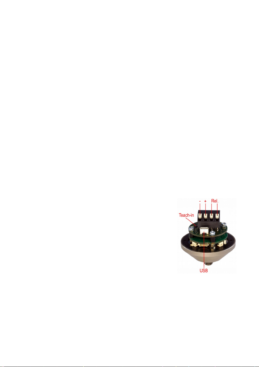
The parametrization is carried out with PC software via a common micro
USB cable. To connect the USB cable, unscrew the four socket head screws
and remove the lid. Inside you will see the USB connector (Figure 1).
Caution: If a USB cable is connected, the power will be supplied by the PC.
Make sure the power is never supplied via a USB cable and the connection
terminals simultaneously.
When connecting 3&(VS10 to a PC for the first time, you will be prompted to
install the driver. The driver file “MMF_VCP.zip” can be found on our
website:
Unzip and save both the enclosed files to a directory on the computer.
When Windows requests the location of the instrument driver, enter this directory. The instrument driver is signed and runs with Windows XP, Vista, 7, 8 and 10.
The driver installs a virtual COM Port on the PC and operates in CDC mode, thus enabling simple control
via the ASCII commands.
To setup the 3&(VS10 the PC-Software VS1x is available under the above link. Unzip the file vs1x.zip into a directory on your PC and then start setup.exe. The installation directories can be changed if needed. The program is a LabView application and for this reason installs several components of the LabView Run-Time en vironment from National Instruments.
Once installed, the program is located under Metra Radebeul in the start menu of your computer. (Figure 2).
Figure 1: Connections

Figure 2: Parameter Program
To establish a connection to 3&(VS10, press Search VS1x. The program searches COM-Ports 1 to 50 for the in strument. As soon as it has been found the status report VS1x connected appears and the instrument settings
are read.
In the row next to the COM port number you will find the non-editable data, model, version, serial number
and date of calibration. You can enter the device name yourself.
When entering the gain, this refers to the analogue pre-amplification before the analogue-to-digital converter
stage. The gain levels 1, 10 and 100-fold are available for selection as well as automatic gain switching. In
many cases automatic gain setting is most appropriate. It can, however, occasionally be disadvantageous if
single shock pulses are measured. If previously only low amplitudes had been recorded, it may occur that
short single impulses fail to trigger the alarm signal immediately, due to the switching of the gain. In such
cases a fixed gain should be set according to the maximum expected amplitude (fix).
Under Filter / Integrator there is a row of high and low pass filter combinations to choose from. Depending
on the area of application, you can monitor either acceleration without integration ( accel.) or the single integrated signal of velocity (veloc.). For vibrations below 1 kHz, for which the resulting energy is of relevance,
it is recommendable to monitor velocity, whereas for measurements involving higher frequencies and im pacts, acceleration is usually preferred.
Under Warning/Alarm you can find the limit value settings. Here your can select whether RMS values or
Peak values are to be monitored. Monitoring peak values can be advantageous for recording single events,
while RMS is relevant for trend monitoring, for example, in the field of machine condition monitoring. The
Alarm limit is entered in the unit of measurement (m/s² or mm/s). The instrument can give a warning signal
before it reaches the alarm limit. The warning threshold is entered as a percentage of the alarm limit.

The Teach-in factor, is the factor by which the vibration amplitude currently being measured is multiplied,
when by pressing the Teach-in (Figure 2) button, the alarm limit is automatically set. The Teach-in button is
accessible without opening the casing, you simply need to remove the screw cap. It is useful for setting the
alarm limit when there are no specific values available.
Under Switch Output you can determine the switching of the relay output. First of all, you can choose
whether the relay should open or close when the warning and alarm limit are exceeded. Power-on delay is
the duration of time between the power supply being connected and the relay being activated. It eliminates
false alarms during the settling process. Delay is the period of time which occurs between the alarm limit being exceeded and the relay switching. It helps prevent short shock pulses. Hold time is the time during which
the relay retains its switch status, after the vibration amplitude has dropped below the warning and alarm
limit again. It guarantees a minimum duration of time for the signaling of alarm events.
The programmed settings are immediately transferred to 3&(VS10. They can additionally be saved to a file
(Save). The file contains the ending .xml. By pressing Load you can reload the settings.
Set defaults restores 3&(VS10 to its factory settings.
Installation and Operation
Typical attachment points for 3&(VS10 are rigid components such as, cast iron cases, bearing houses, profiles
and foundations. Flexible components like thin sheet metal or plastic parts are unsuited. The 3&(VS10 can be
mounted in the vertical or horizontal direction, preferably be means of the supplied M8 screw. It is sufficient
to tighten the screw by hand, without using a tool.
The cable is lead-in through a waterproof cable gland. It can be used for multi-wire cables with diameters be tween 3.5 and 5.5 mm. The power supply (5 .. 30 V / <100 mA) is connected to the screw terminals 0V (negative pole) and +U (positive pole) (Figure 2). It is protected against reverse polarity.
3&(VS10 contains a PhotoMOS relay without mechanical contacts. The relay contacts are located on the two
right hand terminal pins. Please pay attention to the limit values for electrical load.
The alarm status of 3&(VS10 is indicated by the four LED's on the outer casing. If all LED's are lit green, there
is no warning or alarm. If two LED's are lit red and two green this indicates that the warning limit has been
exceeded. If all LED's are lit red, the alarm limit has been exceeded.

Technical Data
Monitoring Values Peak value and RMS value of vibration acceleration or vibration velocity
Measuring Range 0.1 to 1000 m/s² acceleration, velocity frequency dependent
High Pass Filter 0.1/2/5/10/20/50/100/200/500/1000 Hz (acceleration)
2/5/10/20/50 Hz (velocity)
Low Pass Filter 0.1/0.2/0.5/1/2/5/10 kHz (acceleration); 1 kHz (velocity)
Relay Output PhotoMOS relay; SPST; max. 60 V / 0.5 A (AC/DC);
Alarm Delay/ Hold Time 0 – 99 s / 0 – 9 s
USB Connection USB 2.0 full speed, CDC mode, micro USB socket
Power Supply Voltage 5 to 30 V DC; < 100 mA via screw terminals or USB supply voltage
Protection Grade IP67
Operating Temperature Range -40 – 80 °C
Weight 160 g
Dimensions 50 mm Ø, 52 mm height
Mounting M8 thread Pin; 8 mm length; coupling surface: Ø 25 mm
Open/close programmable, connection via screw terminals
 Loading...