

PCE Instruments PCE-VE 1500-22190, PCE-VE 1500-28200, PCE-VE 1500-60500, PCE-VE 1500-38200, PCE-VE 1500-38209 Users guide
...Page 1
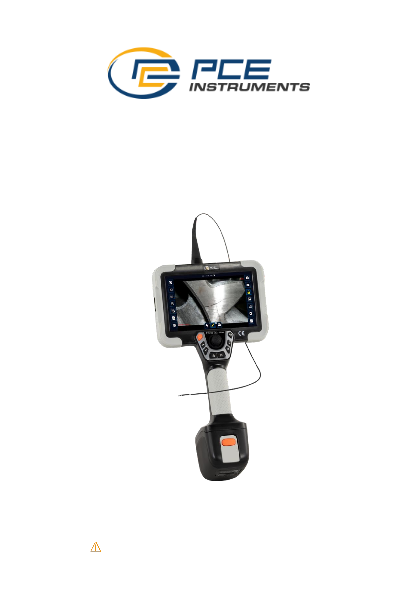
Product Manual
PCE-VE 1500 Series
Inspection technology for better future.
Please read the manual before using the equipment.
Page 2

Inspection technology for better future.
Declaration
The manual is only used for this series of products.
As this manual is used as product series manual, however, the configuration
and function of different models may be different, about the specific specification
and function, the technic requirements when you purchasing is the only
reference. For the manual amendment, we have no responsibility and obligation
to inform any company or individuals.
This manual is edited manually. Please understand if there is any error in
the content description.
Page 3

Inspection technology for better future.
1
Catalog
Instruction Before Use ............................................................................ 3
Main configuration ................................................................................... 3
Button and Port ........................................................................................ 4
Application ................................................................................................ 6
After-service. ............................................................................................. 6
After-service ............................................................................................. 6
Warning .................................................................................................... 6
1 Brief Introduction ................................................................................. 7
1.1 Parameters ........................................................................................ 7
2 Operation Steps .................................................................................... 8
2.1 Take out the instrument ................................................................... 8
2.2 Boot Preparation ............................................................................... 9
2.3 Operation ........................................................................................... 9
2.4 Probe articulation control ............................................................... 10
2.5 After use ........................................................................................... 10
3 Function Operational Specification ................................................ 11
3.1 Camera setting ................................................................................ 11
3.2 Picture-in-picture............................................................................. 11
Page 4

Inspection technology for better future.
2
3.3 Dual camera preview ..................................................................... 12
3.4 Image Rotation ................................................................................ 12
3.5 Photo/video preview ....................................................................... 13
3.6 Test Report ...................................................................................... 14
3.7 Snapshot .......................................................................................... 15
3.8 Video Record .................................................................................. 15
3.9 Image freezing ................................................................................ 15
3.10 Image Call ..................................................................................... 16
3.11 Measurement(Option) ............................................................ 16
3.12 Settings .......................................................................................... 18
3.13 Full Screen .................................................................................... 19
3.14 File storage path ........................................................................... 20
4 Solution to Common Problems ....................................................... 21
5 Product Assembly Diagram .............................................................. 22
Page 5
Inspection technology for better future.
3
Instruction Before Use
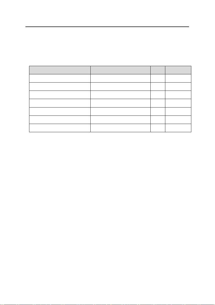
Main configuration
For the specific configuration, please refers to the packing list.
Name
Specs
Qty
Note
Case
580*345*230 mm
3
1
Videoscope
366mm*194mm*137mm
1
TF card
64G 1
Card reader
USB2.0 port
1 Rechargeable battery
7.4V,6400mAH
2
Option
Type-C cable
1m 1
Charger
USB-C charger(65W)
1
Page 6
Inspection technology for better future.
4
Button and Port
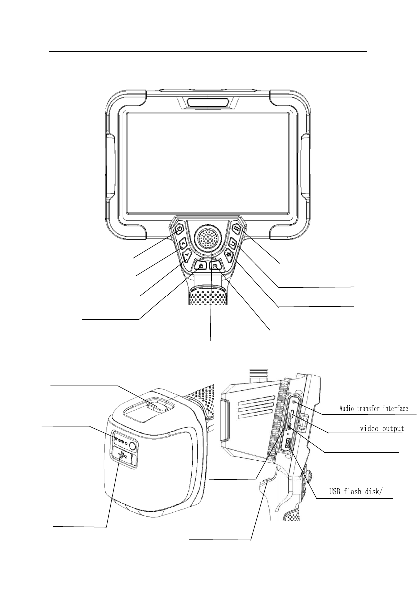
(4) Steering lock
(5) Menu
(2) Up
(6) Return
(3) Down
(9)Joystick
(1) On / off
(8) Steering speed control
(7) Brightness
USB interface
(15)Type-c
USB interface
(14)HDMI
(10)Power module removal button
(11)
Power capacity indicator
(with key)
(12)Type-C
charging port
(17)SD card slot
(13)
(18)Photo/video
Page 7

Inspection technology for better future.
5
(1) On/off: Long press this button for 3 seconds to boot; long press it for
3 seconds to shut down.
(2) Up: in menu setting mode, press this button to upward navigation.
(3) Down: in the preview interface, scroll down to enlarge 8 times.
(4) Steering lock:lock the steering angle of the joystick.
(5) Menu button: enter the system Settings, which mainly include storage
path setting, image calling, language setting, date/time setting,
watermark setting, etc.;
(6) Return: return to previous menu.
(7) Brightness control: control the light from 0-5 levels.
(8) Steering speed control:control the speed adjustment of the joystick
for the probe steering. There are two switching modes: fast and slow.
(9) Joystick:compatible with the steering adjustment and confirmation
keys of the probe, the steering angle can be adjusted up, down, left
and right, and short press down to confirm the operation.
(10) Battery module removal button:Used for disassembly and
replacement of battery module.
(11) Power indicator:display power capacity,dynamic running light mode
during charging, it does not light up after being fully charged. When
the power is insufficient, the last grid will flash.
(12) Type-C USB charging port: used for charging the battery module.
(13) Audio transfer interface: used for audio input of video recording
operation and audio output of video playback.
(14) HDMI: connect the monitor with display by HDMI cable, the image on
the monitor will be displayed synchronously on the display.
(15) Type-C USB port: Developers can upgrade and use it.
(16) USB flash disk / USB interface: used for copying, saving and
exporting local system files by USB flash disk and other devices.
(17) SD card slot: The maximum support for 128G memory.
(18) Photo/video: short press for taking photo, long press for taking video.
Page 8

Inspection technology for better future.
6
Application
This product can be used for defect or fault detection in aerospace,
automobile engine, automobile parts, military manufacturing, police safety,
power plant, special inspection and other fields. It is applicable to the detection
and analysis of industrial equipment or industrial site to ensure the safe
production and operation of equipment.
After-service
This product has not any spare parts which can be repair by users. Any
disassemble, refit or maintenance is not allowed. If damage and losses caused
by this, we do not assume any responsibility. The product maintenance is only
afforded by the authorized dealers and distributors.
Warning
warning
·Prohibit the use of this instrument to observe the body or the animal's body;
·Do not use the product to inspect equipment in action;
·Do not use or store the product on explosive, strong electromagnetic field
or with combustible gas, otherwise it may cause fire or explosion;
·Do not use the product to check objects with current carrying, so as to
avoid the occurrence of electric shock;
·Do not watch the LED light source at the end of the lens straightly, avoiding
the effect of strong light on the visual acuity;
·Never excessive bending, stretching, twisting, rolling cable, otherwise it
may cause cable disconnect, a fire or electric shock accident;
·If there is abnormal in the angle adjustment operation, stop the current
operation, and turn off. Then contact the supplier;
·Keep the insert tube away from any liquid, except water, salty water or oil;
·When finish using, please clean the front section of the instrument in time,
to prevent corrosion.
Page 9

Inspection technology for better future.
7
1 Brief Introduction
PCE-VE 1500 series endoscope is a hand-held electric three-dimensional
measurement endoscope. This product adopts full-color IPS full view LCD touch
screen, high-definition image sensor, high-sensitivity electric steering control
joystick and multi-layer tungsten-braided insertion tube. The whole machine is
easy to operate, durable and clear. It is mainly used in special inspection,
aviation, pipeline, pressure vessel, automobile manufacturing, electric power
and other industrial fields.
1.1 Parameters
Probe Diameter(mm)
Φ8/Φ6/Φ3.8/Φ2.8/Φ2.2/Φ1.8
Camera Pixels
1000000/300000
DOF
10-100mm/5-50mm
Probe material
Superwear-resisting alloy
FOV
120°
Viewing Direction
0° front view/90°side view
Illuminance
Max 50000Lx
Tube Material
tungsten-braided
Tube Length
1.5m/2m/3m(other lengths can be customized)
Protecting Device of
Durability
buffer protection device between the host and
wear-resistant tube
Articulation
360° all way
Bending Angle
Max 190°
Display
7-inch full-color full view IPS LCD touch screen
Display Resolution
1920*1200
Image/Video Format
JPG/MP4
Page 10

Inspection technology for better future.
8
Image Resolution
1280*720
Video Resolution
1280*720
Zoom function
Image 8X
Outer Case Material
anti-fall engineering alloy material
Memory
Built-in 16GB flash memory,external 64G SD
card (up to 128G)
Data Port
HDMI port、USB port、type-c port
Batteries
DC12V、detachable lithium batteries
Working Time
≥3
Battery Capacity
(7.4V,6400mAh)*2
Power Consumption
10W
Weight
≈ 2.4 kg(battery included)
Compatibility
The handle can be replaced; with a variety of
functional accessories
Standard Accuracy
0.1mm
Minimum Accuracy
0.01mm
Accuracy Rating
≥95%
Store Temperature
-23℃~63℃
Relative Humidity
Max: 92%, non-condensing
Host
Working Temperature
-15℃~50℃,when 0°C below, the display needs
preheating.
Camera
Working Temperature
-25℃~80℃ ,when 0°C below, please reduce
probe articulation.
2 Operation Steps
2.1 Take out the instrument
Open the instrument case, while taking out the instrument host, set aside
and pay close attention to the probe; avoid colliding the probe and scratching
probe lens.
Page 11

Inspection technology for better future.
9
2.2 Boot Preparation
Visually check whether the appearance of the videoscope is intact, connect
the handle to the host, straighten the insertion tube, and adjust the direction of
the probe to 0°.
2.3 Operation
It supports for 5 levels of brightness adjustment. Press the light control
button to suitable brightness. Slowly insert the tube to the inspected object. The
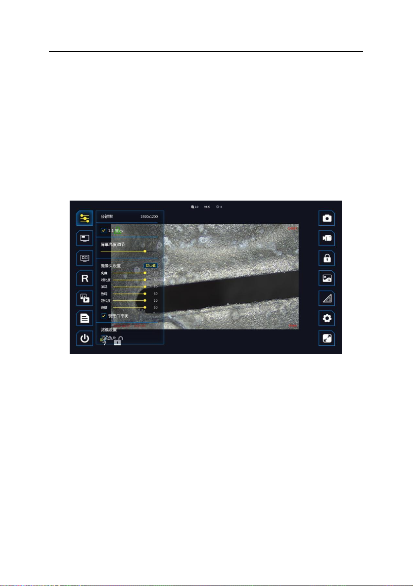
operation interface is as follows:
Below explains the functions of the floating window ICONS from top to bottom
and from left to right.
1. Camera setting, Set image parameters, proportions, special effects, etc.
2. Picture-in-picture, switch small window display function.
3. Dual camera preview, switch dual camera display.
4. Image rotation. The preview image rotates 90° clockwise each time on the
Date\time watermark
Distance watermark
1
2
3 4 5
6 7 8
9
10
11
12
13
Custom watermark
Camera watermark
14
15
16
Page 12

Inspection technology for better future.
10
interface.
5. Photo/video preview, view photos or videos, and access to system files.
6. Test report, in PDF format, packs a report of the selected photos.
7. Power off button, quick power off with one button.
8. Snapshot,Take pictures.
9. Video recording.
10. Image freezing. Freeze the image in the preview interface.
11. Call the image to complement the contrast image, and select the image that
needs to be displayed with a small window.
12.Measurement, 3D measurement function, providing a variety of
measurement methods.
13.Setting: Set the application, such as storage path setting, call image setting,
language setting, date \ time setting, watermark setting, etc.
14. Full screen, switch full screen display.
15. Steering speed: fast and slow mode, running posture represents fast mode,
and walking posture is slow mode.
Top of the screen:
1. Image zoom level display, can adjust from 0 to 8 levels by touch the screen.
2. Time display
3. Brightness indicator, 0~5 levels can be displayed.
2.4 Probe articulation control
According to the testing need, operate the joystick to control probe
articulation, in order to observe. The bending motion of the front probe is
controlled by rotating the joystick. During the operation, if the joystick suddenly
meets larger resistance, or there is any abnormity, please immediately stop
using. After adjust the joystick to the middle position, please remove the insert
tube carefully from the testing equipment.
2.5 After use
Before you remove the insert tube from the inspected object, please make
Page 13
Inspection technology for better future.
11
sure the probe is reset to be straight. If the product is damaged due to improper
operation, the user bears the loss. Turn off the power switch, put the instrument
into the portable case carefully, and put the tube into the case well.
3 Function Operational Specification
3.1 Camera setting
Click ICON 1 “camera Settings” to set various parameters of the camera.
You can view resolution, select the image scale and turn on the negative effects.
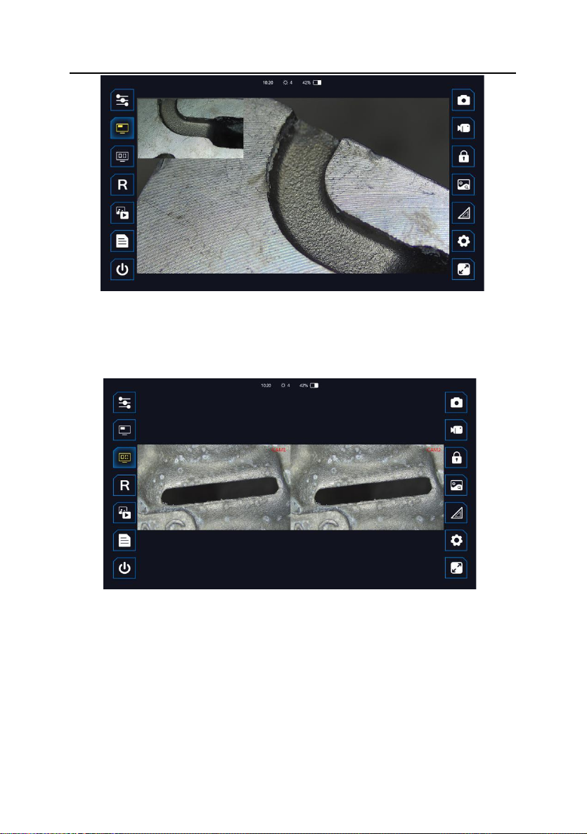
3.2 Picture-in-picture
Click ICON 2 "picture in picture", and the current live preview static picture
will appear in the upper left corner. You can click this static image to switch with
the real-time image. You can also select historical pictures for static comparison.
You need to "call pictures", see 3.11. After selecting pictures, you can use the
function‘picture-in-picture’.
Page 14
Inspection technology for better future.
12
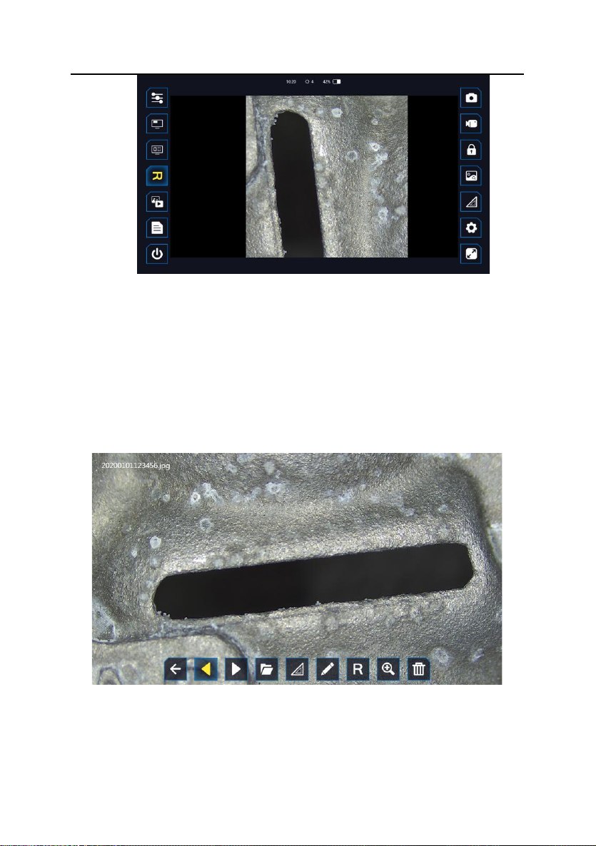
3.3 Dual camera preview
Click ICON 3 “dual camera preview” Dual cameras can be displayed on
the same screen.
3.4 Image Rotation
Click ICON 4 "Image Rotation". Rotate clockwise 90° each time, and with
mirror image display function.
Page 15
Inspection technology for better future.
13
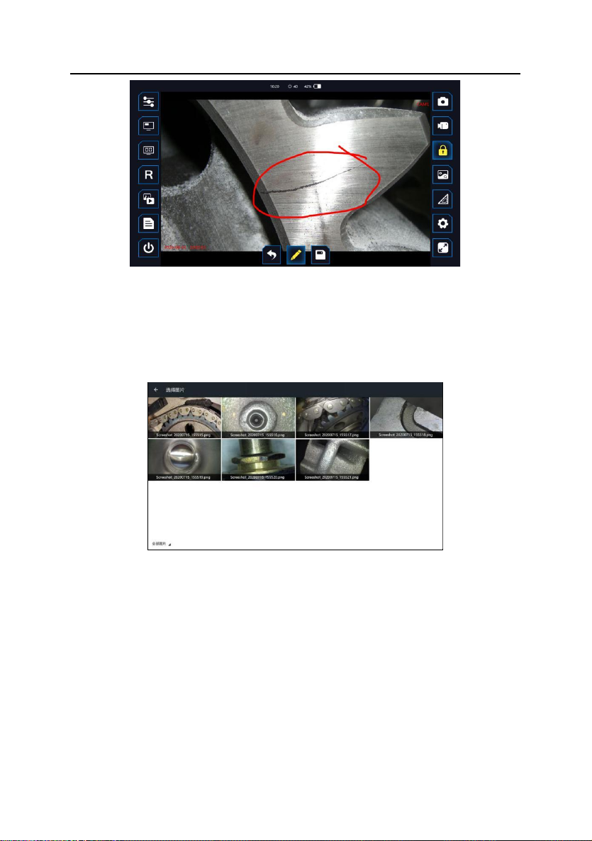
3.5 Photo/video preview
In the preview interface, click ICON 5 "Photo/Video Preview" to jump to the
file preview. You can switch files left and right, enter the file management system,
and delete files.
①Photos can be doodled, rotated and zoomed;
②Videos can be watched and paused;
③Click the folder icon to enter the system file interface.
Page 16

Inspection technology for better future.
14
3.6 Test Report
Select the image to automatically generate the PDF report.
After clicking the image, a small check mark will appear in the upper right
corner. Click the small check mark to complete the selection of the image and
the following interface will appear.
Page 17

Inspection technology for better future.
15
You can doodle and edit each image, or you can put edit text under each
image, and you can set the title of the file on the right.Once the Settings are
complete, click on the top right corner to create the test report.
3.7 Snapshot
Short press ICON 8 "Snapshot" to save "date \ time watermark", "Distance
watermark", "Custom watermark" and "Custom file name prefix", see 3.12;
The saved file is named in the form as follows:
3.8 Video Record
Short press ICON 9 "Video" to record video, and second short press to exit.
During recording, you can also short press to take photos. You can save "date \
time watermark", "Camera watermark", "Distance watermark" and "Custom
watermark" and "Custom file name prefix", see 3.12.
The saved file is named in the form as follows:
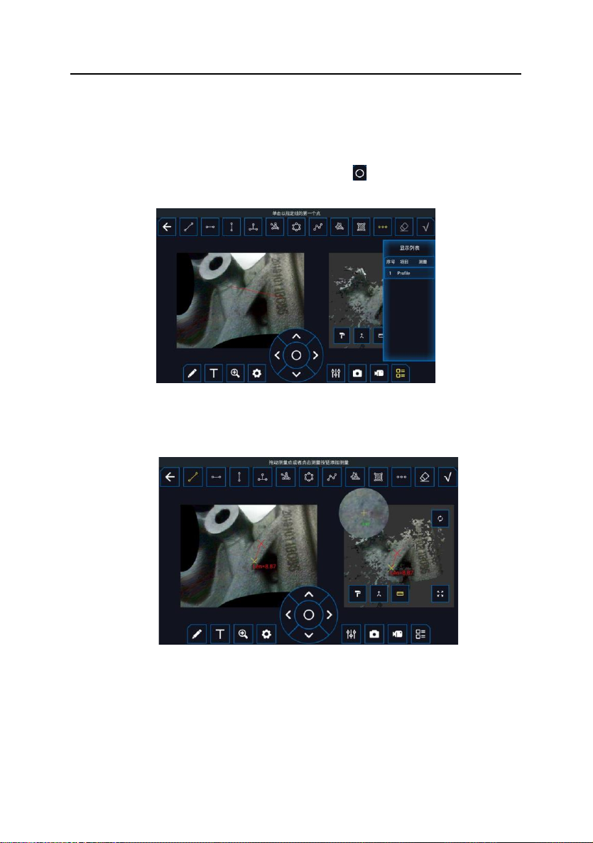
3.9 Image freezing
Click ICON 10 "Freeze", the image is frozen, and can be doodled and saved.
HMS
YMD
XXXX-20200215-
Prefix
HMS
YMD
XXXX-20200215-
Prefix
Page 18
Inspection technology for better future.
16
3.10 Image Call
Click ICON 11 "Freeze" "Image call" to select the image to be displayed in
"picture in Picture"
mode, see 3.2
3.11 Measurement(Option)
Click ICON 12 "measurement".to enter the measurement interface. The top
of the interface is the measurement method. From left to right: linear distance
from any point to point, linear distance from horizontal point to point, linear
distance from vertical point to point, point to linear distance, point to surface
distance, perimeter, polyline length, line to surface distance, area, section,
eraser, confirm.
At the bottom of the screen are the measuring tools and Settings.From left
to right are:doodle, add text, zoom, set constraint lines,navigation key, draw
Page 19
Inspection technology for better future.
17
settings, snapshot, video record, list.
The left area of the interface is plane measurement, and the right area is
3D cloud image area, which can be zoomed in and measured.
Select points on the left image first, use navigation keys, fine tune the
selection points up, down, left and right, and click " " key in the navigation keys
to cycle through the selection points.
Click the ruler key in the 3D cloud image area on the right to measure the
cloud image.Click the "confirm" button in the upper right corner to display the
measurement results and complete the measurement operation.
Click the section key in the upper tool area to view the section depth of the
area to be inspected on the left.
After entering the section tool, select any two points in the left area to form
a section depth view in the right area.
Page 20
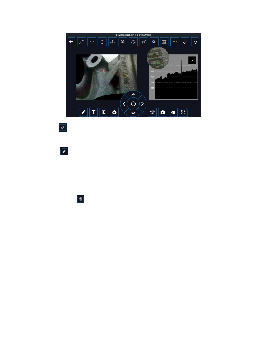
Inspection technology for better future.
18
Eraser : During the selection process, click the eraser button to return to
the top step.
Doodle : Click the doodle key to doodle on the left image and confirm in
the upper right corner.
Screen capture and recording: During the measurement process, you can
take any screen capture and recording to retain the measurement data and
operation process
Draw Settings : Adjust the measured line segment, font size and color.
List: The value after multiple measurements is displayed in the form of a list
on the right side. Click the serial number in the list, such as "1", and the "delete"
option pops up to delete the corresponding value and measurement point.
Note: Strong characteristics are needed to the selection point for
measurement.
3.12 Settings
Click ICON 13 "setting" to pop up the setting menu;
Page 21
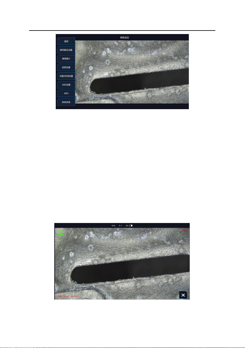
Inspection technology for better future.
19
Storage path Settings, set the storage path for photos and videos,see 3.14.
Image call, set the image to be called in picture-in-picture.
Language Settings, set system language, there are 8 languages optional.
Date/Time setting, set system date and time.
Watermark setting: Set the switch of "date \ time watermark, camera
watermark, distance watermark, custom watermark" ,"Custom file name prefix"
and draw seal style in the preview interface.
WiFi: WiFi is enabled, the system can be updated quickly
System information, view system version.
3.13 Full Screen
Display the image in full screen, hiding the left and right Settings floats.
Page 22
Inspection technology for better future.
20
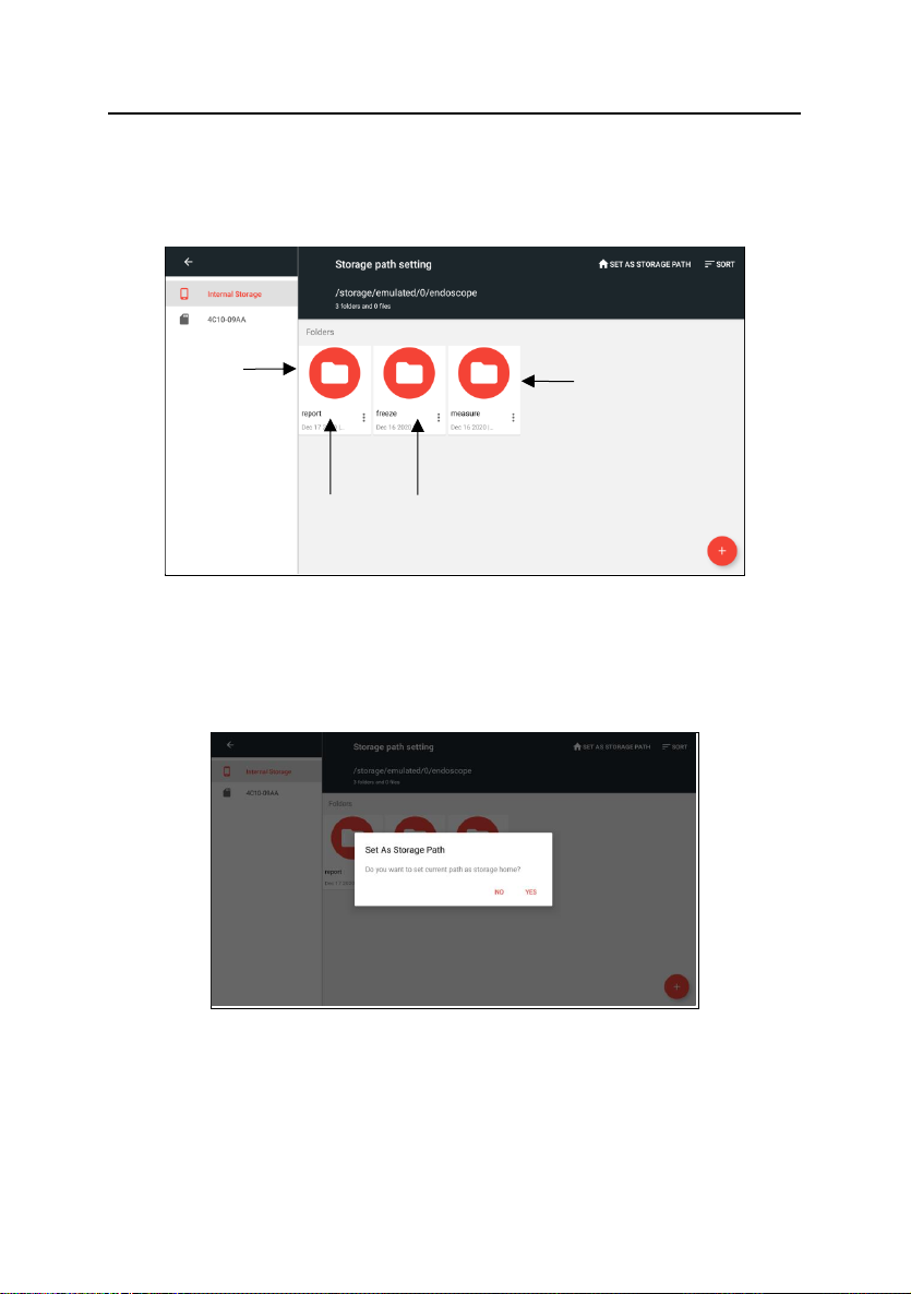
3.14 File storage path
Click ICON 13 "Settings" to enter the storage path Settings and enter the
file management interface.
Select the location you want to set as the default storage path, and click the
“small House” ICON in the upper right corner to set as the storage Path,then
pop up the dialog box to determine if you want to change the default storage
Path.
Note: When the memory card is unplugged, the device will automatically
restore internal memory as the default storage path. After the memory card is
inserted again, the memory card shall be set as the default storage path again.
Cache folder for
frozen image
Cache folder for
Measured image
Folder for test
report
Folder for doodle
image saved
Page 23

Inspection technology for better future.
21
4 Solution to Common Problems
Problem
Reason
Solution
Boot without
reaction
dead battery
charging
Auto shutdown
battery power
shortage
charge or change battery
Boot screen freezing
system boot failure
or battery power
shortage
remove the battery to re
install or charge, or forced
shutdown by triggered the
restart button
The image cannot be
recorded or found
the capacity of SD
card is not enough
Remove unwanted files
Image stuck and fail
to turn off
system stuck
forced shutdown by
triggered the restart button
Page 24
22
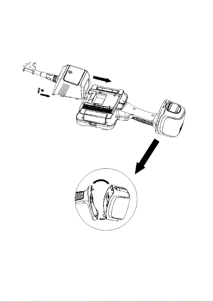
5 Product Assembly Diagram
Page 25

PCE Instruments contact information
Germany France Spain
PCE Deutschland GmbH PCE Instruments France EURL PCE Ibérica S.L.
Im Langel 26 23, rue de Strasbourg Calle Mula, 8
D-59872 Meschede 67250 Soultz-Sous-Forets 02500 Tobarra (Albacete)
Deutschland France España
Tel.: +49 (0) 2903 976 99 0 Téléphone: +33 (0) 972 3537 17 Tel. : +34 967 543 548
Fax: +49 (0) 2903 976 99 29 Numéro de fax: +33 (0) 972 3537 18 Fax: +34 967 543 542
[email protected] [email protected] [email protected]
www.pce-instruments.com/deutsch www.pce-instruments.com/french www.pce-instruments.com/espanol
United Kingdom Italy Turkey
PCE Instruments UK Ltd PCE Italia s.r.l. PCE Teknik Cihazları Ltd.Şti.
Trafford House Via Pesciatina 878 / B-Interno 6 Halkalı Merkez Mah.
Chester Rd, Old Trafford 55010 Loc. Gragnano Pehlivan Sok. No.6/C
Manchester M32 0RS Capannori (Lucca) 34303 Küçükçekmece - İstanbul
United Kingdom Italia Türkiye
Tel: +44 (0) 161 464902 0 Telefono: +39 0583 975 114 Tel: 0212 471 11 47
Fax: +44 (0) 161 464902 9 Fax: +39 0583 974 824 Faks: 0212 705 53 93
[email protected] [email protected] [email protected]
www.pce-instruments.com/english www.pce-instruments.com/italiano www.pce-instruments.com/turkish
The Netherlands United States of America Denmark
PCE Brookhuis B.V. PCE Americas Inc. PCE Instruments Denmark ApS
Institutenweg 15 1201 Jupiter Park Drive, Suite 8 Birk Centerpark 40
7521 PH Enschede Jupiter / Palm Beach 7400 Herning
Nederland 33458 FL Denmark
Telefoon: +31 (0)53 737 01 92 USA Tel.: +45 70 30 53 08
[email protected] Tel: +1 (561) 320-9162 [email protected]
www.pce-instruments.com/dutch Fax: +1 (561) 320-9176 www.pce-instruments.com/dansk
[email protected]
www.pce-instruments.com/us
 Loading...