


Vibration Data Logger
Model : PCE-VDR 10
OPERATION MANUAL
PCE Americas Inc.
711 Commerce Way
Suite 8
Jupiter
FL-33458
USA
From outside US: +1
Tel: (561) 320-9162
Fax: (561) 320-9176
info@pce-americas.com
www.pce-instruments.com/english
www.pce-instruments.com
PCE Instruments UK Ltd.
Units 12/13
Southpoint Business Park
Ensign way
Hampshire / Southampton
United Kingdom, SO31 4RF
From outside UK: +44
Tel: (0) 2380 98703 0
Fax: (0) 2380 98703 9
info@industrial-needs.com
Your purchase of this
VIBRATION DATA
RECORDER marks a
step forward for you
into the eld of
precision measurement.
Although this Meter is a
complex and delicate
instrument, its durable
structure will allow
many years of use if
proper operating
techniques are
developed. Please read
the following
instructions carefully
and always keep this
manual within easy
reach.
OPERATION

TABLE OF CONTENTS
1. FEATURES...............................................................................
................................
1
2. SPECIFICATIONS.................................................................................
....................
2
3. FRONT PANEL DESCRIPTION....................................................
.............................
5
4. MEASURING PROCEDURE................................................
.......................
6
5. DATALOGGER......................................................................................
.....................
9
5-1 Preparation before execute datalogger function...............................................................................
9
5-2 Datalogger...........................................................................
....................................
11
5-3 Check time information.........................................................................................
12
5-4 SD Card Data structure.................................................................................12
6. Saving data from the SD card to the computer..............................................................13
7. ADVAN
CED SETTING......................................................................................................14
7-1 Set clock time ..........................................................................................................15
7-2 Set sampling time...........................................................................................15
7-3 Set Auto Power OFF ..........................................................................................16
7-4 Set b
eeper sound ON/OFF...........................................................................16
7-5 Set SD card Decimal character.............................................. ...... ....................17
7-6 Set UNIT ............................................................................................ 18
8. POWER SUPPLY from DC ADAPTER..................................................................19
9. BATTERY REPLACEMENT..........................................................................19
10. SYSTEM RESET...............................................................................................19
11. RS232 PC serial interface.................................................................................20

1. FEATURES
* Applications for industrial vibration monitoring :
All industrial machinery vibrates. The level of vibration is
a useful guide to machine condition. Poor balance,
misalignment & looseness of the structure will cause the
vibration level increase, it is a sure sign that the
maintenance is needed.
* Frequency range 10 Hz – 1kHz, sensitivity relative meet
IOS 2954.
* Profressional vibration meter supply with vibration sensor
& magnetic base, full set.
* Metric & Imperial display unit.
* Acceleration, Velocity measurement.
* RMS, Max hold , Peak value measurement.
* Max. Hold reset button, Zero button.
* Wide frequency range.
* Data hold button to freeze the desired reading.
* Memory function to record maximum and minimum
reading with recall.
* Separate vibration probe with magnetic base, easy operation.
* Real time SD memory card Datalogger, it Built-in Clock
And Calendar,real time data recorder, sampling time set
From 5 second to 3600 seconds.
* Innovation and easy operation, computer is not need
to setup extra software, after execute datalogger, just
take away the SD card from the meter and plug in the
SD card into the computer, it can down load the all the
measured value with the time information(
year/month/date/hour/minute/second) to the Excel
directly, then user can make the further data or graphic
analysis by themselves.
* SD card capacity : 1 GB to 16 GB.
1

* LCD with green light backlight, easy reading.
* Can default auto power off or manual power off.
* Data hold, record max. and min. reading.
* Microcomputer circuit, high accuracy.
* Power by UM4/AAA( 1.5V ) x 6 batteries or DC 9V adapter.
* RS232/USB PC COMPUTER interface.
2. SPECIFICATIONS
2-1 General Specifications
Circuit Cust
om one-chip of microprocessor LSI
circuit.
Display LCD size : 60 mm x 50 mm
Measurement Acceleration,Velocity,Displacement
Memory Card SD memory card. 1 GB to 16 GB.
Datalogger 5/10/30/60/120/300/600/1800/3600 seconds
Sampling Time
Data error no.
≦ 0.1 % no. of total saved data typically.
Advanced
* Set clock time ( Year/Month/Date, Hour/Minute/
setting
Second )
* Set sa
mpling time
* Set Auto Power OFF
* Set beeper sound ON/OFF
* Set SD card Decimal character
* SD memory card Format
* Set UNIT
Update Time Approx. 1 second if measuring data
of Display
is changed.
2

Data Output RS 232/USB PC computer interface.
* Connect the optional RS232 cable
UPCB-02 will get the RS232 plug.
* Connect the optional USB cable
USB-01 will get the USB plug.
Operating
0 to 50 ℃
.
Temperature
Operating Less than 85% R.H.
Humidity
Power Supply * DC 9V adapter input. ( AC/DC power
* Meter & adapter is included ).
probe
Power Supply * Alkaline or heavy duty DC 1.5 V battery
* Clock backup ( UM4, AAA ) x 6 PCs, or equivalent.
probe
battery
Weight 199 g/0.44 LB.
Dimension 132 x 80 x 32 mm
( 5.2 x 3.1 x 1.3 inch )
Accessories *
Instruction manual..............................
1 pcs.
Included *
Vibration Sensor(VB-81A)..................
1 pcs.
*
SKT-AS385................................................
1 pcs.
Optional
* SD Card ( 2 GB )
Accessories
* 2 wires pressure transmitter, TR-PS2W
* USB cable,
USB-01.
* RS232 cable, UPCB-02.
* Data Acquisition software, SW-U801-WIN.
* Excel Data Acquisition software, SW-E802.
* AC-AP9VA (AC to DC 9V adapter)
3
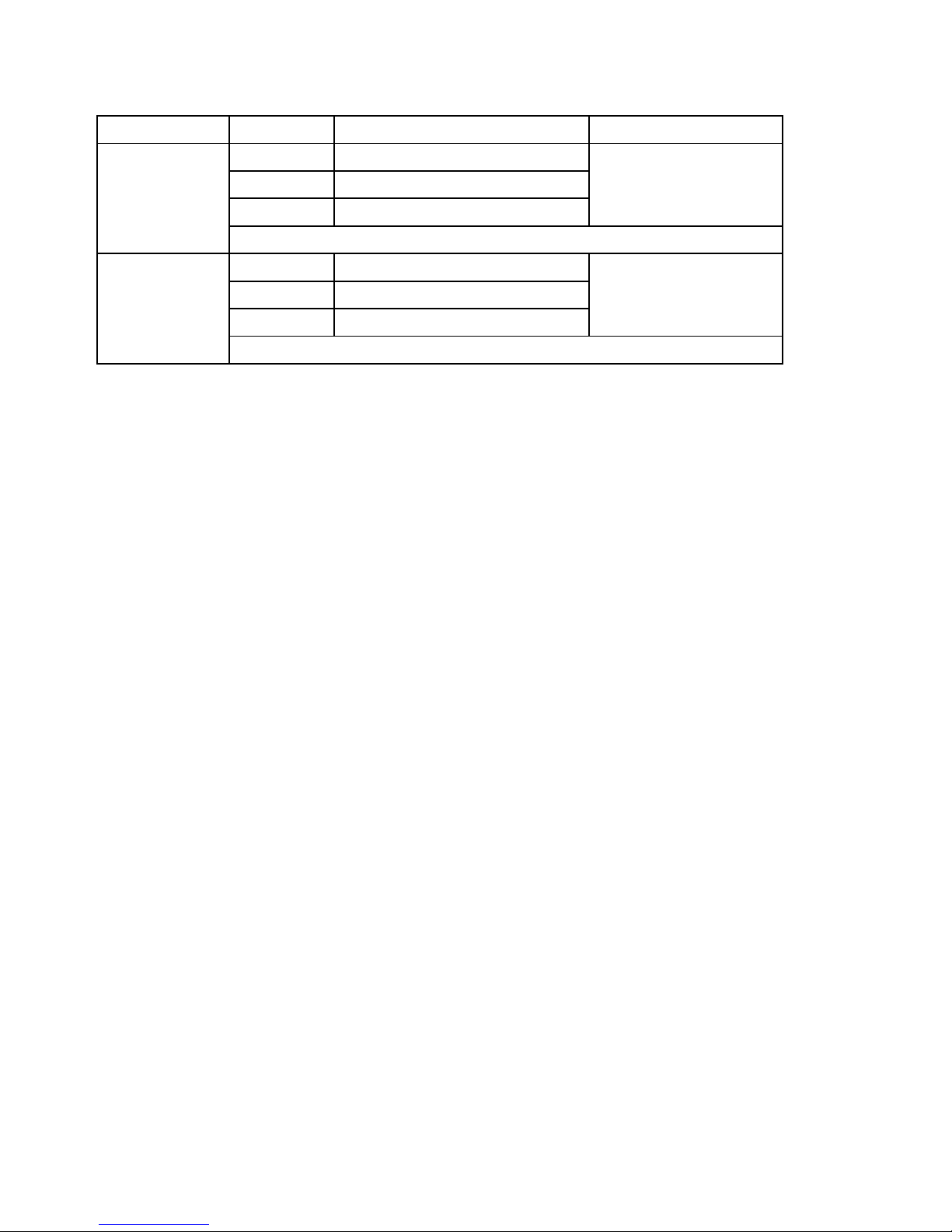
2-2 Electrical Specifications (23±5 ℃℃℃℃ )
Function Unit Range and Resolution Accuracy
Acceleration m/s2 0.5 to 199.9 m/s2
g 0.05 to 20.39 G ± ( 5%rdg + 2 d )
ft/s2 2 to 656 ft/s2 @ 80 and 160Hz
Calibration Point: 50 m/S^2 ( 160 Hz )
Velocity mm/s 0.5 to 199.9 mm/s
cm/s 0.05 to 19.99 cm/s ± ( 5%rdg + 2 d )
inch/s 0.02 to 7.87 inch/s @ 80 and 160Hz
Calibration Point: 50 mm/s ( 160 Hz )
Above specification tests under the environment RF Field Strength
less than 3 V/M & frequency less than 30 MHz only and 23°C ±0.5°C
4
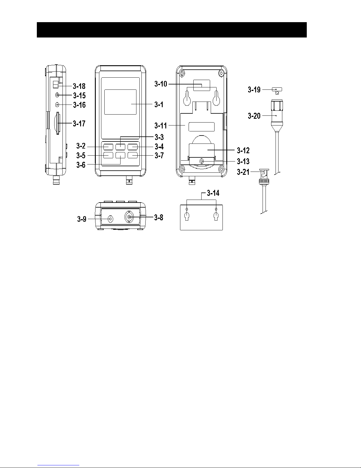
3. FRONT PANEL DESCRIPTION
Fig. 1
3-1 Display 3-12 Batt
ery cover/Battery compartment
3-2 Power button ( Backlight button ) 3-13 Screw of the battery cover
3-3 ▲ Button ( Unit Button )
3-14 Hanging unit ( with sticker )
3-4 REC Button ( HOLD Button ) 3-15 Reset Button
3-5 SET Button ( Time Button ) 3-16 RS-232 Output Terminal
3-6 ▼ Button ( Function Button )
3-17 SD card socket
3-7 Logger button ( Enter button ) 3-18 4-20 mA Output Terminal
3-8 Vibration Sensor input BNC socket 3-19 Reset Button
3-9 DC 9V power adapter input socket 3-20 Vibration Sensor
3-10 Hanging holes 3-21 Vibration Sensor BNC
3-11 Stand

5
4. MEASURING PROCEDURE
1) Power supply installation :
* The met
er's power supply should install the batteries
and connect " AC to DC adapter " together.
* The batteries are the power of " Clock ".
Batteries
Install the batteries into the battery compartment :
* Loose the " Screw of the battery cover " ( 3-13, Fig. 1 )
and take away the " Battery Cover " ( 3-12, Fig. 1 ) from
the meter.
* Replace with DC 1.5 V battery ( UM4/AAA, Alkaline/Heavy
duty type ) x 6 PCs, and reinstate the cover.
* Make sure the battery cover is secured after changing
the battery.
AC to DC adapter
* The " AC to DC adapter " is the standard accessory.
* Plug the output plug of " AC to DC adapter " into
the " DC 9V power adapter input socket " ( 3-9, Fig. 1 )
2) Vibration Sensor
Connect the vibration pickup to the cable supplied
Make sure it is firmly attached. Connect the cable
to the meter by attaching it to the "BNC connector( 3-8, Fig. 1 )
on the Bottom of the meter.If the surface to be tested is magnetic,
attach the magnetic base to the vibration pickup and attach the
pickup to a flat surface.If the surface to be tested is not magnetic,
hold the pickup against the surface. Do not hold the cable while
making measurements.

3) Vibration unit
The currently selected unit of measure is shown on the
meter’s LCD. To change the unit of measure, press and hold
the ▲ Button " Unit Button ( 3-3, Fig. 1 )" until the desired unit
of measure appears and then release the button.
if want change metric or imperial please refer chapter 7-7 (page 18 ).
4) Function Selection
The currently selected function is shown on the meter’s
LCD. To change the function, press and hold the button.
"FUNCTION button( 3-6, Fig. 1 )" until the desired function
appears, then release the FUNCTION .
The available functions are:
RMS: Typical selection for Acceleration and Velocity
PEAK: Displays the peak value of the vibration
MAX HOLD: Displays and holds the max value measured
MAX HOLD Reset:
Press and hold the ▲ and ▼ buttons for > 3 seconds to clear the
Max. Hold reading.

7
5) Data Hold:
To freeze a displayed reading on the LCD, momentarily press
the"HOLD button ( 3-4, Fig. 1 )" (the HOLD icon will appear
above the reading). To exit HOLD, press the HOLD button again.
6) ZERO Adjustment
The ZERO function is used to remove any small offset caused
by temperature changes or other environmental changes.
The zero will only work for a display of 10 or less digits.
1. Connect the vibration sensor to the meter
2. Set the measurement function to Acceleration
3. Make sure the sensor is motionless and not subject to
any vibrations.
4. Press and Hold the ▼ and ▲buttons for 3 seconds and the
meter will show zero .
7) REC ( Record):
For a given measurement session, this meter can record the
highest (MAX) and the lowest (MIN) readings for later recall.
1. Press the REC button momentarily to access this mode
of operation (REC icon appears)
2. The meter is now recording the MAX and MIN readings.
3. Press the REC button again to view the current
MAX readings (MAX icon appears). The readings on the
display are now the highest readings encountered since
the REC icon wasswitched on (when the MAX-MIN button
was first pressed).
4. Press the REC button again to view the current MIN
readings (MIN icon appears). The readings on the display
are now the lowest readings encountered since the REC icon
was switched on (when the REC button was first pressed).
5. To exit the MAX-MIN mode, press and hold the REC
button for 3 seconds. The meter will beep, the REC-MAX-MIN
icons will switch off, the MAX-MIN memory will clear,
and the meter will return to the normal operating mode.

8
8) Time check :
Press the "Time button ( 3-5, Fig. 1 )" once,display will be show
Year/Month/Date, Hour/Minute/ Second and samling time
information.
9) 4-20 mA output :
connect anather mA meter in to the viberation data recorder
(3-18 Fig. 4-20 mA Output Terminal) socket,At this time the
viberation data recorder will be output 4 - 20 mA analog signal
( display show 0 = 4.00mA out, show full scale = 20.00 mA out).
5. DATALOGGER
5-1 Preparation before execute datalogger function
Insert the SD card
Prepare
a " SD memory card " ( 1 GB to 16 GB, optional ),
insert the SD card into the " SD card socket " ( 3-17, Fig. 1)
with the correct direction exactly.
*
It recommend use memory card's capacity is ≦≦≦≦ 4 GB.
* It recommend strongly, do not use memory cards
that
h
ave been formatted by other meter or by
other installation ( such as camera... ). Reformat
the memory card with your meter.
* If the SD memory card exist the trouble during
format by the meter, use the Computer to
reformat again can fix the problem.

c. Time setting
If the meter is used at first time, it should to adjust the
clock time exactly, please refer chapter 7-1 ( page 15 ).
d. Decimal format setting
The numerical data structure of SD card is
default used the " . " as the decimal, for
example "20.6" "1000.53" . But in certain
countries ( Europe ...) is used the " , " as the
decimal point, for example " 20, 6 " ,
"1000,53". Under such situation, it should
change the Decimal character at first, details
of setting the Decimal point, refer to Chapter
7-5, page 17
e. 3 Information of LCD display
* If the Display show :
It means that the SD card exist the problem
CHANGE
or the SD card memory is full, it should
SD CARD
change SD memory card.
* If the
Display show :
It means that the battery is low voltage.
LOW
BATTER
10

* If the Display show :
It means that the SD card is not plugged
SD CARD
into the meter.
EMPTY
5-2 Datalogger
a. Start the datalogger
Press the " Logger button ( 3-7, Fig. 1 ) > 2 seconds
continuou
sly, until the Display show the indicator "
DATALOGGER ", release the " Logger Button " ( 3-7, Fig.
1 ), then the measuring data along the time information
will be saved into the memory circuit.
Remark :
*
How to set the sampling time, refer to Chapter 7-2,
page 15.
*
How to set the beeper sound is enable, refer to
Chapter
7-4, page 16.
b. Finish the Datalogger
During execute the Datalogger function ( Display show the
" Datalogger " indicator ), press the " Logger button " ( 3-7,
Fig. 1 ) > 2 seconds continuously, until the Display
indicator " DATALOGGER " is disappeared, release the
" Logger Button " will finish the Datalogger function.
Before take away the SD card from the
meter, it should execute the
procedures of " Finish the Datalogger ",
( It should wait for the Display counter to count
down to
zero value. )
otherwise some existing recent save
data may
loss.
11

5-3 Check time information
Press " Time button " ( 3-5, Fig. 1 ) > 2 seconds
continuously, the LCD display will present the time
information of Year/Month/Date, Hour/Minute/Second and
the sampling value.
5-4 SD Card Data structure
1) When the SD card is used into the meter, the SD card
When the first time, the SD card is used into the meter,
the SD card will generate a folder :
VBC01
2)
If the first time to execute the Datalogger, under the
route VBC01\, will generate a new file name
VBC01001.XLS.
After exist the Datalogger, then execute again, the data
will save to the VBC01001.XLS until Data column reach
to 30,000 columns, then will generate a new file, for
example VBC01002.XLS
3)
Under the folder VBC01\, if the total files more
than 99 files, will generate anew route, such as
VBC02\ ........
4)
The file's route structure :
VBC01\
VBC01001.XLS
VBC01002.XLS
.....................
VBC01099.XLS
VBC02\
VBC02001.XLS
VBC02002.XLS
.....................
VBC02099.XLS
VBCXX\
.....................
Remark :
XX : Max. value is 10.
12
6. Saving data from the SD card
to the computer ( EXCEL software )
1) After execute the Data Logger function, take away the
SD card
out from the " SD card socket " ( 3-17, Fig. 1 ).
2) Plug in the SD card into the Computer's SD card slot
( if your computer build in this installation ) or
insert the SD card into the " SD card adapter ". then
connect the " SD card adapter " into the computer.
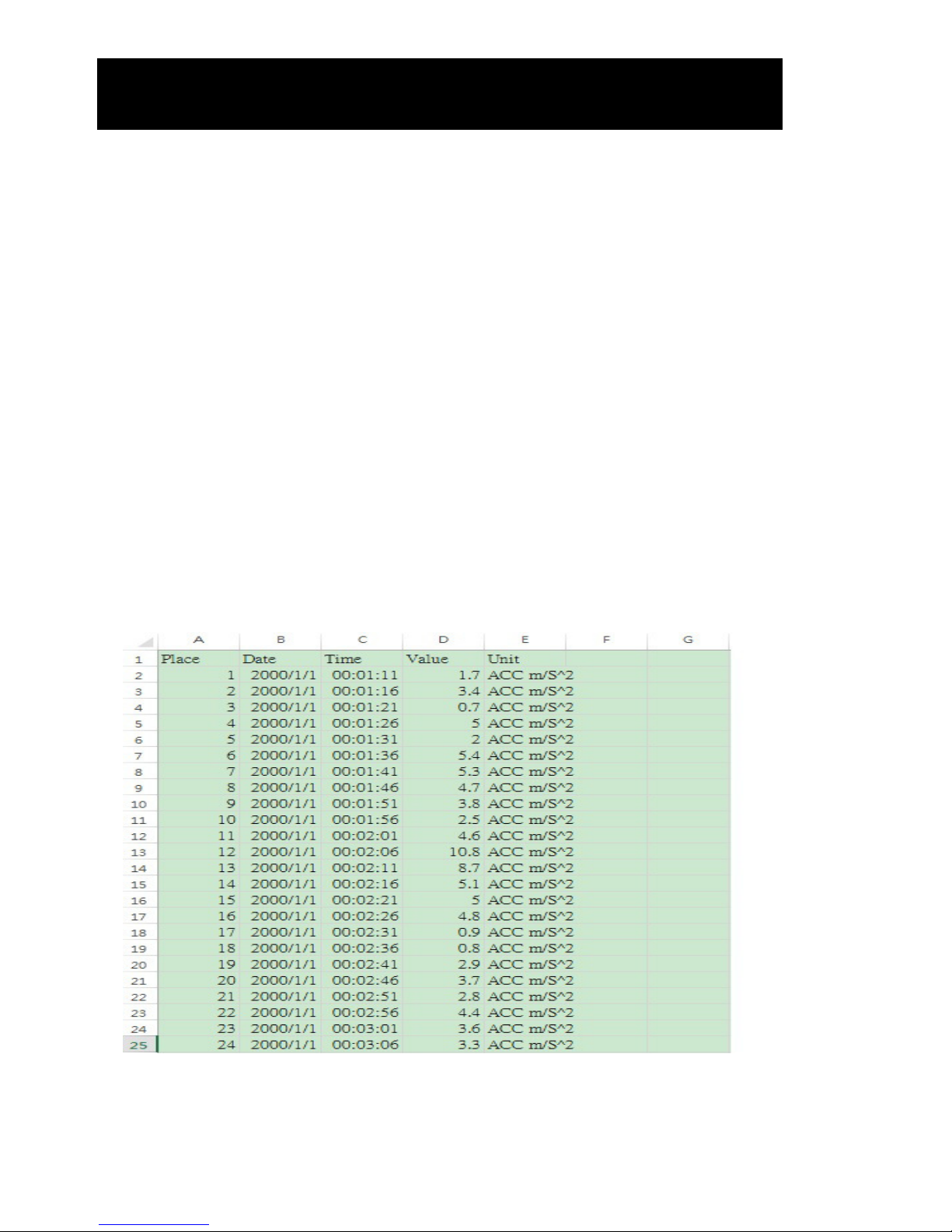
3) Power ON the computer and run the " EXCEL software ".
Down load the saving data file ( for example the file
name : VBC01001.XLS, VBC01002.XLS ) from the SD
card to the computer. The saving data will present into
the EXCEL software screen ( for example as following
EXCEL data screens ) , then user can use those EXCEL
data to make the further Data or Graphic analysis
usefully.
EXCEL data screen ( for example )
13
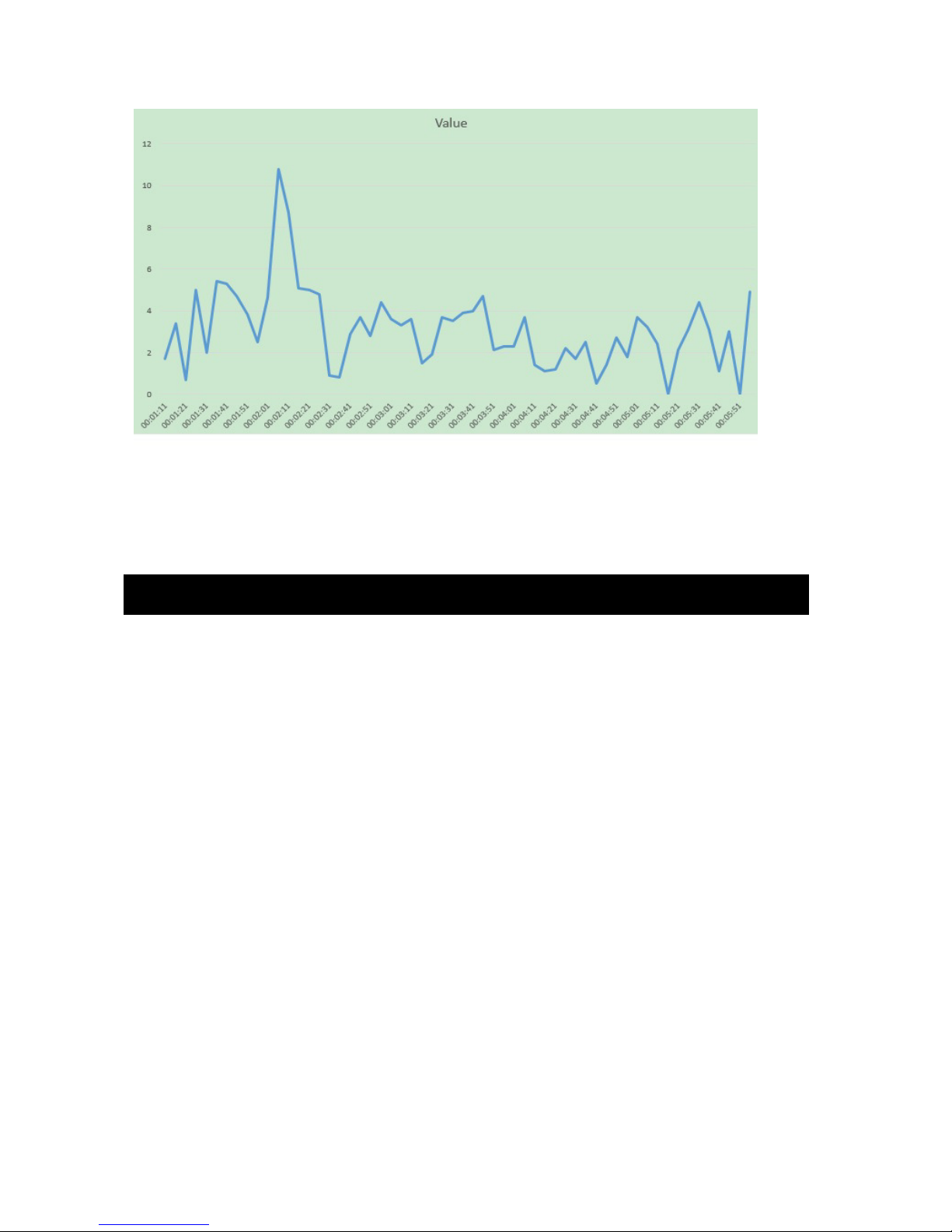
EXCEL graphic screen ( for example )
7. ADVANCED SETTING
Under do not execute the Datalogger function, press the
"
SET butto
n " ( 3-5, Fig. 1 ) > 2 seconds continuously will
enter the " Setting " mode., then release the " SET button ".
Following press the " SET button " (3-5, Fig. 1 ) once a
while in sequence to select the seven main function, the
display will show :
SET DATE......
Set clock time ( Year/Month/Date, Hour/Minute/
Second )
SP-T.......
Set sampling time
POFF........
Set Power Auto OFF
bEEP........
Set beeper sound ON/OFF
DEC........
Set SD card Decimal character USA/EURO
UNIT……..
METRIC / IMPERIAL
14

Remark :
During execute the " Setting " function, if within
5 seconds , do not press any buttons further, the
LCD Display will return to normal screen.
7-1 Set clock time ( Year/Month/Date,
Hour/Minute/ Second )
When the Display show " SET DATE "
1)
Use the " ▲ Button " ( 3-3, Fig. 1 ) or " ▼ Button "
( 3-6, Fig. 1 ) to adjust the value ( Setting start from
Year value ). After the desired value is set, press the
" Enter button " ( 3-7, Fig. 1 ) once will going to
next value adjustment ( for example, first setting
value is Year then next to adjust Month, Date, Hour,
Minute, Second value ).
Remark :
The adjusted unit will be flashed.
2) After set all the time value ( Year, Month, Date, Hour,
Minute, Second ), press the " SET button " ( 3-5, Fig.
1 ) once will save the time value, then the screen will
jump to Sampling time " setting screen ( Chapter 7-2 ).
Remark :
After the time value is setting, the internal clock will
run precisely even Power off if the battery is under
normal condition ( No low battery power ).
7-2 Set sampling time
When the Display show " SP-T "
1)
Use the " ▲ Button " ( 3-3, Fig. 1 ) or " ▼ Button "
( 3-6, Fig. 1 ) to adjust the sampling value :
15

5 seconds, 10 seconds, 30 seconds, 60 seconds,120 seconds
, 300 seconds, 600 seconds,1800seconds,3600 seconds.
After the desired value is set, press the " Enter Button "
( 3-7, Fig. 1 ) to save the adjusting value with default.
7-3 SET POFF ON/OFF
When the Display show " POFF "
1)
Use the " ▲ Button " ( 3-3, Fig. 1 ) or " ▼ Button "
( 3-6, Fig. 1 ) to select the text to " yES " or " no ".
YES - Meter's will be Auto power off .
NO - Meter's Auto power off Will be disable.
2) After select the upper text to " YES " or " NO ", press the
" Enter Button " ( 3-7, Fig. 1 ) will save the setting
function with default.
7-4 Set beeper sound ON/OFF
When the Display show " BEEP "
1)
Use the " ▲ Button " ( 3-3, Fig. 1 ) or " ▼ Button "
( 3-6, Fig. 1 ) to select the text to " YES " or "NO ".
YES - Meter's beep sound will be ON with default.
NO - Meter's beep sound will be OFF with default.
2) After select the upper text to " YES " or " NO ", press the
" Enter Button " ( 3-7, Fig. 1 ) will save the setting
function with default.
16

7-5 Decimal point of SD card setting
When the Display show " DEC "
The numerical data structure of SD card is used the " . "
as the decimal with default, for example "20.6"
"1000.53" . But in certain countries ( Europe ...) is
used the " , " as the decimal point, for example " 20,6 "
"1000,53". Under such situation, it should change the
Decimal character at rst.
1)
Use the "
Button " ( 3-3, Fig. 1 ) or " Button "
( 3-6, Fig. 1 ) to select the upper text to " USA " or
" EURO ".
USA - Use " . " as the Decimal point with default.
EURO - Use " , " as the Decimal point with default.
2) After select the text to " USA " or " EURO ",
press the " Enter Button " ( 3-7, Fig. 1 ) will save the
setting function with default.
17

7-6 Set UNIT
When the Display show "UNIT METRIC "
1)
Use the " ▲ Button " ( 3-3, Fig. 1 ) or " ▼ Button "
( 3-6, Fig. 1 ) to select the upper Display text to METRIC
or IMPERIAL
2) press the " Enter Button " ( 3-7,
Fig. 1 ) will save the setting METRIC or IMPERIAL with default.
18

8. POWER SUPPLY from DC
ADAPTER
The meter also can supply the power supply from the DC
9V Power Ad
apter. Insert the plug of Power Adapter into
" DC 9V Power Adapter Input Socket " ( 3-9, Fig. 1 ).
9. BATTERY REPLACEMENT
1) When the left corner of LCD display show " ", it
is necess
ary to replace the battery. However, in-spec.
measurement may still be made for several hours after
low battery indicator appears before the instrument
become inaccurate.
2) Loose the " Screw of the battery cover " ( 3-13, Fig. 1 )
and take away the " Battery Cover " ( 3-12 Fig. 1 ) from
the instrument and remove the battery.
3) Replace with DC 1.5 V battery ( UM4/AAA,
Alkaline/heavy duty ) x 6 PCs, and reinstate the cover.
4) Make sure the battery cover is secured after changing
the battery.
10. SYSTEM RESET
If the meter happen the troubles such as :
CPU syste
m is hold ( for example, the key button can
not be operated... ).
Then make the system RESET will fix the problem.
The system RESET procedures will be either following
method :
During the power on, use a pin to press the " Reset
Button " ( 3-15, Fig. 1 ) once a while will reset the
circuit system.
19

11. RS232 PC SERIAL INTERFACE
The instrument has RS232 PC serial interface via a 3.5 mm
terminal ( 3
-16, Fig. 1 ) .
The
data output is a 16 digit stream which can be
utilized for user's specific application.
Remark:
* When power use AC/DC adapter , the RS-232 signal will output
A RS232 lead with the following connection will be
required to link the instrument with the PC serial port.
Meter PC
(9W 'D" Connector)
Center Pin............................................
Pin 4
(3.5 mm jack plug)
Ground/shield...........................................
Pin 2
2.2 K
resistor
Pin 5
The 16 digits data stream will be displayed in the
following format :
D15 D14 D13 D12 D11 D10 D9 D8 D7 D6 D5 D4 D3 D2 D1 D0
20

Each digit indicates the following status :
D0 End Word
D1 & D8 Display reading, D1 = LSD, D8 = MSD
For example :
If the display reading is 1234, then D8 to
D1 is : 00001234
D9 Decimal Point(DP), position from right to the
left
0 = No DP, 1= 1 DP, 2 = 2 DP, 3 = 3 DP
D10 Polarity
0 = Positive 1 = Negative
D11 & D12 Annunciator for Display
m / s 2 = 92 g = 57 mm / s =
93
cm / s = 95 ft / s 2 = 97 inch / s = 98
D13 When send the up display data = 1
When sen
d the middle display data = 2
D14 4
D15 Start Word
RS232 FORMAT : 9600, N, 8, 1
Baud rate 9600
Parity No parity
Data bit no. 8 Data bits
Stop bit 1 Stop bit
21
 Loading...