

© PCE Instruments
PCE-VDL 16I + PCE-VDL 24I Vibration Analyzer
Bedienungsanleitung
User Manual
User manuals in various languages (français,
italiano, español, português, nederlands, türk, polski,
русский, 中文) can be found by using our
product search on: www.pce-instruments.com
Letzte Änderung / last change: 10 December 2018
V1.1
English
Deutsch

© PCE Instruments
Deutsch
Inhaltsverzeichnis
1 Sicherheitsinformationen ..................................................................... 1
2 Spezifikationen ...................................................................................... 1
2.1 Technische Spezifikationen .............................................................................................. 1
2.2 Spezifikationen der verschiedenen integrierten Sensoren ................................................ 2
2.3 Spezifikation der Akku Laufzeit......................................................................................... 3
2.4 Spezifikation der Messdauer (2.500.000 Messwerte) ....................................................... 3
2.5 Lieferumfang ................................ ................................................................ .................... 3
2.6 Zubehör ........................................................................................................................... 3
3 Systembeschreibung ............................................................................ 4
3.1 Einleitung ......................................................................................................................... 4
3.2 Gerät ................................................................................................................................ 4
3.3 MicroSD-Karte im Datenlogger ......................................................................................... 5
4 Vorbereitung .......................................................................................... 6
4.1 Montage mit der optionalen Adapterplatte PCE-VDL MNT ............................................... 6
4.2 Montage ohne Adapterplatte ............................................................................................ 6
4.3 SD-Karte .......................................................................................................................... 6
5 Betrieb .................................................................................................... 7
5.1 Verbinden von PC und Datenlogger ................................................................................. 7
5.2 Systemvoraussetzungen für PC-Software ........................................................................ 7
5.3 Softwareinstallation .......................................................................................................... 7
5.4 Beschreibung der Softwarebenutzeroberfläche ................................................................ 8
5.5 Bedeutung der Symbole in der Symbolleiste der PC-Software ......................................... 8
6 Bedienung ............................................................................................ 10
6.1 Die erste Benutzung der Software ...................................................................................10
6.2 Verbindung zum "PCE-VDL X" herstellen ........................................................................11
6.3 Verbindung zum " PCE-VDL X" trennen ..........................................................................11
6.4 Ausschalten des Datenloggers ................................................................ ........................11
6.5 Informationen zu einem verbundenen Datenlogger abrufen ............................................12
6.6 Testen der Sensoren .......................................................................................................13
6.7 2 Punkt Kalibrierung der Sensoren Temperatur und Feuchte ..........................................14

© PCE Instruments
6.8 Starten einer Messung ....................................................................................................15
6.9 Übertragen und Laden von Messreihen ........................................................................... 17
6.10 Löschen von Messreihen.................................................................................................18
6.11 Die Auswertung von Messreihen .....................................................................................19
6.11.1 Tabellarische Ansicht ............................................................................................20
6.11.2 Statistiken .............................................................................................................21
6.11.3 Grafische Ansicht ..................................................................................................22
6.11.4 Gemischte Ansicht (grafisch plus tabellarisch).......................................................25
7 Mögliche Fehlermeldungen ............................................................... 26
8 Garantie ................................................................................................ 27
9 Entsorgung .......................................................................................... 27

© PCE Instruments
English
Contents
1 Safety notes ......................................................................................... 28
2 Specifications ...................................................................................... 28
2.1 Technical specifications ..................................................................................................28
2.2 Specifications of the different integrated sensors .............................................................29
2.3 Specification of the battery life .........................................................................................29
2.4 Specification of the measuring time (2,500,000 readings)................................................31
2.5 Delivery contents .............................................................................................................31
2.6 Optional accessories .......................................................................................................31
3 System description ............................................................................. 32
3.1 Introduction .....................................................................................................................32
3.2 Device .............................................................................................................................32
3.3 MicroSD card in the data logger ................................ ................................ ......................33
4 Getting started ..................................................................................... 34
4.1 Attachment of the optional adaptor plate PCE-VDL MNT.................................................34
4.2 Attachment without using the adaptor plate .....................................................................34
4.3 SD card ...........................................................................................................................34
5 Operation ............................................................................................. 35
5.1 Connecting the data logger to your PC ............................................................................35
5.2 System requirements for PC software .............................................................................35
5.3 Software installation ........................................................................................................35
5.4 Description of the user interface in the software ..............................................................36
5.5 Meaning of the individual icons in the toolbar of the PC software ....................................36
6 Operation ............................................................................................. 38
6.1 The first use of the software ................................................................ ............................38
6.2 Connect to the "PCE-VDL X" ...........................................................................................39
6.3 Disconnect from the " PCE-VDL X" .................................................................................39
6.4 Switch off the data logger ................................................................................................39
6.5 Retrieve information on connected data logger ................................................................40
6.6 Test the sensors ..............................................................................................................41
6.7 2-point calibration of the temperature and humidity sensors ............................................42

© PCE Instruments
6.8 Start a measurement .......................................................................................................43
6.9 Transfer and load series of measurements ......................................................................45
6.10 Delete series of measurements .......................................................................................46
6.11 Evaluate series of measurements ...................................................................................47
6.11.1 Tabular view ..........................................................................................................48
6.11.2 Statistics ...............................................................................................................49
6.11.3 Graphical view.......................................................................................................50
6.11.4 Mixed view (graphical plus tabular)........................................................................53
7 Possible error messages ................................................................... 54
8 Warranty ............................................................................................... 54
9 Disposal ............................................................................................... 54

© PCE Instruments
1
Deutsch
1 Sicherheitsinformationen
Bitte lesen Sie dieses Benutzer-Handbuch sorgfältig und vollständig, bevor Sie den Datenlogger
zum ersten Mal in Betrieb nehmen. Die Benutzung darf nur durch sorgfältig geschultes Personal
erfolgen. Schäden, die durch Nichtbeachtung der Hinweise in der Bedienungsanleitung
entstehen, entbehren jeder Haftung.
• Der Datenlogger darf nur in der in dieser Bedienungsanleitung beschriebenen Art und
Weise verwendet werden. Wird er anderweitig eingesetzt, kann es zu gefährlichen
Situationen kommen.
• Das Öffnen des Gerätegehäuses darf nur von Fachpersonal der PCE Deutschland
GmbH vorgenommen werden.
• Benutzen Sie den Datenlogger nie mit nassen Händen.
• Es dürfen keine technischen Veränderungen am Gerät vorgenommen werden.
• Der Datenlogger sollte nur mit einem Tuch gereinigt werden. Verwenden Sie keine
Scheuermittel oder lösungsmittelhaltige Reinigungsmittel.
• Der Datenlogger darf nur mit dem von der PCE Deutschland GmbH angebotenen
Zubehör oder gleichwertigem Ersatz verwendet werden.
• Überprüfen Sie das Gehäuse des Messgerätes vor jedem Einsatz auf sichtbare
Beschädigungen. Sollte eine sichtbare Beschädigung auftreten, darf das Gerät nicht
eingesetzt werden.
• Das Messgerät darf nicht in einer explosionsfähigen Atmosphäre eingesetzt werden.
• Der in den Spezifikationen angegebene Messbereich darf unter keinen Umständen
überschritten werden.
• Wenn die Sicherheitshinweise nicht beachtet werden, kann es zur Beschädigung des
Gerätes und zu Verletzungen des Bedieners kommen.
Für Druckfehler und inhaltliche Irrtümer in dieser Anleitung übernehmen wir keine Haftung.
Wir weisen ausdrücklich auf unsere allgemeinen Gewährleistungsbedingungen hin, die Sie in
unseren Allgemeinen Geschäftsbedingungen finden. Bei Fragen kontaktieren Sie bitte die PCE
Deutschland GmbH. Die Kontaktdaten finden Sie am Ende dieser Anleitung.
2 Spezifikationen
2.1 Technische Spezifikationen
Spezifikation
Erläuterung
Speicherkapazität
2,5 Millionen Messwerte pro Messung
3,2 Milliarden Messwerte mit beigelegter 32 GB microSDSpeicherkarte
IP-Schutzart
IP40
Spannungsversorgung
Integrierter Li-Ion Akku 3,7 V / 500 mAh
Akkuladung über USB-Anschluss
Schnittstelle
Micro USB
Betriebsbedingungen
Temperatur: -20 ... +65 °C
Lagerbedingungen
(ideal für Akku)
Temperatur: 5 ... 45 °C
Luftfeuchtigkeit: 10 ... 95 % r. H. nicht kondensierend
Gewicht
ca. 60 g
Abmessungen
86,8 x 44,1 x 22,2 mm

© PCE Instruments
2
Deutsch
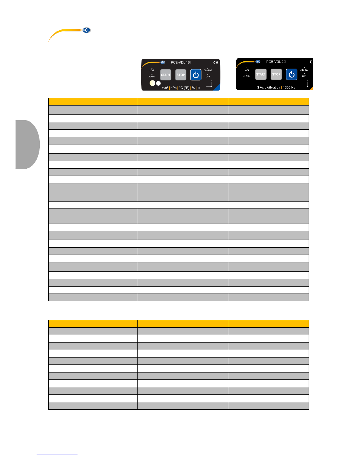
2.2 Spezifikationen der verschiedenen integrierten Sensoren
Spezifikation
PCE-VDL 16I (5 Sensoren)
PCE-VDL 24I (1 Sensor)
Temperatur
Messbereich
-20 … 65 °C
-
Genauigkeit
±0,2 °C*
-
Auflösung
0,01 °C
-
Max. Abtastrate
1 Hz
-
Luftfeuchtigkeit
Messbereich
0 … 100 % RH
-
Genauigkeit
±1,8 % RH
-
Auflösung
0,04 % RH
-
Max. Abtastrate
1 Hz
-
Luftdruck
Messbereich
10 … 2000 mbar
-
Genauigkeit
±2 mbar (750 … 1100 mbar);
sonst ±4 mbar
Auflösung
0,02 mbar
-
Licht
Messbereich
0,045 … 188.000 Lux
-
Auflösung
0,045 Lux
-
Max. Abtastrate
1 Hz
-
3 Achsen
Beschleunigung
Messbereich
±16 g
±16 g
Genauigkeit
±0,24 g
±0,24 g
Auflösung
0,00390625 g
0,00390625 g
Max. Abtastrate
800 Hz
1600 Hz
*nicht während des Ladevorgangs

© PCE Instruments
3
Deutsch
2.3 Spezifikation der Akku Laufzeit
Abtastrate [Hz]
Laufzeit PCE-VDL 16I
Laufzeit PCE-VDL 24I
1 Hz
2d 06h 21min
1d 14h 59min
3 Hz
2d 06h 12min
1d 14h 54min
6 Hz
2d 05h 57min
1d 14h 48min
12 Hz
2d 05h 28min
1d 14h 34min
25 Hz
2d 04h 27min
1d 14h 06min
50 Hz
2d 02h 33min
1d 13h 13min
100 Hz
1d 23h 03min
1d 11h 32min
200 Hz
1d 17h 05min
1d 08h 32min
400 Hz
1d 08h 39min
1d 03h 48min
800 Hz
1d 00h 39min
0d 22h 09min
1600 Hz
0d 15h 46min
Die Spezifikation der Akku Laufzeit gelten für einen neuen und vollständig geladenen Akku und
mit der im Lieferumfang enthaltenen microSD-Karte vom Typ: TS32GUSD300S-A.
2.4 Spezifikation der Messdauer (2.500.000 Messwerte)
Abtastrate [Hz]
Laufzeit PCE-VDL 16I
Laufzeit PCE-VDL 24I
1 Hz
5d 18h 53min
28d 22h 26min
3 Hz
4d 03h 12min
9d 15h 28min
6 Hz
2d 05h 58min
4d 19h 44min
12 Hz
1d 19h 24min
2d 09h 52min
25 Hz
0d 23h 56min
1d 03h 46min
50 Hz
0d 12h 51min
0d 13h 53min
100 Hz
0d 06h 40min
0d 06h 56min
200 Hz
0d 03h 24min
0d 03h 28min
400 Hz
0d 01h 43min
0d 01h 44min
800 Hz
0d 00h 51min
0d 00h 52min
1600 Hz
0d 00h 26min
Die angegebenen Laufzeiten und Abtastraten gelten nur in Verbindung mit der im Lieferumfang
enthaltenen microSD-Karte vom Typ: TS32GUSD300S-A.
2.5 Lieferumfang
1x Datenlogger PCE-VDL 16l oder PCE-VDL 24I
1x Datenkabel USB A – Micro USB
1x 32 GB microSD Karte
1x Schiebeelement für SD-Karte
1x USB Stick mit PC Software und Bedienungsanleitung
2.6 Zubehör
Artikelnummer
Artikelbeschreibung
PCE-VDL MNT
Adapterplatte mit Magnetbefestigungen,
Schrauben- und Langlochaufnahmen
CAL-VDL 16I
Kalibrierzertifikat für PCE VDL 16I
CAL-VDL 24I
Kalibrierzertifikat für PCE VDL 24I
© PCE Instruments
4
Deutsch
3 Systembeschreibung
3.1 Einleitung
Datenlogger registrieren in einem bestimmten Rhythmus wichtige Parameter bei der Beurteilung
von mechanischen und dynamischen Belastungen. Typische Einsatzgebiete sind u. A.
Transportüberwachungen, Fehlerdiagnose und Belastungstests.
3.2 Gerät
Anschlüsse
Tastenfunktionen
1
Anschluss für Datenkabel: Micro USB
7
Ein- und Ausschalter
2
Speicherkarteneinschub
8
STOP: Beendung der Messung
9
START: Beginn einer Messung
LED Anzeigen
Sensorpositionen: nur PCE-VDL 16I
3
LOG: Statusanzeige / Log-Intervall
10
Feuchtesensor
4
ALARM: rot bei Grenzwertüberschreitung
11
Lichtsensor
5
CHARGE: grün im Lademodus
6
USB: grün bei PC Verbindung
© PCE Instruments
5
Deutsch
3.3 MicroSD-Karte im Datenlogger
Stecken Sie die microSD-Karte mit zwei Fingern in die Speicherkartenaufnahme und schieben
Sie diese anschließend mit dem Schiebeelement bis die SD Karte einrastet.
Um die microSD-Karte aus dem Datenlogger zu entnehmen, führen Sie das Schiebelement in die
Speicherkartenaufnahme ein. Die Speicherkarte löst sich aus ihrer Halterung und schiebt sich so
aus dem Gehäuse, dass sie anschließend herausgenommen werden kann.
Zum Auslesen der Daten stecken Sie die microSD-Speicherkarte zusammen mit dem SD Karten
Adapter in einen PC.

© PCE Instruments
6
Deutsch
4 Vorbereitung
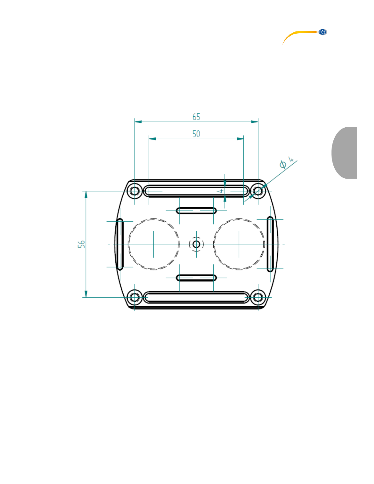
4.1 Montage mit der optionalen Adapterplatte PCE-VDL MNT
Der Datenlogger kann auf einer Adapterplatte befestigt und mit Hilfe der Bohrungen oder an den
parallelen Langlöchern am Messobjekt fixiert werden. Rückseitig ist die Adapterplatte
magnetisch, so dass eine Befestigung auch auf magnetischen Untergründen problemlos möglich
ist. Die Verwendung der Adapterplatte eignet sich insbesondere bei der Aufzeichnung von
Schwingungen, Vibrationen und Schockereignissen, da zwecks genauer Messergebnisse eine
möglichst steife Verbindung zwischen dem Messobjekt und dem Datenlogger bestehen sollte.
4.2 Montage ohne Adapterplatte
Ohne die optionale Adapterplatte kann der Datenlogger an einer beliebigen Position am
Messobjekt positioniert werden. Für Messgrößen wie Temperatur, Feuchte oder Luftdruck und
Licht reicht in der Regel ein einfaches Ablegen oder Festklemmen des Datenloggers an der
Messstelle aus. Auch ein Aufhängen am Schutzbügel des Datenloggers ist möglich.
4.3 SD-Karte
Bei Nutzung einer SD-Karte, welche nicht im Lieferumfang enthalten ist, muss die SD-Karte vor
der Verwendung formatiert werden (FAT32 Dateisystem). Für hohe Abtastraten des
Beschleunigungssensors (800 Hz beim PCE-VDL 16I und 1600 Hz beim PCE-VDL 24I) ist
mindestens eine Class 10 (U1) microSD-Karte notwendig. Die Spezifikation der Akku Laufzeit
gilt nur mit der im Lieferumfang enthalten microSD-Karte.
© PCE Instruments
7
Deutsch
5 Betrieb
5.1 Verbinden von PC und Datenlogger
Bevor die verschiedenen Sensoreinstellungen in der Software festgelegt werden können,
verbinden Sie das Datenkabel mit dem PC und dem Micro USB Anschluss am Datenlogger. Die
LEDs CHARGE und USB leuchten. Ist der Akku geladen, schaltet sich die CHARGE LED
automatisch wieder aus.
Mit der Taste schalten Sie den Datenlogger ein und aus.
5.2 Systemvoraussetzungen für PC-Software
• Betriebssystem ab Windows XP SP3
• USB-Port (2.0 oder höher).
• Ein installiertes .NET-Framework 4.0
• Eine Mindestauflösung von 800x600 Pixel
• Optional: ein Drucker
• Prozessor mit 1 GHz
• 4 GB RAM Arbeitsspeicher
• Einen Datenlogger ("PCE-VDL 16I" oder "PCE-VDL 24I")
Empfohlen: Betriebssystem (64 Bit) ab Windows 7 aufwärts
Mindestens 8 GB RAM Arbeitsspeicher
5.3 Softwareinstallation
Bitte führen Sie die "Setup PCE-VDL X.exe" aus und folgen Sie den Anweisungen des Setups.
© PCE Instruments
8
Deutsch
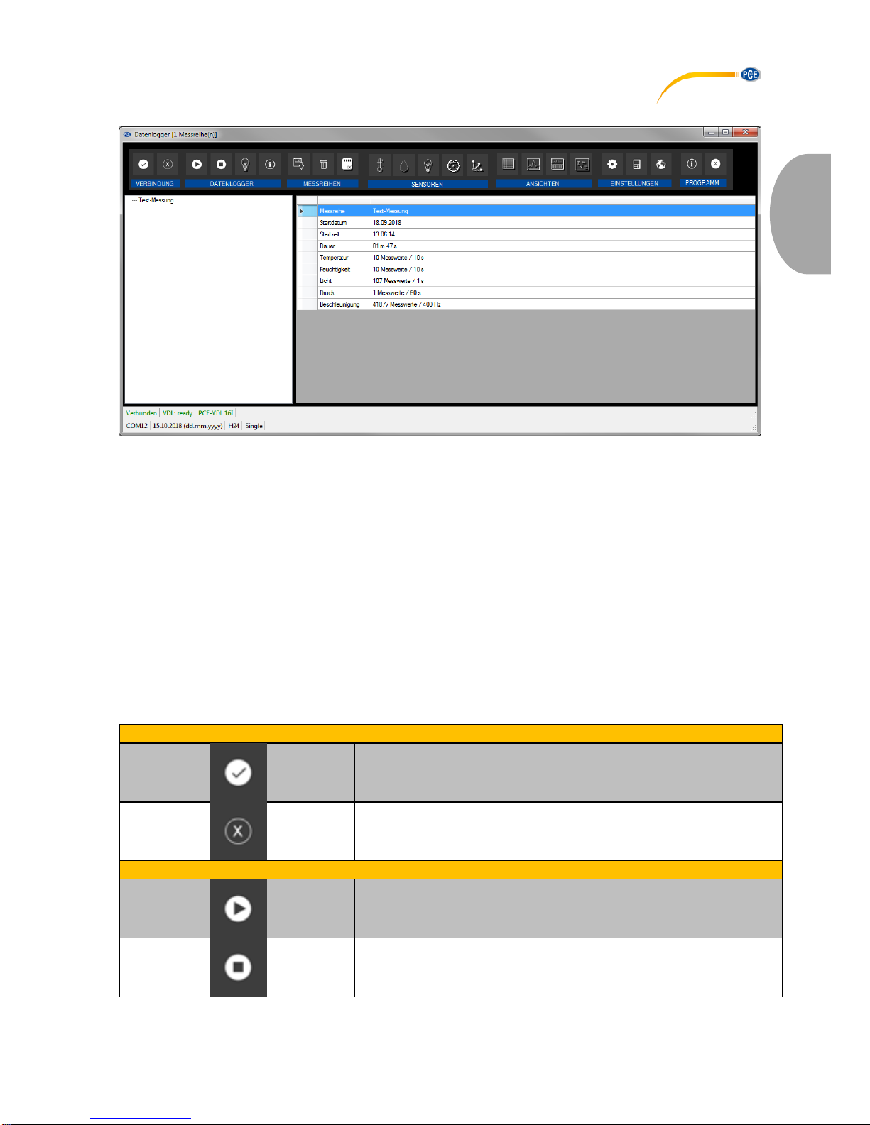
5.4 Beschreibung der Softwarebenutzeroberfläche
Das Hauptfenster setzt sich aus mehreren Bereichen zusammen:
Unterhalb der Titelleiste befindet sich eine Symbolleiste, deren Symbole funktional gruppiert sind.
Unter dieser Symbolleiste befindet sich im linken Teil des Fensters eine Auflistung von
Messreihen.
Der rechte Teil des Fensters enthält eine kurze Übersicht einer ausgewählten Messreihe.
Am unteren Rand des Hauptfensters befinden sich zwei Statusleisten mit wichtigen Informationen
direkt übereinander.
Die untere der beiden zeigt die statischen Einstellungen des Programms, die über einen
Einstellungs-Dialog festgelegt werden können.
Die obere Statusleiste zeigt die dynamischen Einstellungen bzw. Daten des "PCE-VDL X", die
direkt von dem verbundenen Gerät abgerufen werden. Dies betrifft auch die Information, ob
aktuell eine Messung läuft oder auch, um welche Bauart es sich bei dem angeschlossenen
Datenlogger handelt ("PCE-VDL 16I" oder "PCE-VDL 24I").
5.5 Bedeutung der Symbole in der Symbolleiste der PC-Software
Gruppe "Verbindung"
Verbindung mit dem "PCE-VDL X" herstellen
Verbindung mit dem " PCE-VDL X" trennen
Gruppe "Datenlogger"
Eine Messung starten
Eine Messung beenden

© PCE Instruments
9
Deutsch
Sensoren testen
Informationen zu einem angeschlossenen Datenlogger
Gruppe „Messreihen“
Eine Messreihe vom Datenlogger oder aus dem Cache
laden
Messreihe aus dem Programmspeicher entfernen
Messreihe endgültig löschen
Gruppe „Sensoren“
Temperatursensor
Feuchtigkeitssensor
Lichtsensor
Drucksensor
Beschleunigungssensor
Gruppe „Ansichten“
Tabellarische Ansicht
Grafische Ansicht
Grafische und tabellarische Ansicht
Statistiken

© PCE Instruments
10
Deutsch
Gruppe "Einstellungen"
Den Einstellungs-Dialog für statische Gerätedaten aufrufen
Den Einstellungs-Dialog für dynamische Gerätedaten
aufrufen
Auswahl einer vom Programm unterstützten Sprache
Gruppe "Programm"
Einen Informations-Dialog anzeigen
Das Programm beenden
6 Bedienung
6.1 Die erste Benutzung der Software
Bevor der Datenlogger "PCE-VDL X" mit der Software zusammenarbeiten kann, muss einmalig
der zugewiesene COM-Port in der Software eingestellt werden. Dieser kann mit Hilfe des
"Einstellungs-Dialogs" festgelegt werden.
Zusätzlich zu den Verbindungsdaten können hier noch weitere Einstellungen zur Darstellung von
Ansichten zu Messreihen sowie zum Datums- und Zeitformat vorgenommen werden.

© PCE Instruments
11
Deutsch
"Nur Fenster der aktuellen Messreihe darstellen" blendet Ansichten aus, die nicht zur aktuell
ausgewählten Messreihe gehören.
Ist dieser Modus aktiv, so wird in der unteren Statuszeile des Hauptfensters der Text "Single"
dargestellt.
Bei Auswahl von "Sämtliche Fenster aller Messreihen darstellen" hingegen werden alle Ansichten
aller geladenen Messreihen gezeigt.
In diesem Fall erscheint in der unteren Statuszeile des Hauptfensters der Text "Multiple“.
Über die Schaltfläche "Ändern..." kann die Standardgröße der Fenster für alle Ansichten
festgelegt werden.
6.2 Verbindung zum "PCE-VDL X" herstellen
Nachdem die gewünschten Einstellungen vorgenommen wurden, schließen Sie das Fenster
Einstellungen mit einem Klick auf die "Übernehmen"-Schaltfläche.
Bevor Sie weiter im Softwareprogramm arbeiten, schalten Sie den Datenlogger ein.
Drücken Sie die Taste .
Die LOG LED beginnt im Rhythmus von ca. 10 Sekunden zu blinken.
Jetzt klicken Sie im Hauptfenster der Symbolleiste auf die Schaltfläche in der Gruppe
"Verbindung".
Konnte die Verbindung erfolgreich hergestellt werden, so wird in der Statusleiste für die
dynamischen Daten z. B. Folgendes in grüner Farbe dargestellt.
Die gefüllte Schaltfläche zeigt an, dass die Verbindung aktiviert ist.
6.3 Verbindung zum " PCE-VDL X" trennen
Mit einem Klick auf das betreffende Symbol kann eine aktive Verbindung zum
"PCE-VDL X" wieder getrennt werden. Die gefüllte Schaltfläche zeigt an, dass die
Verbindung getrennt ist.
Ein Beenden der Software bei aktiver Verbindung trennt diese Verbindung ebenfalls.
6.4 Ausschalten des Datenloggers
Ist der Datenlogger eingeschaltet, blinkt die LOG LED.
Wenn Sie die Taste im eingeschaltetem Zustand drücken, so schaltet sich das Blinken der
LOG LED und der Datenlogger aus. Im Anzeigefeld der Statusleiste steht in grün:

© PCE Instruments
12
Deutsch
Wird der Datenlogger manuell ausgeschaltet, ist eine neue Konfiguration über das
Bedienfeld in der Gruppe „Datenlogger“ erforderlich. Siehe Kapitel „Starten einer Messung“.
6.5 Informationen zu einem verbundenen Datenlogger abrufen
Wenn die Verbindung zum "PCE-VDL X" erfolgreich hergestellt wurde, können nun ein paar
wichtige Informationen zu dem Datenlogger abgerufen und angezeigt werden.
Dies geschieht über einen Mausklick auf das entsprechende Symbol in der Gruppe
"Datenlogger".
Neben der vorliegenden Firmware- und Dateiversion werden hier nun diverse weitere
Informationen dargestellt:
- Der Volume-Name, der Status und die Kapazität der verbauten SD-Karte.
- Der Status, ob eine aktive Messung vorliegt
- Die aktuelle Akku-Spannung
- Datum und Zeit (optional)
- Serien- und Artikelnummer des VDL X

© PCE Instruments
13
Deutsch
6.6 Testen der Sensoren
Wenn eine aktive Verbindung zum "PCE-VDL X" besteht, so kann mit einem Klick auf das
Symbol in der Gruppe "Datenlogger" ein Fenster mit den aktuellen Werten aller verfügbaren
Sensoren angezeigt werden.
Hinweis: Die dort angezeigten Werte werden kontinuierlich abgefragt, so dass hier also
tatsächlich Live-Daten vorliegen.
© PCE Instruments
14
Deutsch
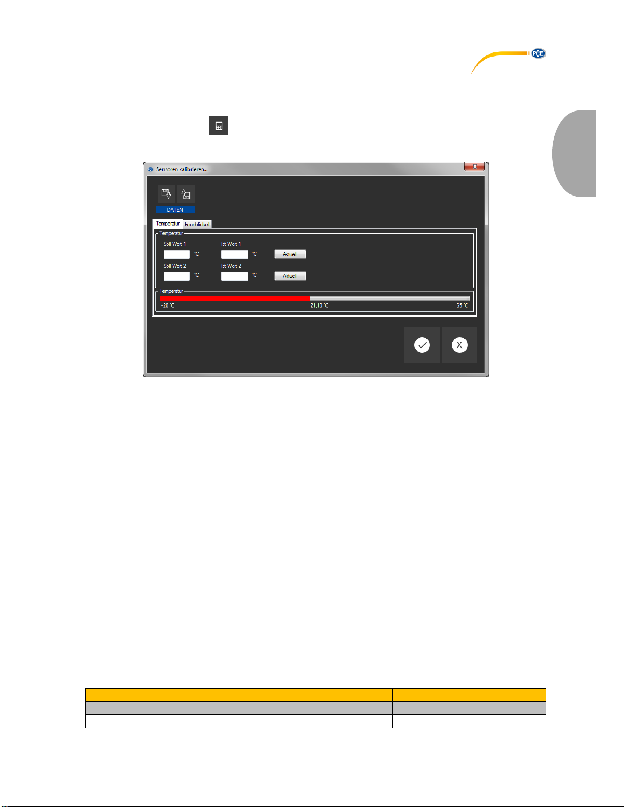
6.7 2 Punkt Kalibrierung der Sensoren Temperatur und Feuchte
Die Software gestattet das Kalibrieren vom Temperatur- und vom Feuchtesensor.
Ein Klick auf das Symbol in der Gruppe "Einstellungen" öffnet einen Dialog, der die
Kalibrierung dieser zwei Sensoren ermöglicht.
Der Kalibrier-Dialog
Die Vorgehensweise ist wie folgt:
- Auswahl eines Sensors (Temperatur oder Feuchte)
- Soll-Wert 1 und Ist-Wert 1 manuell eintragen.
- Soll-Wert 2 und Ist-Wert 2 manuell eintragen.
- Auswahl des zweiten Sensors (Feuchte oder Temperatur)
- Soll-Wert 1 und Ist-Wert 1 manuell eintragen.
- Soll-Wert 2 und Ist-Wert 2 manuell eintragen.
- Mit Mausklick auf "Übernehmen" bestätigen.
Ein Klick auf die jeweilige Schaltfläche "Aktuell" überträgt den aktuellen Sensorwert in das Feld
des entsprechenden Ist-Wertes.
Da die Kalibrier-Daten auch gespeichert und geladen werden können, ist es jederzeit möglich,
den Vorgang zu unterbrechen, indem die momentanen Daten gespeichert und zu einem
späteren Zeitpunkt wieder geladen werden.
Erst wenn bei beiden Sensoren beide Soll- und Ist-Werte mit gültigen Werten bestückt wurden,
lässt sich der Kalibrier-Dialog per Klick auf die "Übernehmen"-Schaltfläche schließen und die
Kalibrier-Daten an den Datenlogger übertragen.
Für die Soll- und Ist-Werte müssen bestimmte Wertebereiche eingehalten werden.
Näheres hierzu in der Tabelle "Kalibrier-Daten":
Sensor
Mindestabstand Referenzpunkte
Höchstabstand Soll/Ist
Temperatur
20 °C
1 °C
Feuchte
20 %RH
5 %RH
© PCE Instruments
15
Deutsch
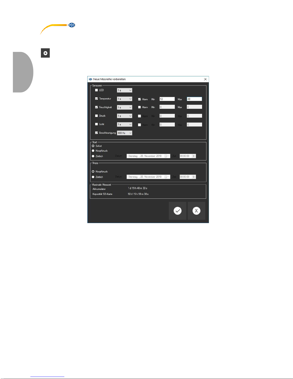
6.8 Starten einer Messung
Um eine neue Messung für den "VDL X" vorzubereiten, genügt ein Mausklick auf das Symbol
in der Gruppe "Datenlogger".
In dem nun dargestellten Fenster können nicht nur die beteiligten Sensoren, sondern auch die
Start- und Stoppbedingungen festgelegt werden.
In dem ausgewiesenen Bereich "Sensoren" können die zur Verfügung stehenden Sensoren des
Datenloggers mit in eine Messung einbezogen werden, indem Sie vor den gewünschten
Sensoren ein Häkchen setzen. Erscheint dort ein Häkchen, so wird der Sensor an der Messung
beteiligt. Gleichzeitig kann auch eingestellt werden, ob die LOG LED während der Messungen
blinkt.
Für jeden Sensor kann zudem eine Messrate konfiguriert werden.
Bei den Sensoren für Temperatur, Feuchtigkeit, Druck und Licht ist dies im Bereich von 1
Sekunde bis 1800 Sekunden (30 Minuten) möglich.
Hier gilt: je kleiner der Wert, desto häufiger wird gemessen.

© PCE Instruments
16
Deutsch
Bei den drei Beschleunigungssensoren hingegen kann zwischen einem Hertz und
800 bzw. 1600 Hertz (je nach Bauart) gewählt werden.
Hier gilt: je größer der Wert, desto häufiger wird gemessen.
Für die Sensoren für Temperatur, Feuchtigkeit, Druck und Licht können zudem Alarmwerte
festgelegt werden.
Hierzu wird ein Minimal- und ein Maximalwert als Unter- und Obergrenze festgelegt.
Liegen die gemessenen Werte mindestens eines dieser Sensoren außerhalb des festgelegten
Bereichs, so ist dies sofort an der rot blinkenden LED des Datenloggers zu erkennen.
Sobald sich alle Messwerte wieder im festgelegten Bereich befinden, erlischt die rote LED.
Eine Messung kann auf drei verschiedene Arten gestartet werden:
- Sofort:
Sobald das Fenster zum Starten einer Messung per Mausklick auf die "Übernehmen"Schaltfläche geschlossen wird, startet die Messung.
- Tastendruck:
Erst wenn die Taste zum Starten/Stoppen einer Messung am Datenlogger betätigt wird, startet
auch die Messung.
- Zeitlich:
Hierfür kann ein Datum und eine Zeit festgelegt werden.
Hinweis 1:
Ein Mausklick auf die Schaltfläche "Zeit" setzt die dort im Fenster angezeigte Zeit auf die aktuelle
Uhrzeit des PCs.
Hinweis 2:
Der Datenlogger synchronisiert jedes Mal seine interne Uhr mit der Uhrzeit des PCs, wenn eine
neue Messung vorbereitet wird.
Das Beenden einer Messung kann auf zwei verschiedene Arten erfolgen:
- Knopfdruck:
Die Messung endet erst dann, wenn die Taste zum Starten/Stoppen einer Messung am
Datenlogger betätigt wird.
- Zeitlich:
Hierfür kann ein Datum und eine Zeit festgelegt werden.
Hinweis:
Ein Mausklick auf die Schaltfläche "Zeit" setzt die dort im Fenster angezeigte Zeit auf die aktuelle
Uhrzeit des PCs.
Selbstverständlich kann eine laufende Messung auch jederzeit manuell über die Software
beendet werden: hierzu genügt ein Mausklick auf das Symbol in der Gruppe "Datenlogger".

© PCE Instruments
17
Deutsch
6.9 Übertragen und Laden von Messreihen
Die Messwerte einer laufenden Messung werden im Datenlogger auf einer microSD-Karte
abgelegt.
Wichtig:
Es können Dateien mit maximal 2.500.000 Messwerten auf direktem Weg in der Software
verarbeitet werden.
Dies entspricht einer ungefähren Dateigröße von 20 MB auf der SD-Karte.
Dateien, die mehr Messwerte aufweisen, können nicht direkt geladen werden.
Es gibt nun zwei Möglichkeiten diese Dateien vom Datenlogger an den PC zu übertragen:
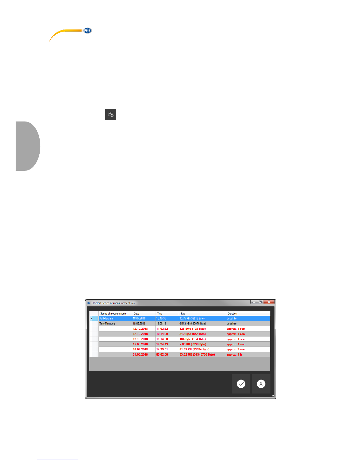
- Ein Mausklick auf das Symbol in der Gruppe "Messreihen" öffnet ein neues Fenster mit der
Auswahl von zur Verfügung stehenden Dateien mit Messdaten.
Da die Dateien mit Messwerten je nach eingestellter Messrate sehr schnell sehr groß werden
können, werden sie nach einmaliger Übertragung vom Datenlogger auf den PC in einem
Zwischenspeicher auf dem PC gehalten, so dass weitere Zugriffe darauf erheblich schneller
erfolgen können.
Anmerkung:
Der Datenlogger arbeitet mit einer Übertragungsrate von maximal 115200 Baud.
Daraus resultiert eine zur Kommunikation ausreichend schnelle, jedoch zur Übertragung von
vielen Daten, bedingt durch große Dateien, eher ungeeignete Datenrate.
Das Fenster mit der Auflistung der Messreihen wird daher zweifarbig dargestellt:
Einträge in schwarzer Schrift ("lokale Datei") entsprechen Messreihen, die sich bereits in dem
schnellen Zwischenspeicher ("Cache") des PCs befinden.
In rot und fetterer Schrift dargestellte Einträge, bei denen zudem eine Schätzung der Ladezeit
angegeben wird, befinden sich bislang ausschließlich auf der SD-Karte des Datenloggers.
Es gibt aber auch eine wesentlich schnellere Art, neue Messreihen an die Software zu übertragen.
Hierzu wird die SD-Karte aus dem Datenlogger entfernt und in einen passenden USB-Adapter
eingeführt (externes USB-Laufwerk).
Dieses Laufwerk kann im Windows-Explorer angezeigt und anschließend die darauf befindlichen
Dateien (einzeln oder auch zu mehreren) per "drag & drop" in das Fenster der Software importiert
werden.
Nach diesem Vorgang stehen alle Messreihen im schnellen Zwischenspeicher ("Cache") des PCs
zur Verfügung.
Wenn eine Messreihe geöffnet wird, kann auch ein eigener Name hierfür vergeben werden.
Auflistung der Messreihen

© PCE Instruments
18
Deutsch
6.10 Löschen von Messreihen
Eine in den Speicher der Software geladene Messreihe kann auf zwei Arten wieder aus dem
Speicher entfernt werden:
- In der Auflistung der geladenen Messreihen eine Messreihe auswählen und dann die "Entf"Taste betätigen.
oder
- In der Auflistung der geladenen Messreihen eine Messreihe auswählen und dann
das Symbol in der Gruppe "Messreihen" anklicken.
Eine so entfernte Messreihe kann jederzeit wieder aus dem Schnellspeicher geladen werden.
Soll eine Messreihe hingegen endgültig gelöscht werden, so erfolgt dies per Klick auf das Symbol
in der Gruppe "Messreihen".
Hier wird zunächst - ähnlich wie beim Laden von Messreihen - ein Fenster mit einer Übersicht
aller Messreihen angezeigt, die sich im Schnellzugriff des PCs oder ausschließlich auf der SDKarte eines verbundenen Datenloggers befinden.
Hier kann nun eine oder auch mehrere Messreihen ausgewählt werden, die gelöscht werden
sollen.
Es erfolgt eine Sicherheitsabfrage, ob diese Messreihen tatsächlich gelöscht werden sollen.
Je nachdem, wo sich die zu löschenden Messreihen befinden, werden sie entweder nur aus dem
Schnellzugriff des PCs, oder auch von der SD-Karte des Datenloggers gelöscht.
Anmerkung: Bitte bedenken Sie, dass diese Art des Löschens endgültig ist!

© PCE Instruments
19
Deutsch
6.11 Die Auswertung von Messreihen
Die Software des Datenloggers bietet verschiedene Arten von Ansichten, mit denen die
Sensordaten der Messreihen visualisiert werden können.
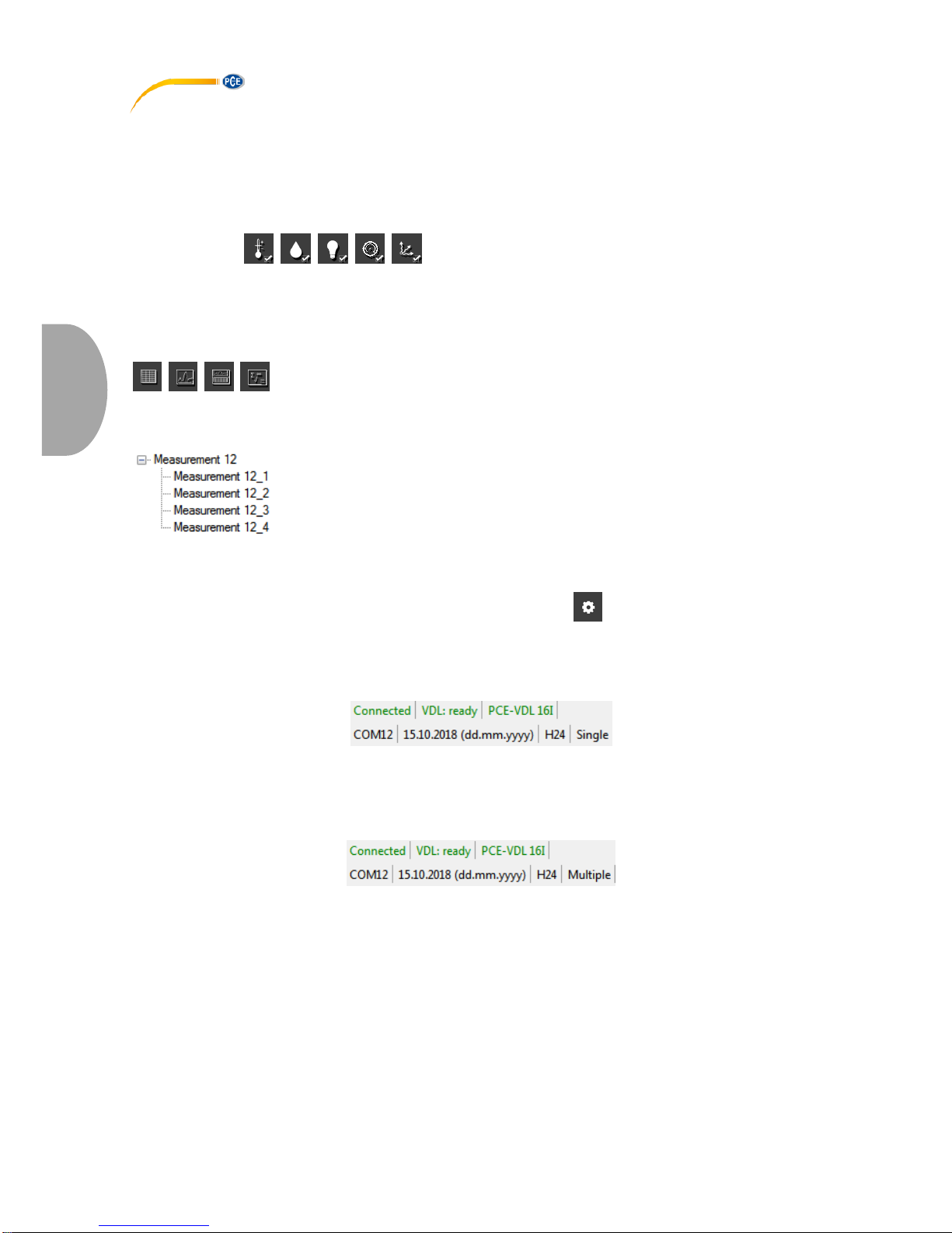
Sobald mindestens eine Messreihe geladen und ausgewählt wurde, kann per Klick auf eines der
Symbole . einer oder mehrere Sensoren ausgewählt werden.
Nach der Auswahl der Sensoren erfolgt die Auswahl der Visualisierung. Hierzu gibt es bei den
Symbolen die Gruppe "Ansichten".
Sobald mindestens ein Sensor ausgewählt wurde, kann per Klick auf eines der Symbole
eine entsprechende Ansicht in Form eines neuen Fensters geöffnet werden.
Alle Fenster, die zu einer Messreihe gehören, werden in der Auflistung im linken Bereich des
Hauptfensters unterhalb der entsprechenden Messreihe aufgelistet.
Beispiel: vier Ansichten, die zu einer Messreihe gehören
Im "Einstellungs-Dialog", der mit dem Symbol aus der Gruppe "Einstellungen" aufgerufen
werden kann, gibt es für die Ansicht zwei Auswahlmöglichkeiten:
- "Nur Fenster der aktuellen Messreihe darstellen" ("Single" in der Statuszeile)
bzw.
- "Sämtliche Fenster aller Messreihen darstellen" ("Multiple" in der Statuszeile)
Sollen nur die Fenster der aktuellen Messreihe dargestellt werden, so werden bei einer Änderung
der Auswahl der aktuellen Messreihe alle Ansichten mit Ausnahme der der aktuellen Messreihe
ausgeblendet.
Diese (Standard-)Einstellung macht Sinn, wenn man mehrere Messreihen in der Software
geöffnet haben möchte, aber immer nur eine davon betrachten möchte.
Die andere Option erlaubt die Anzeige aller Ansichten von allen geöffneten Messreihen.
Diese Einstellung macht dann Sinn, wenn man nur sehr wenige Messreihen gleichzeitig geöffnet
hat, diese dann aber miteinander vergleichen möchte.

© PCE Instruments
20
Deutsch
6.11.1 Tabellarische Ansicht
Die tabellarische Ansicht gestattet den numerischen Überblick zu einer Messreihe.
Die zuvor ausgewählten Sensoren werden spaltenweise nebeneinander dargestellt.
Die ersten vier Spalten geben hierbei stets Auskunft über den zeitlichen Ablauf.
Die Tabelle kann nach jeder ihrer Spalten sortiert werden, indem mit der Maus auf die
Spaltenüberschrift geklickt wird.
Sind eine oder mehrere Zeilen markiert, so kann per Tastenkombination "Strg + C" der Inhalt
dieser Zeilen in die Zwischenablage übernommen und von dort aus per Tastenkombination
"Strg + V" aus der Zwischenablage entnommen und eingefügt werden.
Datenexport
Über die Schaltfläche "Datenexport" kann entweder eine zuvor getroffene Auswahl von
Zeilen oder auch der komplette Inhalt der Tabelle im CSV-Format exportiert werden.
Auswahl: Nur selektierte oder alle Datensätze?

© PCE Instruments
21
Deutsch
6.11.2 Statistiken
Diese Ansicht bietet statistische Daten zu einer Messreihe.
Die zuvor ausgewählten Sensoren werden auch hier spaltenweise nebeneinander dargestellt.
Zur Verfügung stehen hier die folgenden Angaben:
Anzahl der Messpunkte, Minimum und Maximum, der Durchschnitt, die Standardabweichung, die
Varianz, die Spanne, der Standardfehler und (optional) der Median.
Sind eine oder mehrere Zeilen markiert, so kann per Tastenkombination "CTRL + C" der Inhalt
dieser Zeilen in die Zwischenablage übernommen und von dort aus per Tastenkombination
"CTRL + V" wieder entnommen werden.
Datenexport
Über die Schaltfläche "Datenexport" kann entweder eine zuvor getroffene Auswahl von
Zeilen oder auch der komplette Inhalt der Tabelle im CSV-Format exportiert werden.
Auswahl: Nur selektierte oder alle Datensätze?

© PCE Instruments
22
Deutsch
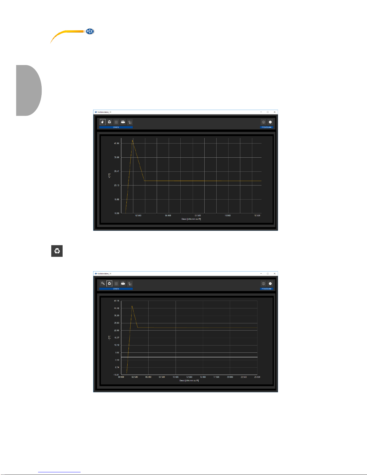
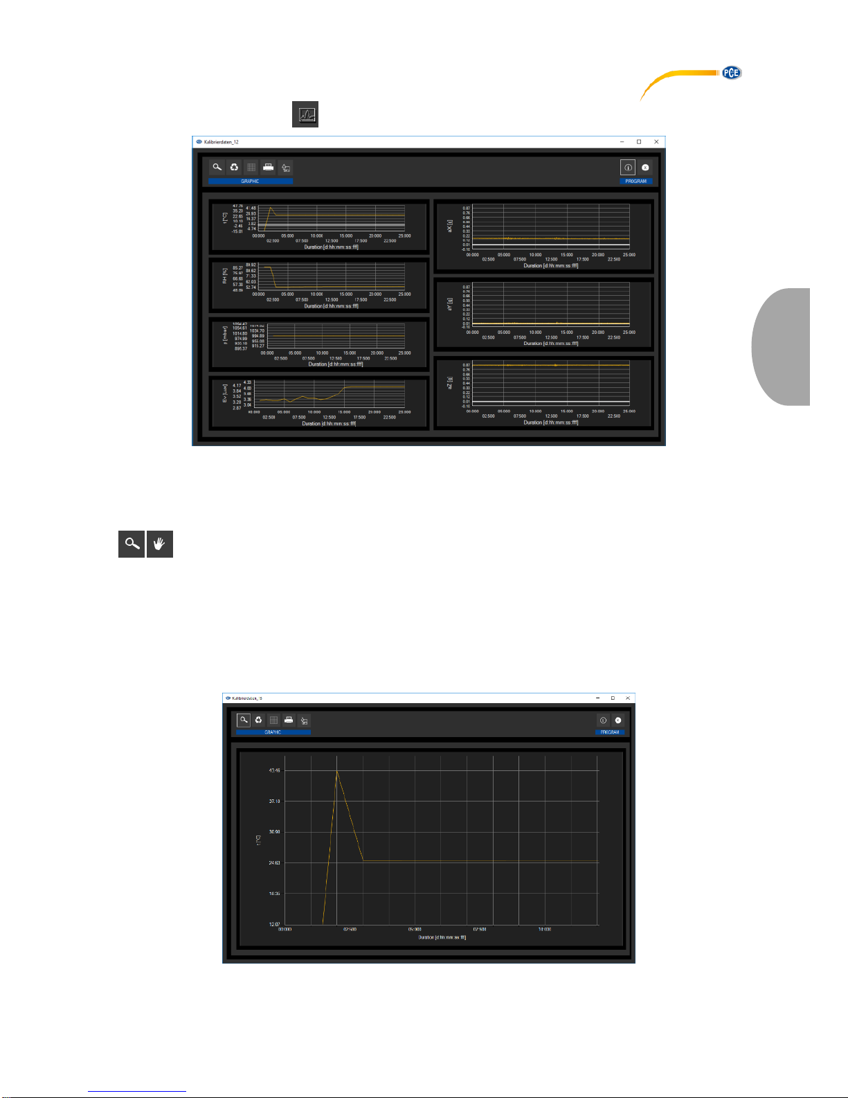
6.11.3 Grafische Ansicht
Diese Ansicht stellt die Werte der zuvor ausgewählten Sensoren grafisch dar, wobei der Messwert
des Sensors mit seiner spezifischen Einheit auf der y-Achse und der zeitliche Verlauf (Dauer) auf
der x-Achse zu finden ist.
Vergrößerung eines Grafikbereichs ("Zoomen") bzw. Bewegen der vergrößerten Grafik
Die dargestellte Grafik kann in einem frei wählbaren Teilbereich vergrößert dargestellt werden.
Hierzu muss das entsprechende Symbol in der Symbolleiste ("Vergrößerung eines Grafikbereichs
("Zoomen") bzw. Bewegen der vergrößerten Grafik") eine "Lupe" darstellen.
Dann kann bei gedrückt gehaltener Maustaste ein Rechteck über einen Bereich der Grafik
gezogen werden. Sobald die Maustaste losgelassen wird, erscheint der ausgewählte Bereich als
neue Grafik.
"Zoomen" der Grafik
© PCE Instruments
23
Deutsch
Sobald mindestens einmal eine Vergrößerung vorgenommen wird, kann per Klick auf das Symbol
("Vergrößerung eines Grafikbereichs ("Zoomen") bzw. Bewegen der vergrößerten Grafik") mit der
"Lupe" aus dem Vergrößerungs-Modus in den Verschiebe-Modus umgeschaltet werden.
Dieser Modus wird durch das "Hand"-Symbol dargestellt.
Wird nun die Maus über den Grafikbereich gebracht und dann die linke Maustaste gedrückt, so
kann der abgebildete Teilausschnitt mit gehaltener Maustaste verschoben werden.
Ein erneuter Klick auf das "Hand"-Symbol wechselt wieder in den Vergrößerungs-Modus,
erkennbar durch das "Lupe"-Symbol.
Verschieben der "gezoomten" Grafik
Wiederherstellung der originalen Grafik
Wiederhergestellte (originale) Grafik
Die originale Grafik kann jederzeit wiederhergestellt werden, indem auf das entsprechende
Symbol ("Wiederherstellung der originalen Grafik") neben der Lupe bzw. Hand geklickt wird.

© PCE Instruments
24
Deutsch
Hintergrund und Darstellung der Grafik ändern
Über das rechts daneben befindliche Symbol ("Hintergrund und Darstellung der Grafik ändern")
kann der Hintergrund der Grafik und auch deren Darstellung geändert werden.
Ein Klick auf das Symbol wirkt hierbei wie ein Umschalter: Ein einfacher Klick stellt den
Hintergrund feiner aufgeteilt und die Grafik selbst mit zusätzlich dargestellten Punkten dar.
Ein weiterer Klick auf das Symbol wechselt wieder zur Standardansicht.
Feinere Auflösung und eingeblendete Punkte
Solange auch die einzelnen Punkte dargestellt werden, sorgt ein Führen des Mauszeigers auf
einen Punkt der dargestellten Linie nach kurzer Zeit für das Anzeigen eines kleinen
Informationsfensters mit den Daten (Zeit und Einheit) des aktuell ausgewählten Messwerts.
Informationen zu einem ausgewählten Punkt
© PCE Instruments
25
Deutsch
Drucken der aktuell sichtbaren Grafik
Die aktuell angezeigten Grafiken können auch ausgedruckt werden.
Ein Klick auf das entsprechende Symbol ("Drucken der aktuell sichtbaren Grafik") öffnet den
bekannten "Drucken"-Dialog.
Speichern der aktuell sichtbaren Grafik
Die aktuell angezeigten Grafiken können auch abgespeichert werden.
Durch einen Klick auf das entsprechende Symbol ("Speichern der aktuell sichtbaren Grafik") kann
der Speicherort für die Grafiken festgelegt werden.
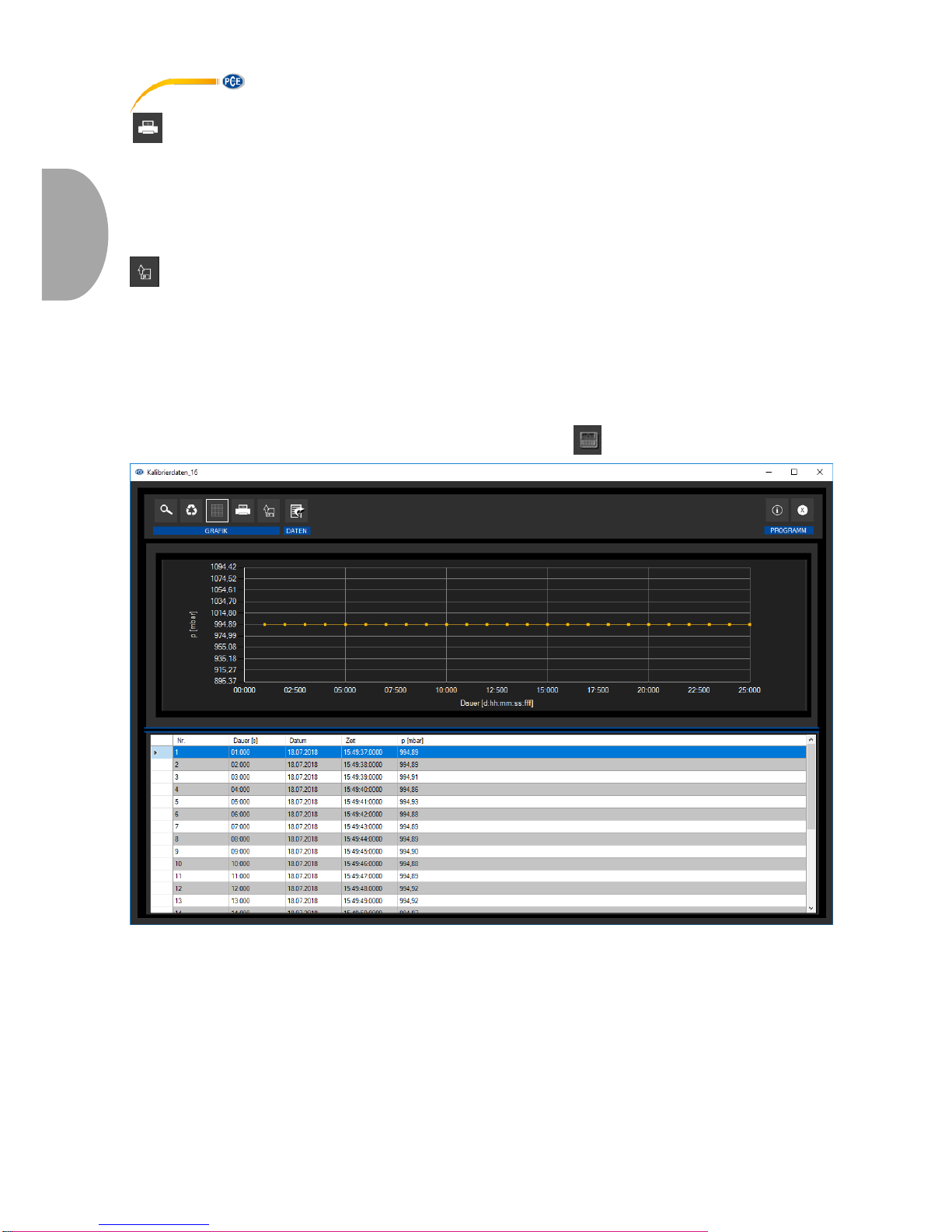
6.11.4 Gemischte Ansicht (grafisch plus tabellarisch)
Diese Ansicht besteht aus der grafischen, zusammen mit der tabellarischen Ansicht.
Der Vorteil bei dieser Ansicht ist der Zusammenhang zwischen beiden Ansichten:
Ein Doppelklick auf einen der Punkte in der grafischen Ansicht selektiert automatisch den
passenden Eintrag in der tabellarischen Ansicht.

© PCE Instruments
26
Deutsch
7 Mögliche Fehlermeldungen
Quelle
Code
Text
SD-Karte
65
Schreib- oder Lesefehler
SD-Karte
66
Datei kann nicht geöffnet werden
SD-Karte
67
Das Verzeichnis auf der SD-Karte ist unlesbar
SD-Karte
68
Eine Datei konnte nicht gelöscht werden
SD-Karte
69
Es wurde keine SD-Karte gefunden
Beispiel: " Es wurde keine SD-Karte gefunden"
© PCE Instruments
27
Deutsch
8 Garantie
Unsere Garantiebedingungen können Sie in unseren Allgemeinen Geschäftsbedingungen
nachlesen, die Sie hier finden: https://www.pce-instruments.com/deutsch/agb.
9 Entsorgung
HINWEIS nach der Batterieverordnung (BattV)
Batterien dürfen nicht in den Hausmüll gegeben werden: Der Endverbraucher ist zur Rückgabe
gesetzlich verpflichtet. Gebrauchte Batterien können unter anderem bei eingerichteten
Rücknahmestellen oder bei der PCE Deutschland GmbH zurückgegeben werden.
Annahmestelle nach BattV:
PCE Deutschland GmbH
Im Langel 4
59872 Meschede
Zur Umsetzung der ElektroG (Rücknahme und Entsorgung von Elektro- und Elektronikaltgeräten)
nehmen wir unsere Geräte zurück. Sie werden entweder bei uns wiederverwertet oder über ein
Recyclingunternehmen nach gesetzlicher Vorgabe entsorgt. Alternativ können Sie Ihre Altgeräte
auch an dafür vorgesehenen Sammelstellen abgeben.
WEEE-Reg.-Nr.DE69278128

© PCE Instruments
28
English
1 Safety notes
Please read this manual carefully and completely before you use the device for the first time. The
device may only be used by qualified personnel and repaired by PCE Instruments personnel.
Damage or injuries caused by non-observance of the manual are excluded from our liability and
not covered by our warranty.
• The device must only be used as described in this instruction manual. If used otherwise,
this can cause dangerous situations for the user and damage to the meter.
• The instrument may only be used if the environmental conditions (temperature, relative
humidity, …) are within the ranges stated in the technical specifications. Do not expose
the device to extreme temperatures, direct sunlight, extreme humidity or moisture.
• Do not expose the device to shocks or strong vibrations.
• The case should only be opened by qualified PCE Instruments personnel.
• Never use the instrument when your hands are wet.
• You must not make any technical changes to the device.
• The appliance should only be cleaned with a damp cloth. Use only pH-neutral cleaner,
no abrasives or solvents.
• The device must only be used with accessories from PCE Instruments or equivalent.
• Before each use, inspect the case for visible damage. If any damage is visible, do not
use the device.
• Do not use the instrument in explosive atmospheres.
• The measurement range as stated in the specifications must not be exceeded under
any circumstances.
• Non-observance of the safety notes can cause damage to the device and injuries to
the user.
We do not assume liability for printing errors or any other mistakes in this manual.
We expressly point to our general guarantee terms which can be found in our general terms of
business.
If you have any questions please contact PCE Instruments. The contact details can be found at
the end of this manual.
2 Specifications
2.1 Technical specifications
Specification
Value
Memory capacity
2.5 million readings per measurement
3.2 billion readings with included 32 GB microSD card
IP protection class
IP40
Voltage supply
integrated rechargeable Li-Ion battery 3.7 V / 500 mAh
Battery charged via USB interface
Interface
micro USB
Operating conditions
Temperature -20 ... +65 °C
Storage conditions
(ideal for battery)
Temperature +5 ... +45 °C
10 ... 95 % relative humidity, non-condensing
Weight
approx. 60 g
Dimensions
86.8 x 44.1 x 22.2 mm
© PCE Instruments
29
English
2.2 Specifications of the different integrated sensors
Specification
PCE-VDL 16I (5 sensors)
PCE-VDL 24I (1 sensor)
Temperature °C
Measurement range
-20 … 65 °C
Accuracy
±0.2 °C
Resolution
0.01 °C
Max. sampling rate
1 Hz
Relative humidity
Measurement range:
0 … 100 % RH
Accuracy
±1.8 % RH
Resolution
0.04 % RH
Max. sampling rate
1 Hz
Atmospheric
pressure
Measurement range
10 … 2000 mbar
Accuracy
±2 mbar (750 … 1100 mbar);
otherwise ±4 mbar
Resolution
0.02 mbar
Light
Measurement range
0.045 … 188,000 lux
Resolution
0.045 lux
Max. sampling rate
1 Hz
3 axes acceleration
Measurement range
±16 g
±16 g
Accuracy
±0.24 g
±0.24g
Resolution
0.00390625 g
0.00390625 g
Max. sampling rate
800 Hz
1600 Hz
2.3 Specification of the battery life
Sampling rate [Hz]
Battery life PCE-VDL 16I
Battery life PCE-VDL 24I
1 Hz
2d 06h 21min
1d 14h 59min
3 Hz
2d 06h 12min
1d 14h 54min
6 Hz
2d 05h 57min
1d 14h 48min
12 Hz
2d 05h 28min
1d 14h 34min
25 Hz
2d 04h 27min
1d 14h 06min
50 Hz
2d 02h 33min
1d 13h 13min
100 Hz
1d 23h 03min
1d 11h 32min
200 Hz
1d 17h 05min
1d 08h 32min
400 Hz
1d 08h 39min
1d 03h 48min
800 Hz
1d 00h 39min
0d 22h 09min
1600 Hz
0d 15h 46min

© PCE Instruments
30
English
The specification of the battery life is based on the assumption that the battery is new and fully
charged and that the included microSD card, type TS32GUSD300S-A, is used.

© PCE Instruments
31
English
2.4 Specification of the measuring time (2,500,000 readings)
Sampling rate [Hz]
Measuring time PCE-VDL
16I
Measuring time PCEVDL 24I
1 Hz
5d 18h 53min
28d 22h 26min
3 Hz
4d 03h 12min
9d 15h 28min
6 Hz
2d 05h 58min
4d 19h 44min
12 Hz
1d 19h 24min
2d 09h 52min
25 Hz
0d 23h 56min
1d 03h 46min
50 Hz
0d 12h 51min
0d 13h 53min
100 Hz
0d 06h 40min
0d 06h 56min
200 Hz
0d 03h 24min
0d 03h 28min
400 Hz
0d 01h 43min
0d 01h 44min
800 Hz
0d 00h 51min
0d 00h 52min
1600 Hz
0d 00h 26min
The specified measuring times and sampling rates only apply in combination with the microSD
card, type TS32GUSD300S-A, which comes with the meter.
2.5 Delivery contents
1x data logger PCE-VDL 16l or PCE-VDL 24I
1x data cable USB A – USB Micro
1x 32 GB microSD memory card
1x SD card ejector tool
1x USB pen drive with PC software and user manual
2.6 Optional accessories
Part number
Part description
PCE-VDL MNT
Adaptor plate with magnetic attachments, screw
holes and long holes
CAL-VDL 16I
Calibration certificate for PCE VDL 16I
CAL-VDL 24I
Calibration certificate for PCE VDL 24I

© PCE Instruments
32
English
3 System description
3.1 Introduction
Data loggers record parameters important for assessing mechanical and dynamic loads.
Transport monitoring, fault diagnosis and load tests are some of the most common areas of
application.
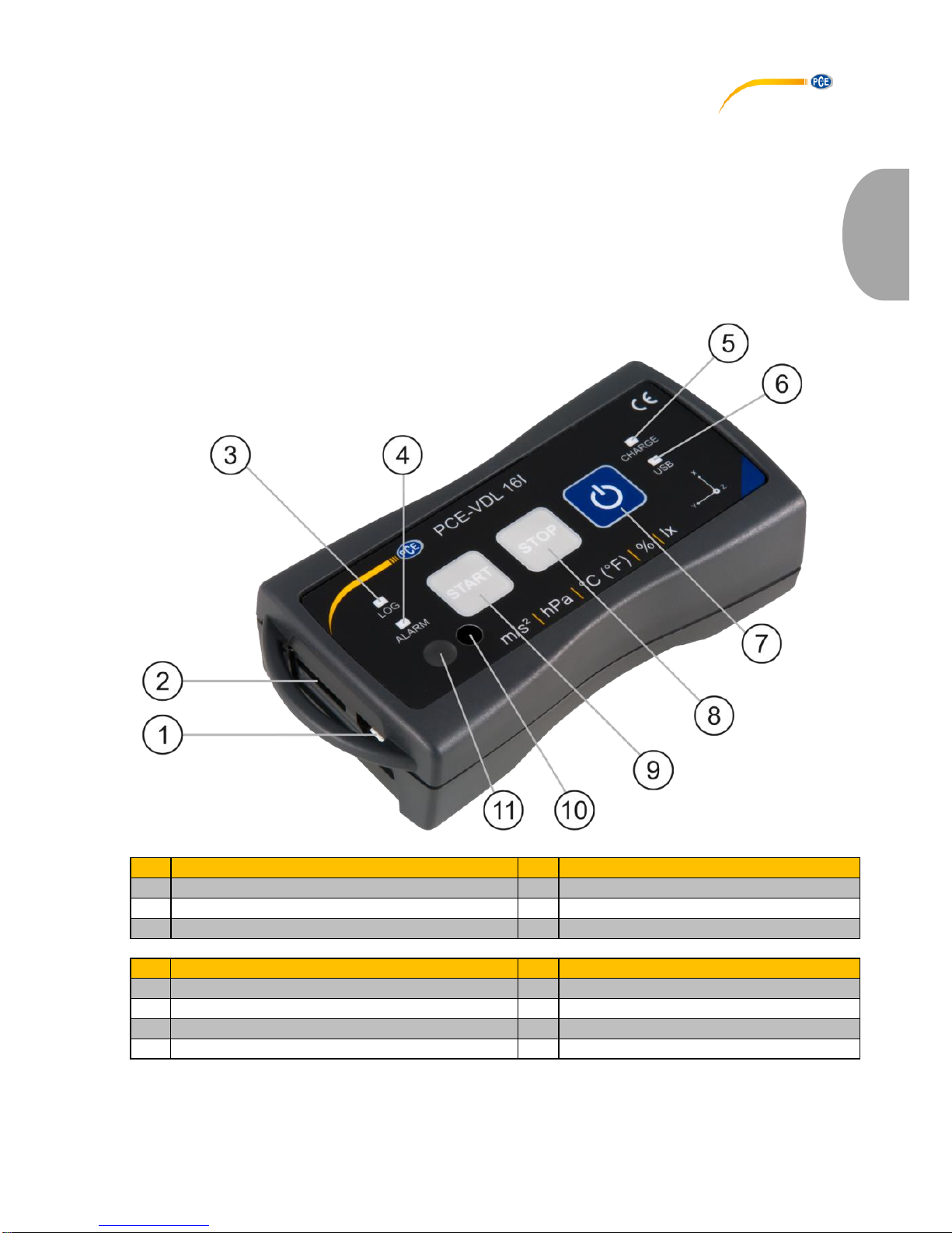
3.2 Device
Interfaces
Key functions
1
Data cable connection: Micro USB
7
On / off
2
SD card slot
8
STOP: stop the measurement
9
START: start the measurement
LED indicators
Sensor positions: PCE-VDL 16I only
3
LOG: status indicator / log interval
10
Humidity sensor
4
ALARM: red when limit value is exceeded
11
Light sensor
5
CHARGE: green when charging
6
USB: green when connected to PC

© PCE Instruments
33
English
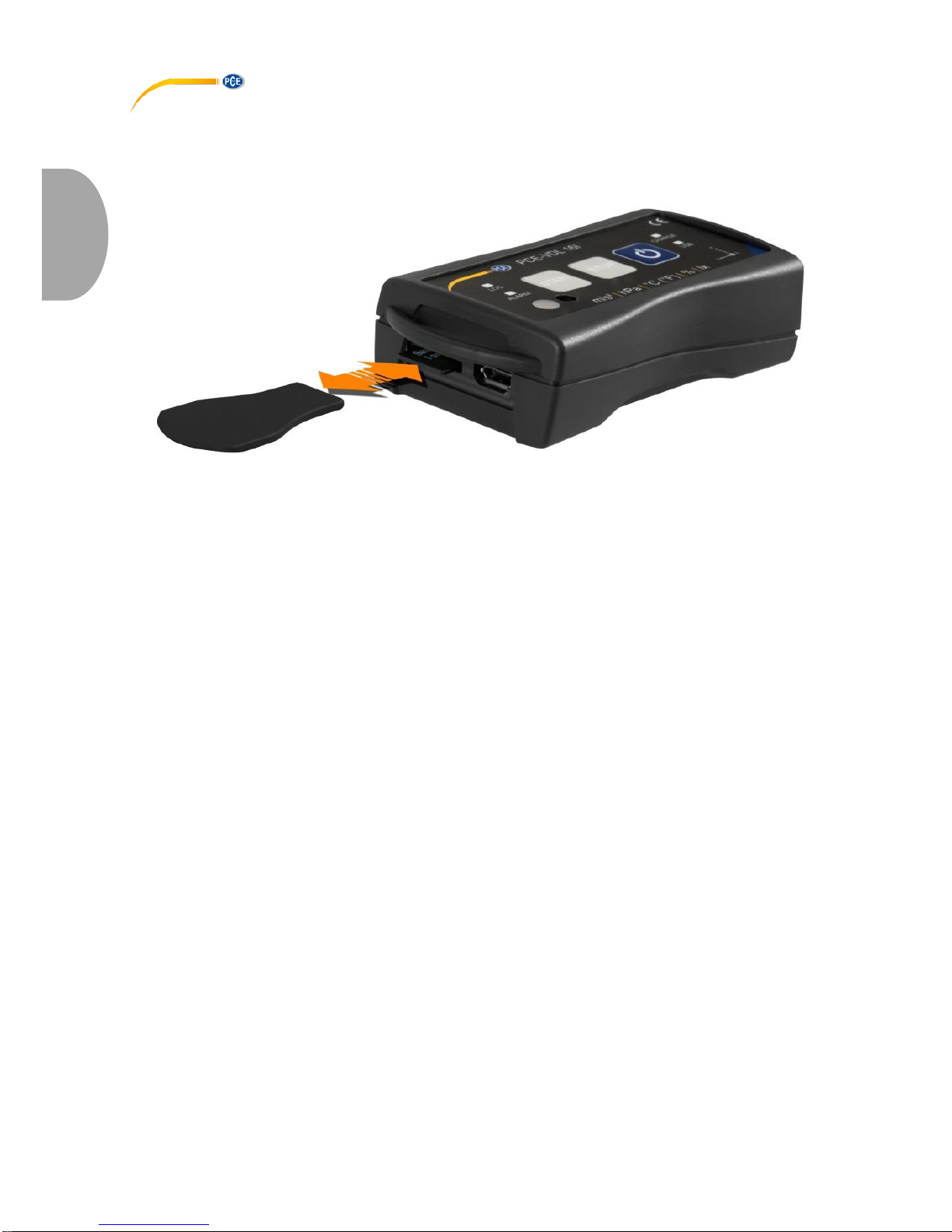
3.3 MicroSD card in the data logger
Insert the microSD card into the SD card slot with two fingers and use the SD card ejector tool to
push it until it snaps into place.
To remove the microSD card from the data logger, insert the ejector tool into the SD card slot.
The memory card is then released from ist retainer and snaps out of the case so that it can be
taken out.
To read out the data, insert the microSD card into a PC, together with its adaptor.
© PCE Instruments
34
English
4 Getting started
4.1 Attachment of the optional adaptor plate PCE-VDL MNT
You can attach the data logger to an adaptor plate. The data logger can then be attached to the
measurement object by means of the boreholes or the parallel long holes. The rear side of the
adaptor plate is magnetic so that it is no problem to attach it to magnetic substrates. The adaptor
plate is particularly useful when oscillation, vibration and shocks are recorded as the data logger
should be firmly attached to the measurement object to ensure accurate readings.
4.2 Attachment without using the adaptor plate
If you do not wish to use the optional adaptor plate PCE-VDL MNT, the data logger can be
attached in any position at the measurement object. If parameters like temperature, humidity or
air pressure and light are measured, it is normally sufficient to place or clamp the data logger onto
the measuring point. The data logger can also be suspended by its guard bracket.
4.3 SD card
If you use an SD card that is not part of the delivery contents, you have to format the SD card
before use (FAT32 file system). For high sampling rates of the acceleration sensor (800 Hz for
PCE-VDL 16I and 1600 Hz for PCE-VDL 24I), you will need at least a Class 10 (U1) microSD
card. The specification of the battery life only applies if the included microSD card is used.

© PCE Instruments
35
English
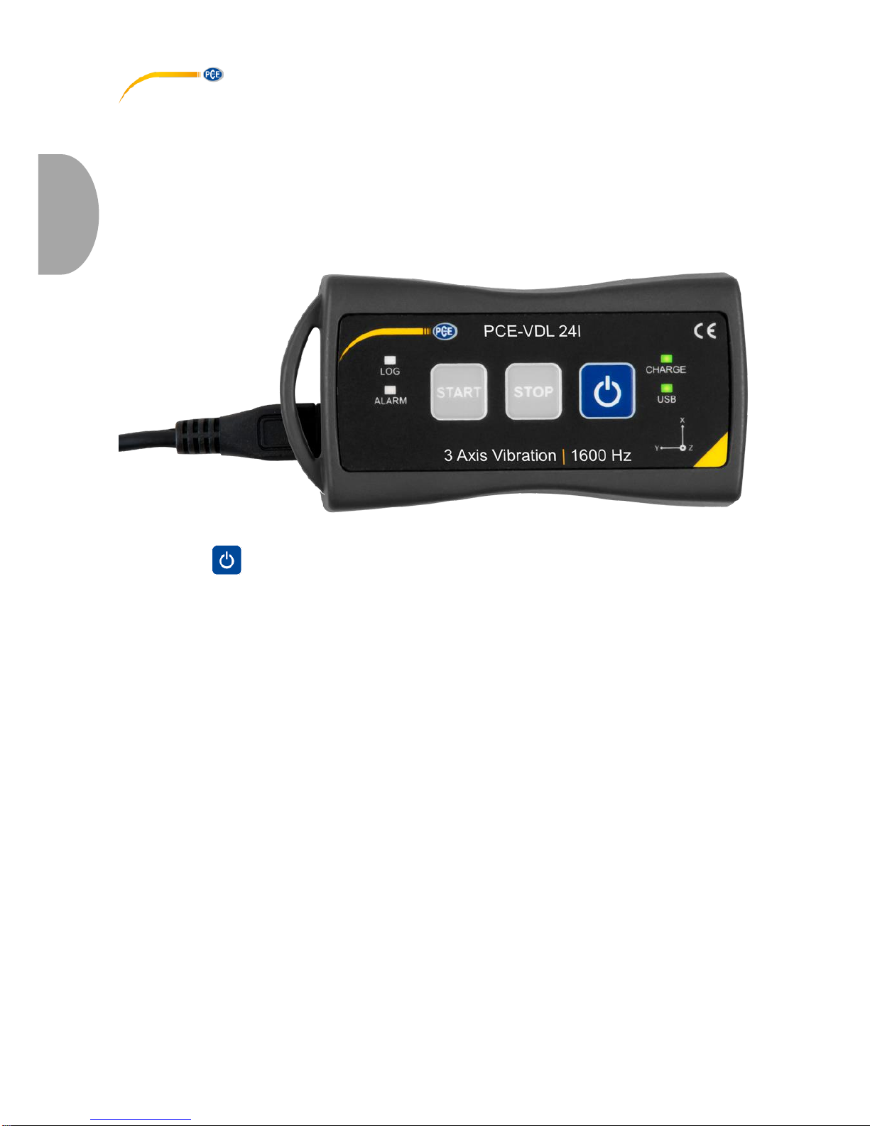
5 Operation
5.1 Connecting the data logger to your PC
To be able to make the different sensor settings in the software, connect the data cable to the PC
and to the Micro USB connection of the data logger. The Charge and USB LEDs glow. When the
battery is charged, the CHARGE LED will stop glowing automatically.
Press to turn on/off the data logger.
5.2 System requirements for PC software
• Operating system Windows XP SP3 or higher
• USB port (2.0 or higher)
• An installed .NET framework 4.0
• A minimum resolution of 800x600 pixels
• Optional: a printer
• Processor with 1 GHz
• 4 GB RAM
• A data logger ("PCE-VDL 16I" or "PCE-VDL 24I")
Recommended: Operating system (64 Bit) Windows 7 or higher
At least 8 GB main memory (the more, the better)
5.3 Software installation
Please run the " Setup PCE-VDL X.exe " and follow the instructions of the setup.

© PCE Instruments
36
English
5.4 Description of the user interface in the software
The main window consists of several areas:
Below the title bar there is a "toolbar", the icons of which are functionally grouped.
Below this toolbar, there is a list of measurement series, in the left part of the window.
The right-hand part of the window shows an overview of a selected series of measurements.
At the bottom of the main window there are two “status bars” containing important information,
directly above each other.
The lower of the two shows the static settings of the program which can be set via a settings
dialog.
The upper status bar shows the dynamic settings of the "PCE-VDL X" which are retrieved directly
from the connected device. This also applies to the information if a measurement is currently
made or what data logger model is connected ("PCE-VDL 16I" or "PCE-VDL 24I").
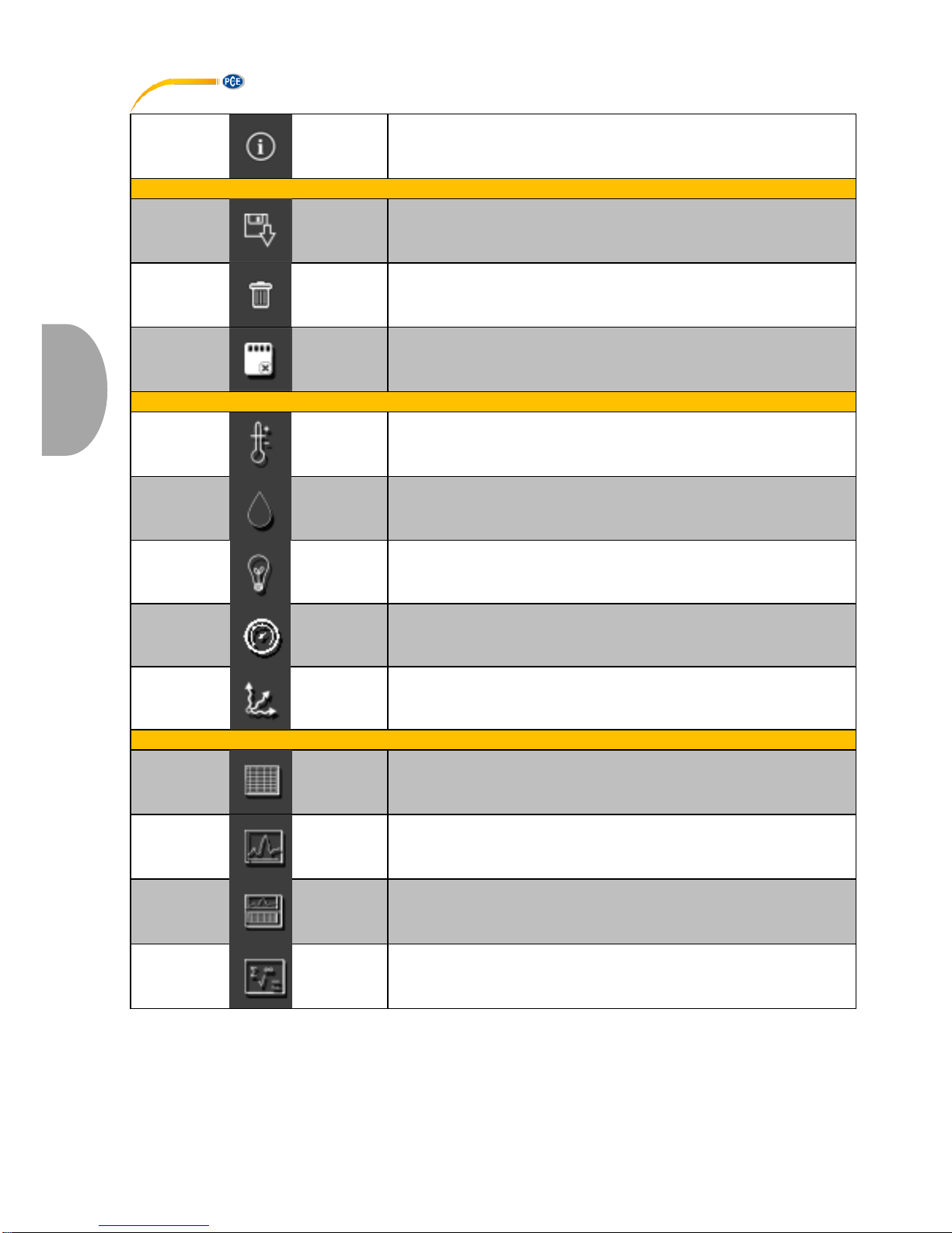
5.5 Meaning of the individual icons in the toolbar of the PC software
Group "Connection"
Connect to the "PCE-VDL X"
Disconnect from the "PCE-VDL X"
Group "Data Logger"
Start a measurement
Stop a measurement
Test sensors
© PCE Instruments
37
English
Information on a connected data logger
Group „Series of Measurements“
Load a series of measurements from cache
Remove series of measurements from program memory
Delete series of measurements permanently
Group „Sensors“
Temperature sensor
Humidity sensor
Light sensor
Pressure sensor
Acceleration sensor
Group „Views“
Tabular view
Graphical view
Graphical and tabular view
Statistics

© PCE Instruments
38
English
Group "Settings"
Open settings dialog for static device data
Open settings dialog for dynamic device data
Select one of the languages supported by the program
Group "Program"
Display an information dialog
Exit the program
6 Operation
6.1 The first use of the software
Before the "PCE-VDL X" can work with the software, the assigned COM port must be set in the
software once. It can be set via the “Settings” dialog .
In addition to the connection data, further settings for the different views of series of
measurements as well as for the date and time format can be made here.

© PCE Instruments
39
English
"Only show windows of current series of measurements" hides views that do not belong to the
currently selected series of measurements.
When this mode is active, the lower status bar of the main window will show the text "Single".
If you select “Show all windows of each series of measurements“ instead, all views of all loaded
series of measurements will be shown.
In this case, the lower status bar of the main window will show the text "Multiple“.
Via the button "Change...", the standard size of the windows for all views can be set.
6.2 Connect to the "PCE-VDL X"
After the desired settings have been made, close the Settings window by clicking on the "Apply"
button.
Turn on the data logger before you proceed.
Press the key.
The LOG LED starts flashing approx. every 10 seconds.
Now click on the icon in the toolbar of the main window, in the group „Connection“.
If the connection could be successfully established, the status bar for dynamic data will show, for
example, the following in green:
If the button changes to , this means that the connection is active.
6.3 Disconnect from the " PCE-VDL X"
By clicking on the icon, an active connection to the "PCE-VDL X" can be terminated. The
icon indicates that the connection has been interrupted.
By clicking on the icon, an active connection to the "PCE-322A" can be terminated.
6.4 Switch off the data logger
When the data logger is on, the LOG LED flashes.
Press the key when the meter is on to stop the LOG LED from flashing and to switch off the
data logger. In the display field of the status bar, you will see the following in green:
If the data logger is turned off manually, a new configuration via the button in the group “Data
Logger” is required, see chapter “Start a measurement”.
© PCE Instruments
40
English
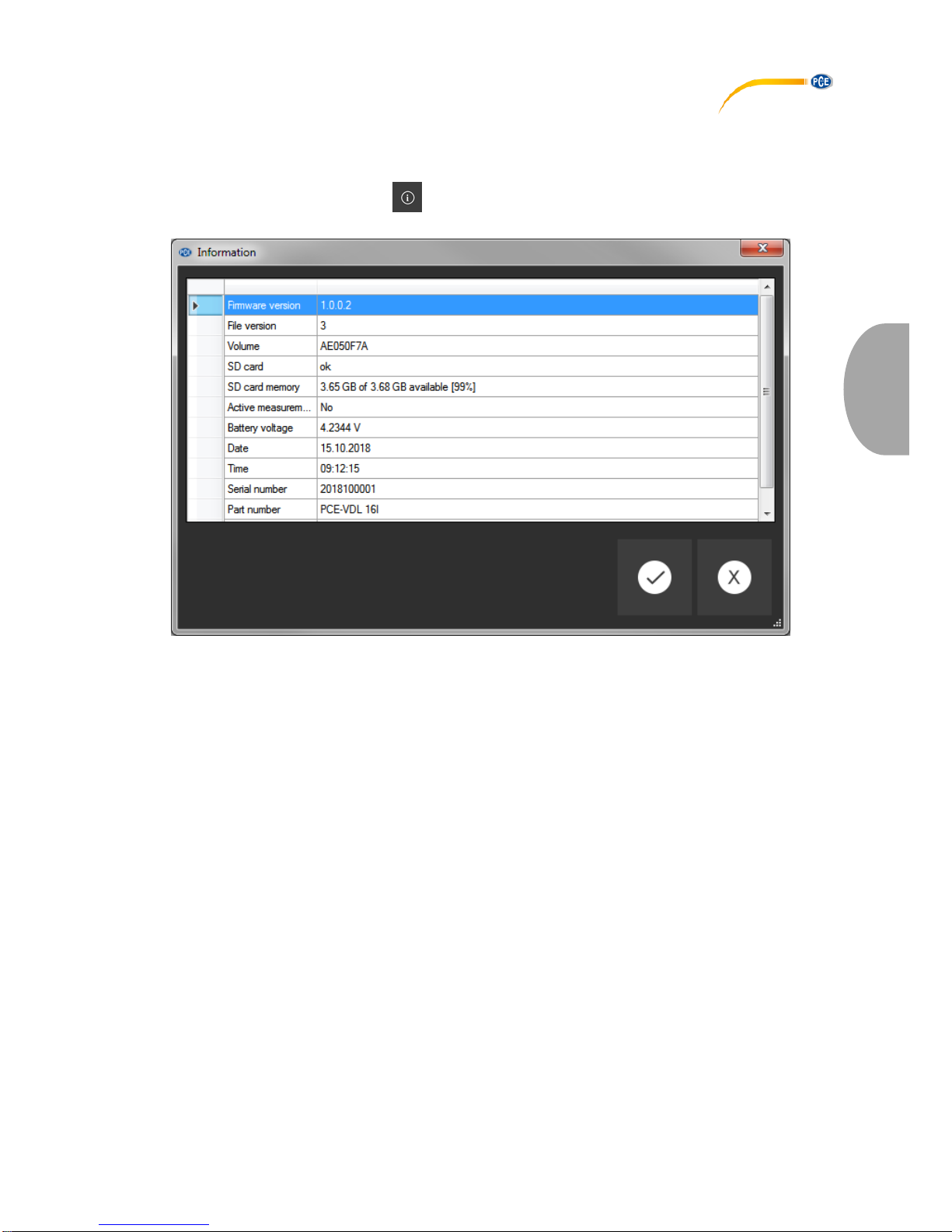
6.5 Retrieve information on connected data logger
If the connection to the "PCE-VDL X" was successfully established, some important information
on the data logger can be retrieved and displayed.
This is done by clicking on the icon in the group “Data Logger”.
Along with the firmware and file versions, the following information will be displayed here:
- the volume name, the status and the capacity of the SD card
- the status if there is an active measurement
- the current battery voltage
- date and time (optional)
- serial and part number of the VDL X
© PCE Instruments
41
English
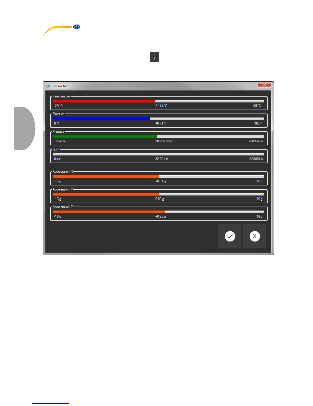
6.6 Test the sensors
When a connection to the "PCE-VDL X" is active, a window with the current values of all available
sensors can be displayed by clicking on the icon in the group "Data Logger".
Note: The values displayed in that window are continuously queried. This means that the data
are live data.
© PCE Instruments
42
English
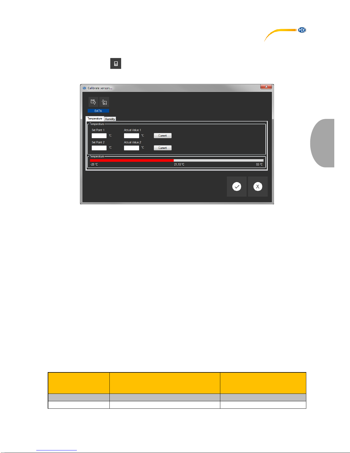
6.7 2-point calibration of the temperature and humidity sensors
The software allows calibration of the temperature sensor and of the humidity sensor.
By clicking on the icon in the group „Settings“, you can open a dialog for calibration of these
two sensors.
Calibration dialog
The procedure is as follows:
- Select sensor (temperature or humidity)
- Enter set point 1 and actual value 1 manually.
- Enter set point 2 and actual value 2 manually.
- Select second sensor (temperature or humidity)
- Enter set point 1 and actual value 1 manually.
- Enter set point 2 and actual value 2 manually.
- Confirm by clicking on "Apply".
When you click on the respective „Current“ button, the current sensor value will be entered in
the field for the respective actual value.
As the calibration data can be saved and loaded, it is always possible to interrupt the procedure
by saving the current data and loading them again later.
Closing the calibration dialog by clicking on the „Apply“ button and sending the calibration data
to the data logger is only possible if both set points and actual values of both sensors have
been assigned valid values.
For the set points and actual values, a certain range of values is available.
More information can be found in the chart "Calibration data":
Sensor
Minimum difference between
reference points
Maximum difference
between set point and actual
value
Temperature
20 °C
1° C
Humidity
20 % RH
5 % RH

© PCE Instruments
43
English
6.8 Start a measurement
To prepare a new measurement for the "VDL X", click on the icon in the group "Data Logger".
In the window that is now displayed, not only the involved sensors can be set but also the start
and stop conditions.
In the „Sensors“ area, the available sensors of the data logger can be included in a measurement
by ticking the box in front of the sensor name. At the same time, you can set if the LOG LED
should flash during the measurement.
You can also set a sampling rate for each sensor.
For the temperature, humidity, pressure and light sensors, you can set a sampling rate between
1 and 1800 s (30 minutes).
The smaller the value entered, the more measurements are made.
For the acceleration sensor, you can select a value between 1 and 800 / 1600 (depending on
your requirements).
The higher the value entered, the more measurements are made.
You can also set alarm values for the temperature, humidity, pressure and light sensors.

© PCE Instruments
44
English
You can set a minimum value as the lower limit and maximum value as the upper limit.
If the measured value of at least one of these sensors is outside this set range, the data logger’s
LED will flash in red.
The red LED will go off as soon as all readings are back within the set range.
A measurement can be started in three different ways:
- Instant:
When the window for starting a measurement is closed by clicking on „Apply“, the measurement
is started.
- By keystroke:
The measurement is started when the Start or Stop key of the data logger is pressed.
- By time:
You can set a date and time for starting a measurement.
Note 1:
By clicking on the „By time“ button, you can take over the current time of your PC as the time
shown in that window.
Note 2:
The data logger synchronizes its internal clock with the PC time every time a new measurement
is prepared.
A measurement can be stopped in two different ways:
- By keystroke:
The measurement is stopped when the Start or Stop key of the data logger is pressed.
- By time:
You can set a date and time for stopping a measurement.
Note:
By clicking on the „By time“ button, you can take over the current time of your PC as the time
shown in that window.
Of course, an ongoing measurement can always be terminated manually via the software, by
clicking on the icon in the group “Data Logger”.
© PCE Instruments
45
English
6.9 Transfer and load series of measurements
The readings of an ongoing measurement are saved to a microSD card in the data logger.
Important:
A file can contain a maximum of 2,500,000 readings to be processed directly by the
software.
This number is equivalent to a file size of approx. 20 MB.
Files that contain more readings per sensor cannot be loaded directly.
There are two ways to transfer these files from the data logger to the PC:
- A click on the icon in the group "Series of Measurements" opens a new window where the
available files with measurement data are listed.
As the files with measurement data can easily become quite large, depending on the set sampling
rate, these are saved to a buffer on the PC after they have been transferred from the data logger
to the PC once so that they can be accessed much more quickly after this.
Note:
The data logger works with a baud rate of max. 115200 baud.
The resulting data rate is fast enough for communication but rather unsuitable to transfer huge
amounts of data as the file size is quite big.
Therefore, the window where the series of measurements are listed is bicoloured:
The entries written in black ("local file") are measurement series that are already saved in the fast
cache of the PC.
The entries in red, bold letters, which appear with an estimated loading time, are only saved on
the SD card of the data logger so far.
There is also a much quicker way to transfer series of measurements to the software. You only
need to remove the SD card from the data logger and insert it into a suitable USB adaptor
(external USB drive).
This drive is visible in the Windows Explorer and its files can be imported into the software by
drag and drop, either individually or in groups.
After doing this, all series of measurements are available from the fast cache of the PC.
When you open a series of measurements, you can assign an individual name to it.
List of measurement series

© PCE Instruments
46
English
6.10 Delete series of measurements
A series of measurements saved to the software memory can be removed from the memory in
two different ways:
- Select a series of measurements from the list and press the „Del“ key on your keyboard
or
- Select a series of measurements from the list and click on the icon in the group "Series of
Measurements".
A series of measurements deleted this way can be re-loaded from the quick memory at any time.
However, if you want to delete a series of measurements irrevocably, you must click on the icon
in the group "Series of Measurements".
A window with an overview of all measurement series from the PC’s quick access or which are
only saved on the SD card of a connected data logger is shown first (similar to loading series of
measurements).
Now you can select one or more series of measurements you wish to delete.
A confirmation prompt will then appear, asking you to confirm if you really wish to delete these
series of measurements.
Depending on the location of the measurement series to be deleted, they are either deleted from
the PC’s quick access only or from the SD card of the data logger.
Note: Please bear in mind that this type of deletion is permanent!
© PCE Instruments
47
English
6.11 Evaluate series of measurements
The software of the data logger offers various types of views to visualize the sensor data of the
series of measurements.
When at least one series of measurements has been loaded and selected, you can click on one
of these icons: . to select one or several sensors.
After selecting the sensors, you can select the view. The corresponding icons can be found in the
group „Views“.
As soon as at least one sensor has been selected, you can open a certain view in a new window
by clicking on one of these sensors:
.
All windows that belong to a series of measurements are listed in the left-hand part of the main
window, below the corresponding series of measurements.
Example: four views that belong to one series of measurements
In the "settings dialog" which can be opened with the icon from the group "Settings", you
have two options regarding the view:
- "Only show windows of the current series of measurements" ("Single" in the status bar)
or
- "Show all windows of all series of measurements" ("Multiple" in the status bar)
If you choose to only show the windows of the current series of measurements, all views will be
hidden when a different series of measurements is selected, except for that of the current series
of measurements,.
This (standard) setting makes sense if you wish to have several series of measurements opened
in the software but only want to view one of them.
The other option is to show all views of all opened series of measurements.
This setting makes sense if you only have very few series of measurements opened at the same
time and want to compare them.

© PCE Instruments
48
English
6.11.1 Tabular view
The tabular view gives a numerical overview of a series of measurements.
The sensors you have selected previously will be shown in columns next to each other.
The first four columns show the chronological sequence.
The chart can be sorted by any of its columns, by clicking on the column heading.
If one or more lines are highlighted, you can copy their content into the clipboard with the shortcut
"CTRL + C" and remove it from the clipboard and insert it with the shortcut "CTRL + V".
Data export
Via the button "Data Export", either a previously made selection of lines or the complete
content of the chart can be exported in CSV format.
Selection: Only selected or all records?

© PCE Instruments
49
English
6.11.2 Statistics
This view shows statistical data about a series of measurements.
The previously selected sensors are shown in columns next to each other again.
The following information can be shown here:
Quantity of measuring points, minimum and maximum, average, standard deviation, variance,
span, standard error and (optionally) the median.
If one or more lines are highlighted, you can copy their content into the clipboard with the shortcut
"CTRL + C" and remove it with the shortcut "CTRL + V".
Data export
Via the button "Data Export", either a previously made selection of lines or the complete
content of the chart can be exported in CSV format.
Selection: Only selected or all records?
© PCE Instruments
50
English
6.11.3 Graphical view
This view shows the values of the previously selected sensors in a graphic. The reading of the
sensor with its specific unit can be found on the y axis and the chronological sequence (duration)
can be found on the x axis.
Zoom a graphic area or move the zoomed graphic
A freely selectable part of the displayed graphic can be enlarged.
To be able to do so, the respective icon in the toolbar (“Enlarge the graphic area ("Zooming") or
move the enlarged graphics) must be a magnifying glass.
Then, a rectangle can be drawn over a part of the graphics by holding the mouse button down.
When the mouse is released, the selected area appears as a new graphic.
"Zooming" the graphic

© PCE Instruments
51
English
As soon as at least one enlargement has been made, it is possible to switch from enlargement
mode to shift mode by clicking the icon (“Enlarge the graphics area ("Zooming") or move the
enlarged graphics) with the magnifying glass icon.
This mode is represented by the hand icon.
If the mouse is now placed over the graphics area and then the left mouse button is pressed, the
depicted section can be moved by holding the mouse button down.
Another click on the hand icon changes back to the enlargement mode, which is recognizable by
the magnifying glass icon.
Shifting the "zoomed" graphic
Restore original graphic
Restored (original) graphic
The original graphic can be restored at any time by clicking on the corresponding icon (“Restore
original graphic”) next to the magnifying glass or hand.

© PCE Instruments
52
English
Change background and representation of graphic
The background of the graphics and its representation can be changed via the icon (“Change
background and representation of graphic”) to the right. A click on the icon works like a switch:
A single click makes the division of the background finer and adds some more dots to the
graphics. A further click on the icon changes back to standard view.
Finer resolution and shown dots
As long as the individual dots are shown, placing the mouse cursor on a dot within the displayed
line will open a small information window with the data (time and unit) of the currently selected
reading.
Information on a selected dot

© PCE Instruments
53
English
Print currently viewed graphic
The currently displayed graphics can be printed.
You can open the “Print“ dialog by clicking on the corresponding icon ("Print currently viewed
graphic").
Save currently viewed graphic
The currently displayed graphics can be saved.
You can select the location for saving the graphics by clicking on the corresponding icon (“Save
currently viewed graphic“).
6.11.4 Mixed view (graphical plus tabular)
This view consists of the graphical view together with the tabular view.
The correlation between the two views is the advantage of the mixed view.
When you double-click on one of the dots in the graphical view, the same entry will automatically
be selected in the tabular view.

© PCE Instruments
54
English
7 Possible error messages
Source
Code
Text
SD card
65
Read or write error
SD card
66
File cannot be opened
SD card
67
Folder on the SD card is unreadable
SD card
68
A file could not be deleted
SD card
69
No SD card found
Example: "No SD card found"
8 Warranty
You can read our warranty terms in our General Business Terms which you can find here:
https://www.pce-instruments.com/english/terms.
9 Disposal
For the disposal of batteries in the EU, the 2006/66/EC directive of the European Parliament
applies. Due to the contained pollutants, batteries must not be disposed of as household waste.
They must be given to collection points designed for that purpose.
In order to comply with the EU directive 2012/19/EU we take our devices back. We either re-use
them or give them to a recycling company which disposes of the devices in line with law.
For countries outside the EU, batteries and devices should be disposed of in accordance with
your local waste regulations.
If you have any questions, please contact PCE Instruments.

© PCE Instruments
55
English
PCE Instruments contact information
Germany France Spain
PCE Deutschland GmbH PCE Instruments France EURL PCE Ibérica S.L.
Im Langel 4 23, rue de Strasbourg Calle Mayor, 53
D-59872 Meschede 67250 Soultz-Sous-Forets 02500 Tobarra (Albacete)
Deutschland France España
Tel.: +49 (0) 2903 976 99 0 Téléphone: +33 (0) 972 3537 17 Tel. : +34 967 543 548
Fax: +49 (0) 2903 976 99 29 Numéro de fax: +33 (0) 972 3537 18 Fax: +34 967 543 542
info@pce-instruments.com info@pce-france.fr info@pce-iberica.es
www.pce-instruments.com/deutsch www.pce-instruments.com/french www.pce-instruments.com/espanol
Germany United Kingdom Italy
Produktions- und PCE Instruments UK Ltd PCE Italia s.r.l.
Entwicklungsgesellschaft mbH Units 11 Southpoint Business Park Via Pesciatina 878 / B-Interno 6
Im Langel 26 Ensign Way, Southampton 55010 Loc. Gragnano
D-59872 Meschede Hampshire Capannori (Lucca)
Deutschland United Kingdom, SO31 4RF Italia
Tel.: +49 (0) 2903 976 99 471 Tel: +44 (0) 2380 98703 0 Telefono: +39 0583 975 114
Fax: +49 (0) 2903 976 99 9971 Fax: +44 (0) 2380 98703 9 Fax: +39 0583 974 824
info@pce-instruments.com info@industrial-needs.com info@pce-italia.it
www.pce-instruments.com/deutsch www.pce-instruments.com/english www.pce-instruments.com/italiano
The Netherlands Chile Hong Kong
PCE Brookhuis B.V. PCE Instruments Chile S.A. PCE Instruments HK Ltd.
Institutenweg 15 RUT: 76.154.057-2 Unit J, 21/F., COS Centre
7521 PH Enschede Calle Santos Dumont N° 738, Local 4 56 Tsun Yip Street
Nederland Comuna de Recoleta, Santiago Kwun Tong
Telefoon: +31 (0)53 737 01 92 Tel. : +56 2 24053238 Kowloon, Hong Kong
Fax: +31 53 430 36 46 Fax: +56 2 2873 3777 Tel: +852-301-84912
info@pcebenelux.nl info@pce-instruments.cl jyi@pce-instruments.com
www.pce-instruments.com/dutch www.pce-instruments.com/chile www.pce-instruments.cn
United States of America Turkey China
PCE Americas Inc. PCE Teknik Cihazları Ltd.Şti. PCE
(Beijing)
Technology Co
.,
Limited
711 Commerce Way suite 8 Halkalı Merkez Mah. 1519 Room, 4 Building
Jupiter / Palm Beach Pehlivan Sok. No.6/C Men Tou Gou Xin Cheng
33458 FL 34303 Küçükçekmece - İstanbul Men Tou Gou District
USA Türkiye 102300 Beijing
Tel: +1 (561) 320-9162 Tel: 0212 471 11 47 China
Fax: +1 (561) 320-9176 Faks: 0212 705 53 93 Tel: +86 (10) 8893 9660
info@pce-americas.com info@pce-cihazlari.com.tr info@pce-instruments.cn
www.pce-instruments.com/us www.pce-instruments.com/turkish www.pce-instruments.cn

© PCE Instruments
User manuals in various languages (français, italiano, español,
português, nederlands, türk, polski, русский, 中文) can be found by
using our product search on: www.pce-instruments.com
Specifications are subject to change without notice.
 Loading...