


PCE Americas Inc.
Material-Thickness-Meter
711 Commerce Way
Suite 8
Jupiter
FL-33458
USA
From outside US: +1
Tel: (561) 320-9162
Fax: (561) 320-9176
info@pce-americas.com
www.pce-instruments.com/english
www.pce-instruments.com
PCE Instruments UK Ltd.
Units 12/13
Southpoint Business Park
Ensign way
Hampshire / Southampton
United Kingdom, SO31 4RF
From outside UK: +44
Tel: (0) 2380 98703 0
Fax: (0) 2380 98703 9
info@pce-instruments.com
INSTRUCTION MANUAL
PCE-TG200

CONTENTS
1. Switch on ........................................................................................................................................................... 3
2. Backlight on / off ............................................................................................................................................... 3
3. Measurement ..................................................................................................................................................... 3
4. Calibration ......................................................................................................................................................... 3
5. Set-up ................................................................................................................................................................. 3
a. Measurement ................................................................................................................................................. 4
b. Velocity Rate .................................................................................................................................................. 4
c. Probe Setting .................................................................................................................................................. 4
d. Resolution ...................................................................................................................................................... 4
e. Memory ........................................................................................................................................................... 5
f. Limitation ......................................................................................................................................................... 5
g. Average Measurement ................................................................................................................................... 5
h. Print Out ......................................................................................................................................................... 5
i. Default ............................................................................................................................................................. 6
6. Data print-out (optional) ................................................................................................................................... 6
7. Technical data ................................................................................................................................................... 6
8. Appendix ........................................................................................................................................................... 7

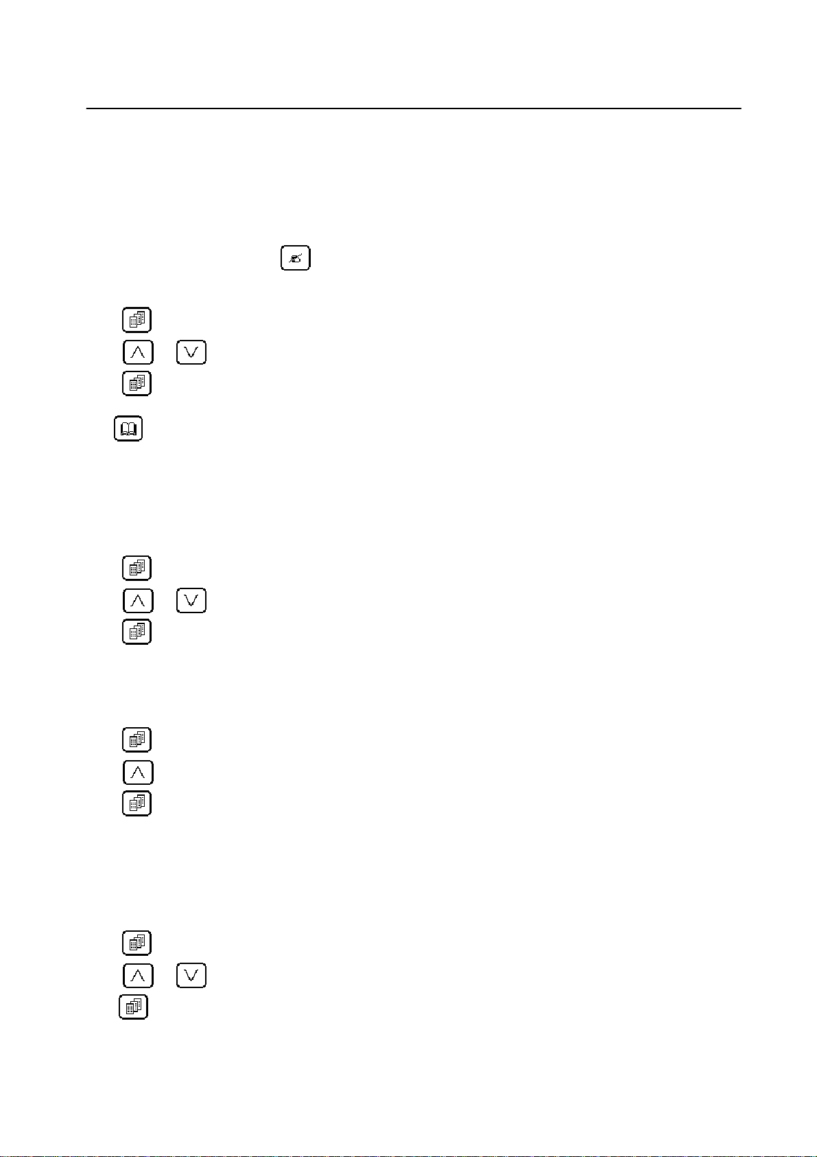
c - ON/OFF
- ESC
d
e
- Confirm
f
g
h
- Change Setting
- Calibration
- Menu
- Store Data
- Increase Symbolized Number
- Backlight Switch
- Re-read Data
1. Switch on
Press key to turn on the gauge. The gauge will consecutively display
- Logo
- Serial No. and software version then the gauge will enter into measuring mode and display
- 0.0mm/0.00mm(0.00IN/0.000IN depending on the last used)
- Velocity rate and selected probe
- Location Lumber
2. Backlight on / off
Press key, the backlight is on. Press key again, the backlight is off.
3. Measurement
There are three ways to go into measuring mode:
- Switch on the gauge;
- Press power key
- Measurement.
escape from MENU;
4. Calibration
When initially switch on the gauge or get an error value instead of 4.00mm (when velocity rate is 5920 m/s) if
take measurement of test block attached on the gauge (which correct value should be 4.00mm) or other
standard test block, the gauge needs to be calibrated simply by pressing
information and operate according to this information, then the gauge will automatically calibrate.
key. The gauge will display same
5. Set-up
Press key, the gauge will display:
1. Measurement
2. Velocity Rate
3. Probe Setting
4. Resolution
5. Memory
6. Limitation
7. Average Measurement

8. Print Out
9. Default
a. Measurement
- No Contents
b. Velocity Rate
b-1. Setting velocity
- Press
- Press
- Press
key into“ Setting velocity ”state
or to change velocity rate
to enter/confirm
b-2. Velocity measurement
- Measuring the sample which thickness is known
- Press
- Press
key into“ Velocity measurement ”state
or to up and down the value of velocity to determine the thickness as the same as the value
of sample that is measured
- Press
key again, the gauge will store the velocity rate automatically.
c. Probe Setting
The gauge provides three types of probe for user.
- Press
- Press
key into “Probe selecting” state
or to select probe.
1= normal probe (PT-08)
2= small diameter probe (PT-06)
3= low frequency probe (ZT-12)
4= High Temperature probe (GT-13)
- Press
d. Resolution
- Press
- Press
1= 0.1 mm
2= 0.01 mm
3= 0.01 IN
4= 0.001 IN
- Press
key to enter/confirm
key into “Resolution” state
or to select resolution and unite.
key to enter/confirm
e. Memory
e-1. Location
The gauge has a memory capacity of 4000 measurements which location can be from 0000 to 3999. After
taking every measurement, press
key to store the value with a location number. You can also select an
initial number for beginning to store the value and the next number will be followed automatically by following
measurements.
- Press
- Press
- Press
key into“ Location ”state
or to select desired number as initial location
key to enter/confirm
If you want to read the stored value in memory,
Press
key to read one by one data according to the above procedure, select desired initial number. Then
the desired group of value can be readable beginning from this initial number.
e-2. Delete Memory
Delete the data in memory which locations are selected.
f. Limitation
- Press
- Press
- Press
key into“ Limitation ”state
or to select desired low limitation and high limitation
key to enter/confirm
When the measuring value is lower or higher than the limit value a sign “L” or “H” will appear on the right top of
LCD.
g. Average Measurement
You can get mean values by 2 to 9 times on TG 200 thickness gauge
- Press
- Press
- Press
key into “ Average ”state
to select desired average times (2 to 9)
key to enter/confirm
When complete measuring once, you must wait about 3 seconds, the gauge will calculate measuring data and
average times will decrease 1 appearing on the right top of LCD. When average times is zero, the gauge will
show the averaged value on LCD.
h. Print Out
If you want to print the stored values, you must determent the initial location number and the end location
number,
- Press
- Press
- Press
key into “Print” state
or to select desired initial and end location number.
key to enter / confirm
The gauge will print the stored value in memory from initial location number to end location number
automatically.

i. Default
When you select “Default” state, the gauge will recover the default parameter.
6. Data print-out (optional)
This procedure is almost like “Print”, but mini-printer replaced by PC.
- Press
- Press
- Press
The stored value in memory will transfer into PC.
key into “Print” state
or to select desired initial and end location number.
key to enter / confirm
7. Technical data
Display unite: 128×32 LCD with backlight
Measuring rate: 2Hz
Velocity rate: 1000 ~ 9999 m/s
0.0393 ~ 0.3936 inch/μs
Measuring range: 0.65 ~ 250.0 mm
0.026 ~ 9.843 inches
Resolution: 0.1 mm 0.01 mm or 0.01 inch 0.001 inch
Tolerance: 0.65 ~ 9.99 mm ±0.04 mm
10 ~ 99.99 mm ±(0.1%+0.04) mm
100 ~ 250 mm ±0.3%
Power supply: two 1.5V AAA dry cells
Size: 61×108×28 mm³ (w×h×d)
Weight: 150g with batteries
Operating temperature: -10 ºC to +50 ºC
Storage temperature: -20 ºC to +60 ºC
Probe types and measuring rang:
Standard probe: PT-08 5.0MHz measuring rang: 0.8 - 200 mm
Miniature probe: PT-06 7.5MHz measuring rang: 0.7 - 50 mm
Lowe frequency probe: ZT-12 2.0MHz measuring rang: 2.0 - 250 mm
High temperature probe: GT-13 5.0MHz measuring rang: 3.0 – 100 mm

8. Appendix
Velocity rate of various materials
Material V (m/s) V (in/us)
Aluminium 6400 0.252
Brass 4700 0.185
Copper 5010 0.197
Glass 5260-6120 0.207-0.241
Lucite 2680 0.105
Nickel 6040 0.237
Nylon 2730 0.103
Polyethylene 1950 0.070
Polystyrene 2350 0.092
Steel 5920 0.233
Stainless Steel 5740 0.226
Titanium 5990 0.237
Water 1490 0.059
Zinc 4210 0.165
NOTE: "This instrument doesn’t have ATEX protection, so it should not be used in potentially explosive
atmospheres (powder, flammable gases)."
 Loading...