

Page 1

© PCE Instruments
Calibrator PCE-RTD 20
User Manual
User manuals in various languages (français,
italiano, español, português, nederlands, türk, polski,
русский, 中文) can be found by using our
product search on: www.pce-instruments.com
Last change: 10 August 2018
v1.0
English
Page 2

© PCE Instruments
Contents
Safety notes ........................................................................................... 1
PCE-TTC 30 Hardware Parts and Accessories .................................. 2
2.1 Unpacking and Inspection ................................................................................................ 2
2.2 Operational Sections and Connections ............................................................................. 3
2.3 Power Options.................................................................................................................. 8
2.4 Battery ............................................................................................................................. 8
Start Up and Basic Operations ............................................................ 9
3.1 Power ON or OFF ............................................................................................................ 9
3.2 User Interface .................................................................................................................10
MENU Layout ....................................................................................... 18
4.1 MENU page ....................................................................................................................18
4.2 MEASURE Page .............................................................................................................18
4.3 SOURCE Page ...............................................................................................................20
4.4 DISPLAY Page................................................................................................................26
4.5 DATA LOGGING Page ....................................................................................................29
4.6 SETTING Page ...............................................................................................................32
Maintenance & Troubleshooting ....................................................... 34
5.1 Common Problems .........................................................................................................34
5.2 Replacing the Battery ......................................................................................................34
Technical Specifications .................................................................... 35
Warranty ............................................................................................... 37
Disposal ............................................................................................... 37
Page 3

© PCE Instruments
1
Safety notes
Please read this manual carefully and completely before you use the device for the first time.
The device may only be used by qualified personnel and repaired by PCE Instruments
personnel. Damage or injuries caused by non-observance of the manual are excluded from our
liability and not covered by our warranty.
• The device must only be used as described in this instruction manual. If used
otherwise, this can cause dangerous situations for the user and damage to the meter.
• The instrument may only be used if the environmental conditions (temperature,
relative humidity, …) are within the ranges stated in the technical specifications. Do
not expose the device to extreme temperatures, direct sunlight, extreme humidity or
moisture.
• Do not expose the device to shocks or strong vibrations.
• The case should only be opened by qualified PCE Instruments personnel.
• Never use the instrument when your hands are wet.
• You must not make any technical changes to the device.
• The appliance should only be cleaned with a damp cloth. Use only pH-neutral
cleaner, no abrasives or solvents.
• The device must only be used with accessories from PCE Instruments or equivalent.
• Before each use, inspect the case for visible damage. If any damage is visible, do not
use the device.
• Do not use the instrument in explosive atmospheres.
• The measurement range as stated in the specifications must not be exceeded under
any circumstances.
• To prevent electrical shocks or damage to the instrument, do not connect more than
30 V between the terminals, or between the terminals and the ground.
• This instrument uses a Lithium-Ion battery pack. To prevent an explosion or fire, do
not short circuit, do not disassemble and keep it safe from damage.
• To prevent battery leakage or heat generation, only use the battery charger in the
temperature range 0 … 45 °C (32 … 113 °F).
• To make sure the display shows the correct data, disconnect the test leads before
you set the power to on or change to another measure or source function.
• To prevent damage to the display, do not use sharp objects on the screen.
• Only sufficiently skilled persons may use the meter. Qualifications from an approved
training establishment may be necessary.
• Follow good engineering practice at all times.
• Non-observance of the safety notes can cause damage to the device and injuries to
the user.
We do not assume liability for printing errors or any other mistakes in this manual.
We expressly point to our general guarantee terms which can be found in our general terms of
business.
If you have any questions please contact PCE Instruments. The contact details can be found at
the end of this manual.
Page 4

© PCE Instruments
2
PCE-TTC 30 Hardware Parts and Accessories
2.1 Unpacking and Inspection
At the factory each new PCE-RTD 20 passes a careful inspection. It should be free of scrapes
and scratches and in proper operation order upon receipt. The receiver should, however,
inspect the unit for any damage that may have occurred during transit. If there are signs of
obvious mechanical damage, package contents are incomplete, or the instrument does not
operate according to specifications, contact the purchasing sales office as soon as possible.
Delivery contents:
1 x RTD Calibrator PCE-RTD 20
3 x Laboratory cables with 2 mm plug
3 x 2 mm laboratory cables with alligator clips
3 x Adapter 2 mm on 4 mm laboratory cable
1 x Mini USB cable
1 x Power supply 5V / 1 A
1 x Carrying bag
1 x User manual
The software can be downloaded here: https://www.pce-instruments.com/english/download-
win_4.htm
If you have to return the instrument to the factory for any reason, use the original packing
whenever possible. Include a detailed description of the reason for the return.
Page 5

© PCE Instruments
3
2.2 Operational Sections and Connections
All sections and connections are presented in detail on the next pages.
Note: Keep in mind that the next picture (as well as all pictures of PCE-RTD 20 in this manual)
has an example configuration of modules. The configuration of your PCE-RTD 20 may vary
significantly from the one in the picture.
1 Terminal Connection for RTD Measure and
Source and EM Measure
2 Keypad Section
3 Color Display
4 USB Connection Slot for PC Communication
and Charging
Page 6

© PCE Instruments
4
2.2.1 Terminal Connections
EM Measure Terminals
Input Terminal for measuring voltage, current and supplying loop power.
EM Measure Terminals
mA
Range: 0.000 … 24.000 mA
Resolution: 0.001 mA
mA(24V)
Range: 0.000 … 24.000 mA
Resolution: 0.001 mA
V
Range: 0.000 … 30.000 V
Resolution: 0.001 V
Current Measurement
The PCE-RTD 20 supports current measurement using either PCE-RTD 20 as the loop power
supply while at the same time measuring the current or simply measuring the current while an
external power supply is used.
The following picture displays the connection for Current Measurement for different mode. And
also different ways of providing the supply power to the loop.
mA Current Measurement
In this mode, the PCE-RTD 20 does not provide any supply voltage. For proper measurement
the external device should capable of providing the voltage supply. If the external device should
not capable, an external Power Supply should be connected in series.
Page 7

© PCE Instruments
5
mA Read Power Current Measurement
In this mode, the PCE-RTD 20 works as Loop Power Supply while at the same time measuring
the current.
Voltage Measurement
The PCE-RTD 20 is capable of voltage Measurement with two voltage measurement ranges.
The following picture displays the connection for Voltage Measurement for different mode.
RTD Terminals
Terminals for measuring and simulating RTD. For RTD/Ω types refer to the specifications.
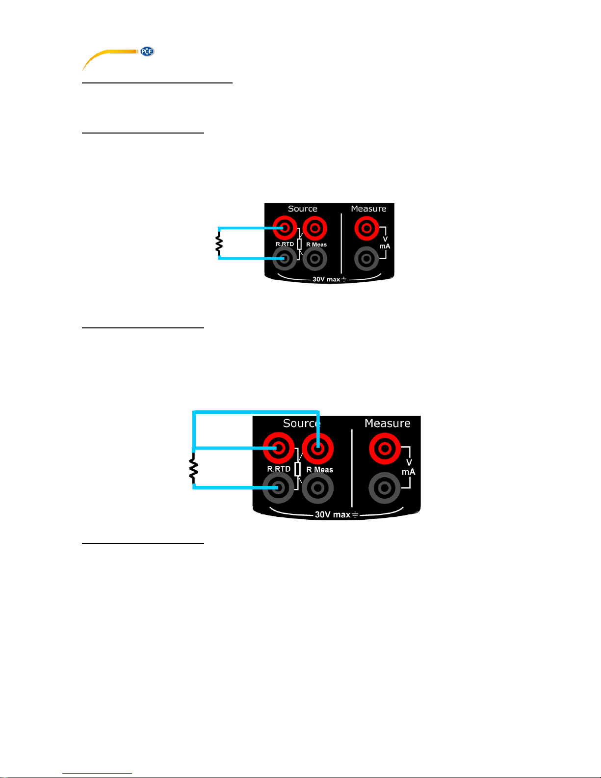
RTD/Resistance simulation
The PCE-RTD 20 is capable of RTD/Resistance generation. The following picture displays the
connection for RTD and Resistance simulation. In RTD simulation RTD 20 mimics an RTD. The
instrument under test generates the current for the RTD measurement.
The PCE-RTD 20 controls the voltage across its terminals so that the resistance (voltage to
Current ratio) corresponds to the simulated temperature. Use of 2-, 3-or 4-wire connection is up
to the receiver instrument. Use only the two leftmost terminals with every wiring option. Connect
the possible third and fourth wire according to the
Requirements of the connected instrument but use only the two left most terminals.
Page 8
© PCE Instruments
6
RTD/Resistance measurement
The PCE-RTD 20 is capable of RTD/Resistance measurement. The following picture displays
the connection for RTD and Resistance measurement.
2-Wire RTD Measurement
Two leftmost terminals are used in 2-wire systems. The PCE-RTD 20 displays the selected
wiring system in run page. PCE-RTD 20 sources current through the resistor and measure the
voltage drop across same terminals. The result is acceptable, if the resistance of the connection
wires is significantly smaller than actual measured resistance.
3-Wire RTD Measurement
The PCE-RTD 20 sources current through the resistor and measure the voltage drop across the
entire current loop and across the upper side connection wire as shown in figure. If both left side
connection wires are identical, the PCE-RTD 20 can compensate for the resistance of the
connection wires.
4-Wire RTD Measurement
The PCE-RTD 20 sources current through the resistor from two left side terminals and measure
the voltage drop across the resistor from the two right side terminals. The 4-wire method gives
the resistance between the terminals of the resistor; it is insensitive to the resistance of the
connection wires.
Page 9

© PCE Instruments
7
2.2.2 KeyPad
The PCE-LOC 20 has six different keys. The key description is given below.
This key has different functionalities in different menus.
These are shown in the bottom left part of the display.
This key has different functionalities in different menus.
These are shown in the bottom left part of the display.
- Scroll down to next parameter
- Decrease value of digit in Editbox
- Scroll down to previous parameter
- Increase value of digit in Editbox
- Enter menu when in Run mode
- Save edited parameter to memory
- Log current reading in memory if device is in Run mode and log mode
is manual
- When not in Run mode, this key is used to enter Run mode
- Press and hold (approx. 2 s) to turn meter on/off
2.2.3 Display
• LCD with a 2.4” color display
• Resolution of 240x320 pixels
• Supporting 262K colors
2.2.4 USB Connection
• The USB connection is located at the top of the PCE-LOC 20. It is a USB mini B-Type
female connector.
• It can be used for PC communication and for charging the device.
• The USB cable supplied with the device is USB A-type male to USB B-type male. It is
used for connecting charger and PC.
Page 10

© PCE Instruments
8
2.2.5 Stand for Table Top Use
• This stand offers the best support for table top use which gives good viewing angle when
the PCE-RTD 20 is placed on a table.
• Procedure to open stand:
is being engraved on the top of the
stand.
You should pull a bit first.
is being engraved on the bottom of the
stand. Now during first pull of above you
can release this lower part easily so that you
can
maneuver the stand as you like.
2.3 Power Options
There are three power options:
• Lithium-Ion battery: All the instrument functions are available with a charged battery.
• 5 V DC charging adaptor: It supplies power to the instrument and charges the battery at the
same time. It charges the battery when the instrument is on or off.
• USB mini Type B connection: This charges the battery when the instrument is off and
increases the battery life when the instrument is on.
2.4 Battery
The Device uses 2300mAh Lithium-Ion battery.
WARNING
• To prevent an explosion or fire, do not short circuit, do not disassemble, and keep it safe
from damage.
• To prevent an explosion or fire, use only the supplied battery, battery charger and USB cable.
• To prevent battery leakage or heat generation, only use the battery charger in the
temperature range 0 … 45 °C (32 … 113 °F).
When you set the power on, the battery symbol at the top of the display shows the charging
status. To get more information on the battery, go to the Battery Info Page in the Setting menu.
Page 11

© PCE Instruments
9
2.4.1 Charging time
Charging method
Charging time (to full capacity)
External Charging Adaptor
≈ 5 hours
Note:
USB mini Type B connector charges the battery when the instrument is off and increases the
battery life when the instrument is on.
2.4.2 Operating Time
Operation
Battery Duration
Continuous operation (measure or source)
>18 hours
Continuous operation (12mA (24V) measure)
> 8 hours
These are typical operating times for a new, fully charged Li-Ion battery pack with these
settings:
• Backlight Intensity set to 5% (Default: 100%)
• Backlight Timeout set to 0 (0=Infinite) (Default: 0)
Power saving options: To get the best battery duration, set a low value for the Backlight
Intensity (40%) and a short Timeout.
The maximum operating time without recharging varies depending on the usage and brightness
setting of the display light. Also the generated output and the usage of the 24 V transmitter
supply affect the maximum operating time.
Notes:
• The PCE-RTD 20’s memory and the internal clock/calendar use a small amount of
power although the calibrator is switched off. Remember to check the capacity of the
batteries from time to time although the PCE-RTD 20 is not in use.
• Do not leave the PCE-RTD 20 without a Battery Pack or an Empty Battery for a long
time. The PCE-RTD 20 may lose its settings if it is left without a support voltage for an
extended period.
Start Up and Basic Operations
3.1 Power ON or OFF
To power ON the instrument, press and release the LOG/Power button until the display comes
on. During the power on sequence, the instrument shows a startup message and then shows
the applicable data.
To power OFF the instrument, press and hold (≈ 2 seconds) the same button again. When the
power is off, the last set of configuration options stays in memory.
Page 12

© PCE Instruments
10
3.2 User Interface
Everytime the PCE-RTD 20 is switched on, the startup message ends in RUN Page.
3 display modes are available in RUN Page.
1. RTD Measure/Source Mode
2. EM Measure Mode
3. RTD Measure/Source + EM Measure Mode
This Display Mode can be selected from MENU→DISPLAY Page.
In case of Dual Mode Display Screen is divided into two parts. Due to that only few additional
info will appear on RUN Page. But Which Information to be shows can be selectable in Display
Mode Menu.
3.2.1 Status Bar
The status bar at the top of the display is visible only in RUN Page. It is divided into five main
sections.
1
Time in HH:MM:SS format
Available in two formats
1. 24 hour (default)
2. 12 hour
This setting is available in Date/Time in Settings Menu
2
Error Code Indicator
This icon is visible if any on-board peripherals like RTC, ADC, DAC, etc. are not
working properly, see chapter 5 Maintenance & Troubleshooting.
The List of error codes available in this device is given below.
Error code
Description
0
Memory corrupted or device unable to read/write it
1
RTC not working properly
2
Device unable to read battery information
3
Measure mode not working
4
Device unable to get source feedback reading
5
Data log memory corrupt
6
Source mode not working
9
More than one error from above list is occurring
Page 13

© PCE Instruments
11
3
USB Connection Status Icon
Icon is visible if USB charging adaptor or USB data cable is connected to the device.
Icon is different for both indications, see below.
USB data cable is connected and communication with PC
is available
USB charging adaptor is connected.
Battery starts charging.
4
Battery Charge Percentage Indicator
Always visible in Run page; battery % is shown in the centre of the icon and the icon
background is filled with green, yellow or red color if battery % is >= 50%, >= 20 and
<20 respectively.
5
Data Logging Enable Status Indicator
Icon is visible if data logging is enabled and will flash when a data log is stored to the
memory
3.2.2 Function key Bar
The function key bar at the bottom of the display is visible all the time. 2 function keys are
available. The meaning of the function keys varies depending on the situation. A blank function
key text means that the function is disabled at the moment.
3.2.3 Display Mode
RTD Mode
Page 14

© PCE Instruments
12
RTD Display Mode
RTD Mode
Shows the Current RTD Mode
RTD Measure Mode
RTD Source Mode
Output Type
Shows the current RTD Type
Source Reading
Shows the RTD Source reading according to RTD Type
STEP/RAMP
Icon
Shows the Icon indicating STEP/RAMP mode. Only applicable if RTD
mode is SOURCE
Manual Step
Rising Ramp
Step UP
Falling Ramp
Step DOWN
Ramp Hold @
0%
Ramp Hold @
100%
Additional Info
Shows the Addition Information according to TC Mode & Additional Info
selected in MENU →DISPLAY→TC terminal
Bar Graph
Horizontal Bar graph according to RTD Percentage Value (0.00% …
100.00%). The value scales according to RTD reading and Input 0%
and 100% value as set in MENU →DISPLAY→RTD terminal Menu
Percentage
Value
The Percentage Value in according to RTD Reading
Wire Select
Shows which RTD configuration is used (2-wire, 3-wire, 4-wire)
Source Display
Mode
Shows which display mode is selected either percentage or actual
Actual Value
When display mode percentage Actual value bar display the actual
source value
Source Info
When RTD is in source mode it shows the excitation current which
comes from the measure device
Page 15

© PCE Instruments
13
EM Measure Mode
Measure Window
Input Type
The Input Type
mA
mA Current Input
mA(24V)
mA Current (Read Power-24V) Input
V
V Voltage Input
Measure Display Mode
The Measure Reading Display Mode
Actual
Displays the Raw Input Value without
any scaling
Percentage
Displays the Percentage Value.
Scaled
Displays the Scaled Value
Measure Reading
The Reading as per the Measure Display Mode
HART Icon
HART Enable Status Icon
This icon will appear if HART is enabled from
MENU →SETTING →HART page. (This icon is visible for
mA(24V) Input Type only. For other Input Types this will
invisible regardless of HART settings)
Bar Graph
Horizontal Bar graph according to Input Percentage Value
(0.00% … 100.00%).
Percentage Value
The Percentage Value in Percentage according to Input
Value.
Tare
The Tare Value Set from MENU→DISPLAY→EM Terminal-
Tare page
Actual Value
The Raw Input Value without any scaling
This will appear only if Main Display in
MENU→DISPLAY→EM Terminal is set to
PERCENTAGE/SCALED.
Min
Displays the minimum value found after a measurement was
started or minimum was reset.
Max
Displays the maximum value found after a measurement was
started or maximum was reset.
Max-Min
Displays the Maximum-Minimum value found after a
measurement was started or Maximum-Minimum was reset.
Cumulative Average
Displays the Cumulative Average value found after a
measurement was started or Cumulative Average was reset.
Page 16

© PCE Instruments
14
RTD + EM Mode
RTD + EM Mode
Output Type
Source Reading
STEP/RAMP Icon
Source window
Refer RTD Display Mode above
Input Type
Measure Reading
HART Icon
Refer EM Display Mode above
3.2.4 Display Operations
There are mainly four types of widgets available in the Device Menu.
i. ListBox
ii. EditBox
iii. CheckBox
iv. RadioButtonBox
The below section will show how to change the value of the different widgets.
Page 17

© PCE Instruments
15
i. ListBox
ListBox are used when there is a limited amount of preset values. You have to select one of the
available options. The list of available options is displayed in the Centre part.
A ListBoxList opens when you press the F1key. Use UP/DOWN key to scroll through the available
options. Select one of the options with the ENTER key.
Example: How to change of Input Type (I/P Type) from mA to V.
This Option is available in MENU→EM SETUP Page
ii. EditBox
EditBox is used where a large range of value can be possible for a parameter.
To edit the value of an EditBox press F1 key. After that EditBox enters into the Edit mode where
F1&F2 keys are works as shifter. User can shift to desired digit and using UP or DOWN key digit
value can be incremented or decremented. The modified value can be saved using MENU/ENT
key.
Page 18

© PCE Instruments
16
The above figure shows the example how to change Input High (100%) Range from 24.000 to
10.000 mA.
There are mainly 2 types of EditBox in this device. In most of the EditBox changing of decimal
point and changing of sign is not allowed. But there are few EditBox, where these are allowed.
Examples Scaled Low (0%) &High (100%) etc.
The below figure shown the example how to change decimal point of the Input Scaled High
(100%) Range.
To change the sign of the value, shift to the sign digit and pressing UP or DOWN key will toggle
the sign.
Page 19

© PCE Instruments
17
iii. CheckBox
CheckBox is used where Binary Value (1/0, True/False) is available for any parameter.
To change the CheckBox status press F1 key. This will enter into the edit mode. In this mode
status can be toggled by pressing F1 key. Press MENU/ENT key to store new status.
iv. RadioButtonBox
RadioButtonBox is used where very few values can be possible and all the available values
need to be visible.
In this device, two types of RadioButtonBox are available. One with 1 value can be selectable
and the other where 1 or 2 values can be selectable at a time.
In RadioButtonBox, the other option can be selected by pressing MENU/ENT key on that option.
When pressing this key the new option will be selected and the other option will be disabled.
Below an example is given, how to change RTD Source Mode from STEP to RAMP.
Page 20

© PCE Instruments
18
MENU Layout
4.1 MENU page
There are mainly six Menus in this device.
To enter into the MENU page press MENU/ENT key and press F2 key to come out from Menu
page.
EM SETUP
Contains Parameters related to EM Measure Mode like Input Type,
Range etc.
RTD SETUP
Contains Parameters related to RTD like RTD Mode, RTD Type
etc.
DISPLAY
Contains Parameters related to different display mode for RUN
page
LOGGING
Contains Parameters related to Data Logging.
Wire Select
Contains Parameters related to wire selection mode
SETTINGS
Contains Parameters related to General Settings of the device like
display, Date/Time, Calibration, Reset, etc.
4.2 MEASURE Page
This Page is appears in RUN →MENU →EM SETUP.
Page 21

© PCE Instruments
19
This page contains parameters related to EM Measure like Input Type, Input Range, Scaling
and Transfer Function. The Description of the Parameters appear on this page is given below.
Parameter Name
Description / Options
I/P Type
(Input Type)
Measure Input Type
Available Options:
mA : 0.000 … 24.000 mA DC
mA(24V) : 0.000 … 24.000 mA DC
V : 0.000 … 30.000 V DC
Input Range
Low (0%)
Low Range for Measure Input
Range:
Default Input Low to Input Range High (100%)
This parameter is enabled if Main Display in MENU →DISPLAY
→EM SETUP is set to Percentage or Scaled.
Input Range
High (100%)
High Range for Measure Input
Range:
Input Range Low(0%)to Default Input High
This parameter is enabled if Main Display in MENU →DISPLAY
→EM SETUP is set to Percentage or Scaled.
Scaled Input
Range
Low (0%)
Scaling Low Range for Measure Input
Range:
-99999 to Scaled Input Range High (100%)
Decimal Point for this EditBox is changeable.
This parameter is enabled if Main Display in MENU →DISPLAY
→EM SETUP is set to Scaled.
Scaled Input
Range
High (100%)
Scaling High Range for Measure Input
Range:
Scaled Input Range Low(0%)to 99999
Decimal Point for this EditBox is changeable.
This parameter is enabled if Main Display in MENU →DISPLAY
→EM SETUP is set to Scaled.
Page 22

© PCE Instruments
20
TF
(Transfer
Function)
Transfer Function for Scaling
Available Options:
Linear
x^2 (x2)
x^(1/2) (√x)
This parameter is enabled if Main Display in MENU →DISPLAY
→EM SETUP is set to Scaled.
4.3 SOURCE Page
This Page is appears in RUN →MENU →RTD SETUP.
This page contains parameters related to RTD like RTD Mode Type, RTD select, Unit, RTD
Source Mode etc. The Description of the Parameters appear on this page is given below.
Parameter Name
Description / Options
RTD Mode
RTD Mode
Available Options:
MEASURE
SOURCE
RTD Select
Select the RTD Type for Measurement / Simulation
Refer section 6 on page 48 for more details on RTD type and its
available range.
RTD Unit
Unit
Measure/Source Reading Unit
Available Options:
Celsius
Fahrenheit
Kelvin
Continuity Test
To test continuity
This Option appear only if RTD Mode is MEASURE.
Page 23

© PCE Instruments
21
Reset Additional
Info
Reset the Additional Info. Like Min, Max of Measure RTD.
This option appear only if RTD Mode is MEASURE.
Source Mode
RTD Source Output Format
This option appear only if RTD Mode is SOURCE.
Available Options:
STEP
RAMP
At a time one can be selectable.
Press F1 key on the one of the option for more settings.
4.3.1 STEP Page
Parameter Name
Description / Options
Low
Starting Value of Step
Enter value according to RTD Display Mode. If display mode is actual
enter value in ohms and if display mode is %, enter value in %.
High
Ending Value of Step
Enter value according to RTD Display Mode. If display mode is actual
enter value in ohms and if display mode is %, enter value in %.
Manual
(Output Type)
Step Manual Mode Selection CheckBox
Ticking this checkbox will enable Step Manual Mode. And Un-ticking
will enable Auto Step Mode.
Step Time (s)
Enter the time for a single step in seconds,
Range:
1 … 9999
This parameter is enabled only for Auto Step Mode (Manual
CheckBox is un-checked)
Page 24

© PCE Instruments
22
Step Definition
Step Definition for the Step function
Available Options:
Temperature (Appear only if RTD Display mode is Actual)
Percentage (Appear only if RTD Display mode is Percentage)
User Defined
Step
Step Value in Temperature/mV/% according to RTD Display Mode
and RTD unit
Only appears if Step Definition is Temperature or Percentage.
Define Steps
User Defined Step value for Manual and Auto Step Mode
This option appears only if Step Definition is User Defined.
Maximum 10 step value can be configured. First enter the no of step
and then define step value in serial order.
Repeat Format
How the stepping should be done.
Available Options:
UP
DOWN
UP/DOWN
DOWN/UP
This parameter is enabled only for Auto Step Mode (Manual
CheckBox is un-checked)
Repeat
Repeat Counts
Defines how many times the steps are repeated
Range:
1 … 9999
This parameter is enabled only for Auto Step Mode (Manual
CheckBox is un-checked)
Page 25

© PCE Instruments
23
Manual Stepping
To Enable Manual Stepping, select Source Type as STEP and Check the Manual CheckBox.
If this mode is enabled, icon will appear in Source Display Window in RUN Page.
Pressing UP or DOWN key in RUN Page will Increment or Decrement Source Value by Step
specified in STEP Page.
In RUN Page, Source Value can directly change by Pressing F1 key (EDIT) and modifying value
like in EditBox. And STEP Setting can be accessed directly by F2 key (SETTING).
Auto Stepping
To Enable Auto Stepping, select Source Type as STEP and Un-Check the Manual CheckBox.
If this mode is enabled, (Step UP) or (Step Down) icon will appear in Source Display
Window in RUN Page and F1 and F2 Button change to START and SETTING respectively.
Automated Step can be started by Pressing F1 key (START). After that F1 and F2 key will
change to PAUSE and STOP respectively. So by pressing F1 and F2 key running STEP can be
PAUSE or STOP at any time in RUN Page.
STEP Setting can be accessed directly by F2 key (SETTING).
Note: While STEP is running, STEP settings are not accessible and Source Page Parameter
settings can’t be changed. Stop STEP before changing any settings.
4.3.2 RAMP Page
Parameter Name
Description / Options
Low
Starting Value of Ramp
Enter value according to RTD Display Mode. If display mode is actual
enter value in ohms and if display mode is %, enter value in %.
High
Ending Value of Ramp
Enter value according to RTD Display Mode. If display mode is actual
enter value in ohms and if display mode is %, enter value in %.
Hold@0%(s)
Time to wait at Low (0%) level in second
This parameter is used for Repeat Format UP/DOWN or DOWN/UP.
Range:
0 … 9999
Page 26

© PCE Instruments
24
Rise Time (s)
Time to Increase from Low to High Level
Range:
1 … 9999
Hold@100%(s)
Time to wait at High (100%) level in second
This parameter is use for Repeat Format UP/DOWN or DOWN/UP.
Range:
0 … 9999
Fall Time (s)
Time to decrease from High to Low Level
Range:
1 … 9999
Repeat Format
How the Ramp should be done
Available Options:
UP
DOWN
UP/DOWN
DOWN/UP
Repeat
Repeat Counts
Defines how many times the steps are repeated
Range:
1 … 9999
Starting the RAMP
To Enable Ramp, select Source Type as RAMP.
If this mode is enabled, (Rising Ramp) or (Falling Ramp) or (Ramp Hold @
100%) or (Ramp Hold @ 0%) icon will appear in Source Display Window
according to current RAMP mode in RUN Page and F1 and F2 Button change to START and
SETTING respectively.
RAMP can be started by Pressing F1 key (START). After that F1 and F2 key will change to
PAUSE and STOP respectively. So by pressing F1 and F2 key running RAMP can be PAUSE
or STOP at any time in RUN Page.
Page 27

© PCE Instruments
25
4.3.3 Continuity Test
Parameter Name
Description / Options
Continuity
Feature
Continuity Feature Selection RadioButtonBox
Selecting RadioButtonBox will enable continuity feature for RTD
Measure Mode.
Threshold
Enter the threshold value of resistance up to which continuity test is
applied.
Range:
0 … 100
When Testing Continuity Beep sounds and continuity symbol appear on run page as shown in
below figure. When resistance between the Ω Measure terminal is less than 25Ω (or defined in
threshold parameter). To test the continuity remove power from the circuit to be tested.
Page 28

© PCE Instruments
26
4.4 DISPLAY Page
This Page is appears in RUN →MENU →DISPLAY.
There is mainly three RUN Display Mode possible in this device. And this mode can be selected
from the above Page. What information to be shown in each RUN Display Mode can be defined
by this page.
In this page there is one RadioButtonBox. At a time one or two option can be selected. The
possible combinations are given below.
1
EM (Electrical Measurement) Only
2
RTD (Measure/Source) Only
3
EM + RTD
4.4.1 EM Display Settings
This Page is appears in RUN →MENU →DISPLAY →EM Terminal.
Page 29
© PCE Instruments
27
Parameter
Name
Description / Options
Main Display
Select which Reading to be display as a Main Reading (Reading
Displays in Box in RUN Page).
Available Options:
Actual
Display the Actual Input Value
Percentage
Display the Percentage Value of the Input
The Value depends on Input Range. These
settings are available from MENU →EM SETUP.
Scaled
Display the Scaled Value of the Input
The Scale Value depends on Input Range, Input
Scaled Range and Transfer Function. These
settings are available from MENU →EM SETUP.
Filter(sec)
1st Order IIR Low Pass Filter for Input Reading
Filter is useful when a measurement signal contains unwanted noise.
Range:
0.0 … 60.0 sec
Tare(unit)
The Tare value is subtracted from the reading of the measured value.
Here unit is changed according to current Input Type and Measure
Display Mode.
Range:
In accordance with Input Range and Measure Display Mode.
Note: Beware of the problems that may result in not seeing the
true measurement value.
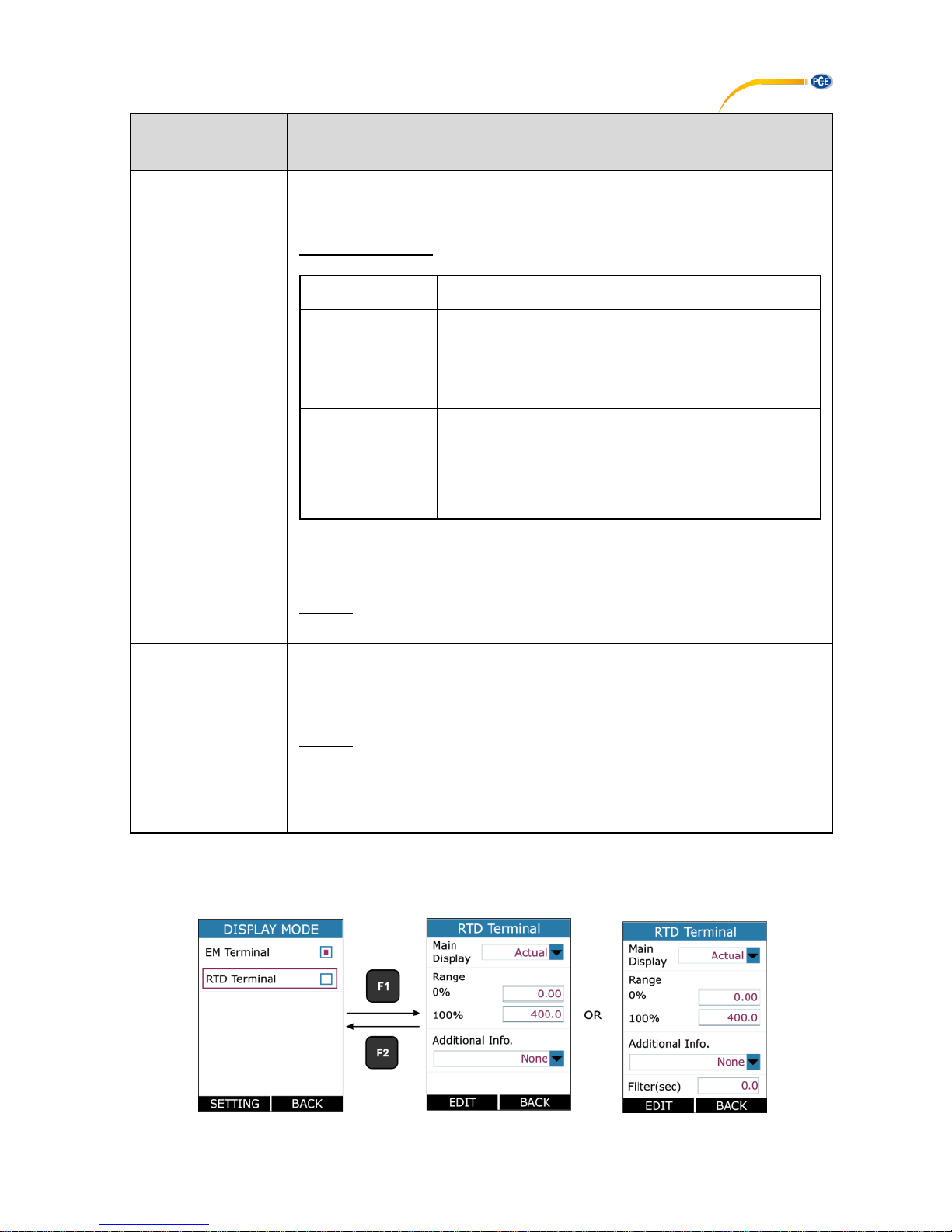
4.4.2 RTD Display Settings
This Page is appears in RUN →MENU →DISPLAY →RTD Terminal.
Page 30

© PCE Instruments
28
Parameter Name
Description / Options
Main Display
Select which Reading to be display as a Main Reading (Reading
Displays in Box in RUN Page).
Available Options:
Actual
Display the Actual RTD/Resistance Value
Percentage
Display the Percentage Value of
RTD/Resistance according to value set in 0%
and 100%.
0%
Low Value in Temperature/ohms for (0-100%) scaling
100%
High Value in Temperature/ohms for (0-100%) scaling
Additional Info.1
Choose which information to be shown as RTD Mode Additional
Information on RUN Page.
Available Options for RTD Measure Mode:
Options
Icon
Description
None
-
No info is visible.
Actual Value
Shows the Actual RTD
Temperature/ohms value without
any scaling.
This option is available only if RTD
Display Mode is Percentage.
Maximum
Shows the Maximum measured
reading from the time when info last
reset.
Minimum
Shows the Minimum measured
reading from the time when info last
reset.
Min & Max
-
Shows the Minimum and Maximum
value both together. This option
available only for RTD Display
mode.
Page 31

© PCE Instruments
29
Available Options for RTD Source Mode:
Options
Icon
Description
None
-
No info is visible.
Actual Value
Shows the Actual RTD
Temperature/ohms value without
any scaling.
This option is available only if RTD
Display Mode is Percentage.
Excitation
Current
Shows the current which is
sourced by instrument under test.
Filter(sec)
1st Order IIR Low Pass Filter for RTD Measure Reading.
This option is available only for RTD mode is Measure.
Filter is useful when a measurement signal contains unwanted noise.
Range:
0.0 … 60.0 sec
4.5 DATA LOGGING Page
This section gives examples of how to log Readings with time and date over a set time period or
on a key press. Logged data is stored in a user defined file in internal memory.
This Page is appears in RUN →MENU →LOGGING.
Parameter Name
Description / Options
Trigger
Data Logging Trigger Mode Selection
Available Options:
Key Press
Log Data on pressing from RUN key Page.
Periodic
Log Data periodically at every Sampling Rate for
total time specified by Logging Time.
Page 32

© PCE Instruments
30
Mode
Data Mode Selection for Logging
Available Options:
EM
Log only EM Measure Readings.
RTD
Log only RTD Terminal Readings.
EM+RTD
Log EM MeasureandRTD Terminal both Readings.
This parameter is enabled only for Periodic Trigger.
Save Method
Reading Type selection for Logging
Available Options:
Instant
Min
Max
Average
All
This parameter is enabled only for Periodic Trigger.
Sampling
Rate(s)
Sampling Rate for Periodic Data Logging in seconds
Range:
1 … 9999
This parameter is enabled only for Periodic Trigger.
Logging Time
(HH:MM:SS)
Total Logging Time in HH:MM:SS Format for Periodic Logging.
This parameter is enabled only for Periodic Trigger.
File No.
File Number.
Range:
1 … 25
This parameter is enabled only for Periodic Trigger.
File Info.
Shows the information of stored files. This information contains
Logging Start Time & Date and No of Samples stored in the file.
File Delete
Delete stored file.
START
LOGGING
Press F1 key while selecting this button to start the Logging.
Page 33

© PCE Instruments
31
Notes:
• Maximum no. of readings that can be stored in
Logging Mode
Max. Reading
Periodic
150000
Key Press
528
• In Periodic mode, changing of any Measure or Source parameter is not allowed. So
while Periodic Logging is Running, the user can’t enter into MEASURE, SOURCE and
DISPLAY menu. But in Key Press Logging mode, there is no restriction.
• In Periodic Mode, if an error message like “Not Sufficient Memory” comes while starting
the Logging, try reducing the logging time or increase the sampling period or try deleting
some existing files.
• In Key Press Mode, if the no. of samples reaches its maximum limit that is 484, the next
sample will start from the first overwriting the memory.
• While Logging is running, entering into the LOGGING menu shows below page.
for Periodic Mode for Key Press Mode
• For Periodic Mode, this page contains information of Number of Samples Taken
and Time Remaining for Logging in HH:MM: SS.
• Both Periodic and Key Press logging can be stop manually by pressing F1 key on
STOP LOGGING Button. For Periodic Mode, Logging will automatically stopped
when defined log time ends and a message “LOGGING DONE” pops up.
Transferring the Results to a Personal Computer:
A 32-bit Windows® software called mCAL+.exe can be downloaded here: https://www.pce-
instruments.com/english/download-win_4.htm. Start this software just as any other Windows®
software.
All communication between the PC and PCE-LOC 20 is initiated from mCAL+.exe.
More information on the software can be found in the separate software manual.
Page 34

© PCE Instruments
32
4.6 SETTING Page
This Page is appears in RUN →MENU →SETTING.
All the available Settings Options are given below.
i. HART
ii. Display
iii. Date/Time
iv. Calibration
v. Battery Info.
vi. Set Password
vii. Factory Reset
viii. About Us
Press F1 key to Enter into the settings of any option. Description of all settings given below.
4.6.1 HART Settings
Select YES to add a Series resistor (250Ω) into the mA
circuit. You can then use this instrument together with a
HART® communicator to set up and calibrate HART®
devices. This option is applicable for mA(24V) Read Power
Input Type Only.
Page 35

© PCE Instruments
33
4.6.2 Display Settings
Display
Intensity
Display Brightness Settings.
Range:
5 to 100
Display Off
Time
Standby Time in second after which
display will turn Off. To turn the
display off press any key.
Range:
0 to 9999 sec
Setting 0 will disable this feature.
That means display will never turn off
automatically.
4.6.3 Date/Time Settings
To set the Time + Date of the device.
2 date formats are supported in this device: DD/MM/YY
and MM/DD/YY. This is useful only in Data Logging, to
decide in which format the Date is to be stored.
2 time formats are supported in this device: 24 Hour and
12 Hour. This is to select in which format the time should
be displayed on Run page and time to be stored in Data
Logging.
AM/PM selection is enabled only for 12 Hour Time Format.
4.6.4 Calibration
The instrument is factory calibrated for the specified range, but due to long term drift of
components, re-calibration may be necessary in some cases. For calibrating the instrument, a
reliable source is required. This source should be at least ten times accurate compared to the
range of the instrument.
Note: PCE Instruments can provide a calibration service that is traceable to international
standards.
We recommend that you return the instrument to the manufacturer or an approved service agent
for calibration. If you use an alternative calibration facility, make sure that it uses these standards.
Page 36

© PCE Instruments
34
4.6.5 Battery Info
This page shows the basic battery Information.
• Battery Level (Percentage)
• Battery Voltage (in mV)
• Current (in mA)
• Battery Status
• Time to Full (in min)
• Time to Empty (in min)
4.6.6 About Calibrator
This Page illustrates the Connection diagrams for valid connections to this device.
Maintenance & Troubleshooting
5.1 Common Problems
Problem
Possible Causes
Device Not Starting Up
• Battery Discharged
• Battery Connection Loose
Reading Fluctuation/
Reading OPEN
• Wrong / Loose Connections
Error Code on status bar
• One of the peripheral not working properly.
(Solution: Restart the Device if still error code
showing contact factory)
Calibration Out
• Distortion in due to external noise connection
(Solution: Check connection. If still out contact
factory or Recalibrate Device in authorized cal-lab.)
Battery Not Charging
• Battery Connection Loose
• Battery Dead
5.2 Replacing the Battery
Page 37

© PCE Instruments
35
Technical Specifications
Measuring range
Resolution
Accuracy (by Mw.)
Measuring parameter voltage DC V
0 ... 30V
0.001V
± 0.02% v.Mw. + 2 Dgt
Measuring parameter current DC mA
0 ... 24-mA
0.001-mA
± 0.02% v.Mw. + 2 Dgt
Measurement parameter resistance
0 ... 400 Ω
0.01 Ω
± 0.02% v.Mw. + 0.01Ω
Pt10 ... Pt1000
-200 ... 200°C / -328 ...
392°F
Pt10 ... Pt400: 0.01°C /
0.018°F
± 0.2°C / 0.36°F
200 ... 600°C / 392 ...
1112°F
Pt500 ... Pt100: 0.1°C /
0.18°F
± 0.3°C / 0.54°F
600 ... 850°C / 1112 ...
1562°F
± 0.1°C / 0.18°F
Ni100
-60 ... 180°C / -76 ... 356°F
0.01°C / 0.018°F
± 0.1°C / 0.18°F
Ni120
-80 ... 260°C / - 112 ... 500°F
± 0.1°C / 0.18°F
Cu10
-200 ... 260°C / -328 ...
500°F
± 0.2°C / 0.36°F
*In 4-wire measuring mode, a resolution of up to 0.01 Ω in the range 0 ... 1600 Ω is possible.
The specified accuracy applies to the 4-wire measuring mode. With 3-wire measurement,
measurement inaccuracy increases by 1°C / 1.8°F (Pt10 / Cu10), 0.6°C / 1.08°F (Pt50 /
Cu50) and 0.4°C / 0.72°F (remaining types).
Simulation area
Resolution
Accuracy*
Simulation parameter resistance
0 ... 400 Ω
0.01 Ω
± 0.02% v.Mw. + 0.01Ω
400 ... 4000 Ω
0.1 Ω
± 0.02% v.Mw. + 0.015Ω
Simulation parameters Pt10 ... Pt1000
-200 ... 200°C / -328 ...
392°F
Pt10 ... Pt400: 0.01
± 0.15°C / 0.27°F
200 ... 600°C / 392 ...
1112°F
Pt500 ... Pt100: 0.1
± 0.25°C / 0.45°F
600 ... 850°C / 1112 ...
1562°F
± 0.15°C / 0.27°F
Simulation parameter Ni100
-60 ... 180°C
0.01°C / 0.018°F
± 0.15°C / 0.27°F
Simulation parameter Ni120
-80 ... 260°C
0.01°C / 0.018°F
± 0.15°C / 0.27°F
Simulation parameter Cu10
-200 ... 260°C
0.01°C / 0.018°F
± 0.8°C / 1.4°F
*Accuracy is valid at a current of> 0.2-mA or> 0.4-mA.
Compatible RTD sensor
Pt10 (385), Pt50 (385), Pt100 (385), Pt200 (385), Pt400
(385), Pt500 (385), Pt1000 (385), Pt10 (3926)
Ni100 (672), Ni (618), Ni120 (672), Cu10 (427), Cu50 (427),
Cu100 (427)
Page 38

© PCE Instruments
36
General Specifications PCE-RTD 20
Display modes
Measurement: mA / V / Ω / RTD
Simulation: Ω / RTD
Temperature units
° C / ° F / K
Current of RTD
measurement
About 300 μA
Maximum current
simulation
3-mA (0 ... 650 Ω)
I < 2V / Rsim (650 ... 4000 Ω)
Maximum input
voltage
30V DC
Temperature
coefficient
<30 ppm
Input impedance
Voltage measurement:> 1 MΩ
Current measurement: 10 Ω
Response time
<100 ms
Refresh rate display
10 Hz
Data storage
Internal memory
150000 readings
Interface
USB 2.0
Display
2.4" TFT LCD
240 x 320 pixels
LED illuminated
Output voltage
current loop
24V DC / 24-mA
HART mA loop
resistance
250 Ω ± 20%
Special features
Step and ramp function
Automatic and manual
mode √x, x2: For the measuring function
Continuity test
Adjustable threshold up to 100 Ω
Power supply
3.7V / 2300-mAh Li-ion battery
Charging time
About 5 h
Power adapter
Input: 100 ... 240V AC / 50/60 Hz
Output: 5V / 1 A DC
Battery life
Approx. 15 h: Simulation and measurement with low LCD
illumination
Approx. 8 h: Measurement with low LCD illumination
Dimensions
162 x 82 x 40 mm / 6.4 x 3.2 x 1.6 in
Weight
About 300 g / < 1 lb
Degree of protection
IP20
Operating conditions
Battery operation: 0 ... 55°C / 32 ... 131°F, 30 ... 90% RH Mains
operation: 0 ... 45°C / 32 ... 113°F, 30 ... 90% RH
Storage conditions
-20 .. 60°C / -4 ... 140°F, 30 ... 90% rh non-condensing
Heating time
About 15 minutes
Page 39

© PCE Instruments
37
Warranty
You can read our warranty terms in our General Business Terms which you can find here:
https://www.pce-instruments.com/english/terms.
Disposal
For the disposal of batteries in the EU, the 2006/66/EC directive of the European Parliament
applies. Due to the contained pollutants, batteries must not be disposed of as household waste.
They must be given to collection points designed for that purpose.
In order to comply with the EU directive 2012/19/EU we take our devices back. We either re-use
them or give them to a recycling company which disposes of the devices in line with law.
For countries outside the EU, batteries and devices should be disposed of in accordance with
your local waste regulations.
If you have any questions, please contact PCE Instruments.
Page 40

© PCE Instruments
38
PCE Instruments contact information
Germany France Spain
PCE Deutschland GmbH PCE Instruments France EURL PCE Ibérica S.L.
Im Langel 4 23, rue de Strasbourg Calle Mayor, 53
D-59872 Meschede 67250 Soultz-Sous-Forets 02500 Tobarra (Albacete)
Deutschland France España
Tel.: +49 (0) 2903 976 99 0 Téléphone: +33 (0) 972 3537 17 Tel. : +34 967 543 548
Fax: +49 (0) 2903 976 99 29 Numéro de fax: +33 (0) 972 3537 18 Fax: +34 967 543 542
info@pce-instruments.com info@pce-france.fr info@pce-iberica.es
www.pce-instruments.com/deutsch www.pce-instruments.com/french www.pce-instruments.com/espanol
United States of America United Kingdom Italy
PCE Americas Inc. PCE Instruments UK Ltd PCE Italia s.r.l.
711 Commerce Way suite 8 Unit 11 Southpoint Business Park Via Pesciatina 878 / B-Interno 6
Jupiter / Palm Beach Ensign Way, Southampton 55010 Loc. Gragnano
33458 FL Hampshire Capannori (Lucca)
USA United Kingdom, SO31 4RF Italia
Tel: +1 (561) 320-9162 Tel: +44 (0) 2380 98703 0 Telefono: +39 0583 975 114
Fax: +1 (561) 320-9176 Fax: +44 (0) 2380 98703 9 Fax: +39 0583 974 824
info@pce-americas.com info@industrial-needs.com info@pce-italia.it
www.pce-instruments.com/us www.pce-instruments.com/english www.pce-instruments.com/italiano
The Netherlands Chile Hong Kong
PCE Brookhuis B.V. PCE Instruments Chile S.A. PCE Instruments HK Ltd.
Institutenweg 15 RUT: 76.154.057-2 Unit J, 21/F., COS Centre
7521 PH Enschede Santos Dumont 738, local 4 56 Tsun Yip Street
Nederland Comuna de Recoleta, Santiago, Chile Kwun Tong
Telefoon: +31 (0)53 737 01 92 Tel. : +56 2 24053238 Kowloon, Hong Kong
Fax: +31 53 430 36 46 Fax: +56 2 2873 3777 Tel: +852-301-84912
info@pcebenelux.nl info@pce-instruments.cl jyi@pce-instruments.com
www.pce-instruments.com/dutch www.pce-instruments.com/chile www.pce-instruments.cn
China
Turkey
PCE (Beijing) Technology Co.,Ltd PCE Teknik Cihazları Ltd.Şti.
1519 Room, 6 Building Halkalı Merkez Mah.
Men Tou Gou Xin Cheng, Pehlivan Sok. No.6/C
Men Tou Gou District 34303 Küçükçekmece - İstanbul
102300 Beijing Türkiye
China Tel: 0212 471 11 47
Tel: +86 (10) 8893 9660 Faks: 0212 705 53 93
info@pce-instruments.cn info@pce-cihazlari.com.tr
www.pce-instruments.cn www.pce-instruments.com/turkish
 Loading...