

Page 1
© PCE Instruments
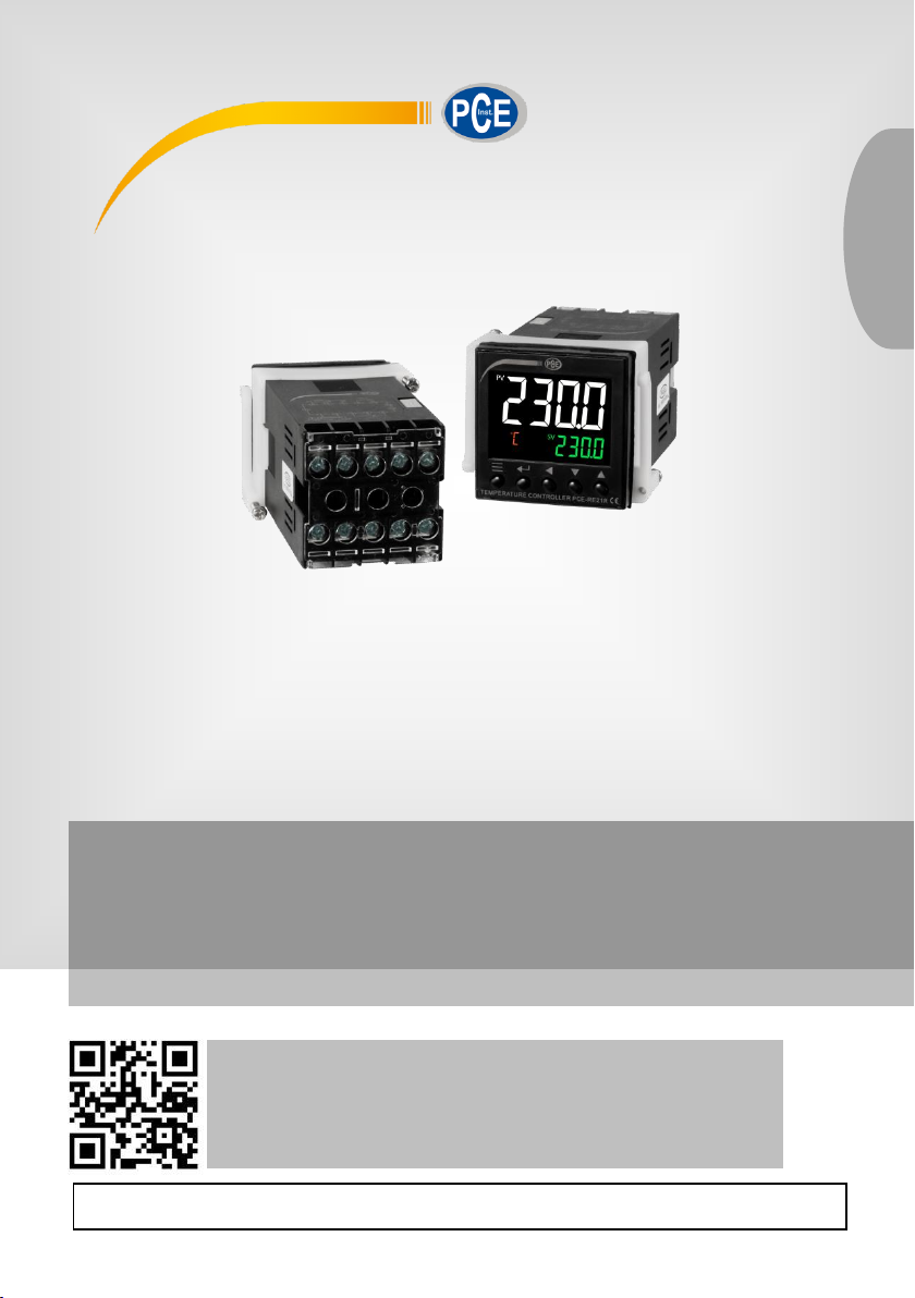
Temperature Controller PCE-RE21R, PCE-RE21S, PCE-RE21T
User Manual
User manuals in various languages (français,
italiano, español, português, nederlands, türk, polski,
русский, 中文) can be found by using our
product search on: www.pce-instruments.com
Last change: 1 October 2019
v1.0
English
Page 2

© PCE Instruments
Contents
1 Safety notes ........................................................................................... 1
2 Main features ......................................................................................... 2
3 Technical parameters ........................................................................... 2
4 Front Panel Descrition .......................................................................... 3
5 Size ......................................................................................................... 3
6 Display the status and basic operation .............................................. 4
6.1 System parameter setting................................................................................................. 4
6.2 Set value setting ............................................................................................................... 5
6.3 “At”PID parameter auto-tuning.......................................................................................... 5
7 Parameter list and function .................................................................. 5
7.1 Field parameters .............................................................................................................. 5
7.2 Field parameter ................................................................................................................ 6
8 Default settings ..................................................................................... 7
9 Wiring diagram ...................................................................................... 8
10 Note ........................................................................................................ 8
11 Warranty ................................................................................................. 9
12 Disposal ................................................................................................. 9
Page 3

© PCE Instruments
1
1 Safety notes
Please read this manual carefully and completely before you use the device for the first time. The
device may only be used by qualified personnel and repaired by PCE Instruments personnel.
Damage or injuries caused by non-observance of the manual are excluded from our liability and
not covered by our warranty.
• The device must only be used as described in this instruction manual. If used otherwise,
this can cause dangerous situations for the user and damage to the meter.
• The instrument may only be used if the environmental conditions (temperature, relative
humidity, …) are within the ranges stated in the technical specifications. Do not expose
the device to extreme temperatures, direct sunlight, extreme humidity or moisture.
• Do not expose the device to shocks or strong vibrations.
• The case should only be opened by qualified PCE Instruments personnel.
• Never use the instrument when your hands are wet.
• You must not make any technical changes to the device.
• The appliance should only be cleaned with a damp cloth. Use only pH-neutral cleaner,
no abrasives or solvents.
• The device must only be used with accessories from PCE Instruments or equivalent.
• Before each use, inspect the case for visible damage. If any damage is visible, do not
use the device.
• Do not use the instrument in explosive atmospheres.
• The measurement range as stated in the specifications must not be exceeded under
any circumstances.
• Non-observance of the safety notes can cause damage to the device and injuries to
the user.
We do not assume liability for printing errors or any other mistakes in this manual.
We expressly point to our general guarantee terms which can be found in our general terms of
business.
If you have any questions please contact PCE Instruments. The contact details can be found at
the end of this manual.
Page 4
© PCE Instruments
2
2 Main features
- White large characters color LCD display and new higher contrast LCD with
greatly improved visibility.
- Easy to Use, from Model Selection to Setup and Operation.
- The External waterproof sealing ring and the Internal waterproof sealing ring make
the instrument reach the good waterproof performance.
- Plastic Handle waterproof type key, is a hard surface that won't scuff, Operation
feel clear and smooth.
- Input type: K, E, J, N thermocouples and Pt100 platinum resistance freely
programmable.
- Use digital calibration technology for input Measurement accuracy:0.3%FS,
maximum resolution is 0.1℃.
- Use advanced artificial intelligent control algorithm, no overshoot and with the
function of auto tuning (AT) and self-adaptation.
- With worldwide power supply of AC/DC100-240V or DC12-24V.
3 Technical parameters
Power supply voltage
AC/DC 100~240V or DC 12-24V (-15%, +10% / 50-60HZ)
Operating voltage range
85% to 110% of rated supply voltage
Power consumption
Approx. 5.2 VA at 100 to 240V AC,
Approx. 3 VA at 12 to 24 VDC
Measurement accuracy
0.3% FS ±1 measurement unit
Input type and
Measuring range
K (-50~+1300°C),
E (0~800°C),
J (0~1000°C),
N (0~1300°C),
Pt100 (-200~+600°C)
Decimal point
0,0.0
Response time
≤ 0.5 sec. (when digital filter parameter InF=0)
Control mode
one-stop regulating, Intelligent Fuzzy PID algorithm
Control
output
PCE-RE21R
Relay output 3A / 250V AC; 5A / 30V DC
PCE-RE21S
SSR output 12V DC / 50mA (Used to drive SSR)
PCE-RE21T
Triac output NO TRIAC 1A / 250V AC
Electromagnetic
compatibility (EMC)
IEC61000-4-4 (Electrical Fast Transient Burst) ±4KV / 5KHz;
IEC61000-4-5 (Surge), 4KV
Isolation
withstanding voltage
Between power relay contact or signal terminals ≥ 2300V DC;
between isolated electroweak terminals ≥ 600V
Operating Ambient
Temperature: 0~60 °C; Humidity ≤ 90% RH
Page 5
© PCE Instruments
3
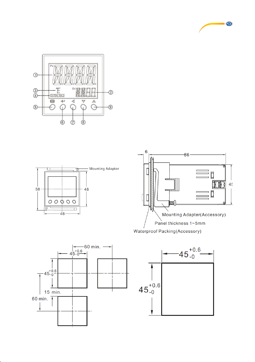
4 Front Panel Description
1. No. 1 display, PV or specified parameter
2. No. 2 display, SP or specified parameter value
3. Temperature unit: °C/°F
4. Operation indicators:
OUT indicators, AL 1 indicator, AL2 indicators
5. Setup key: For accessing parameter table and
conforming parameter modification
6. Enter key: For confirm and change to another
Parameter
7. Data shift key
8. Data decrease key
9. Data decrease key
5 Size
Multiple install cutouts
Single install cutout
Page 6
© PCE Instruments
4
6 Display the status and basic operation
6.1 System parameter setting
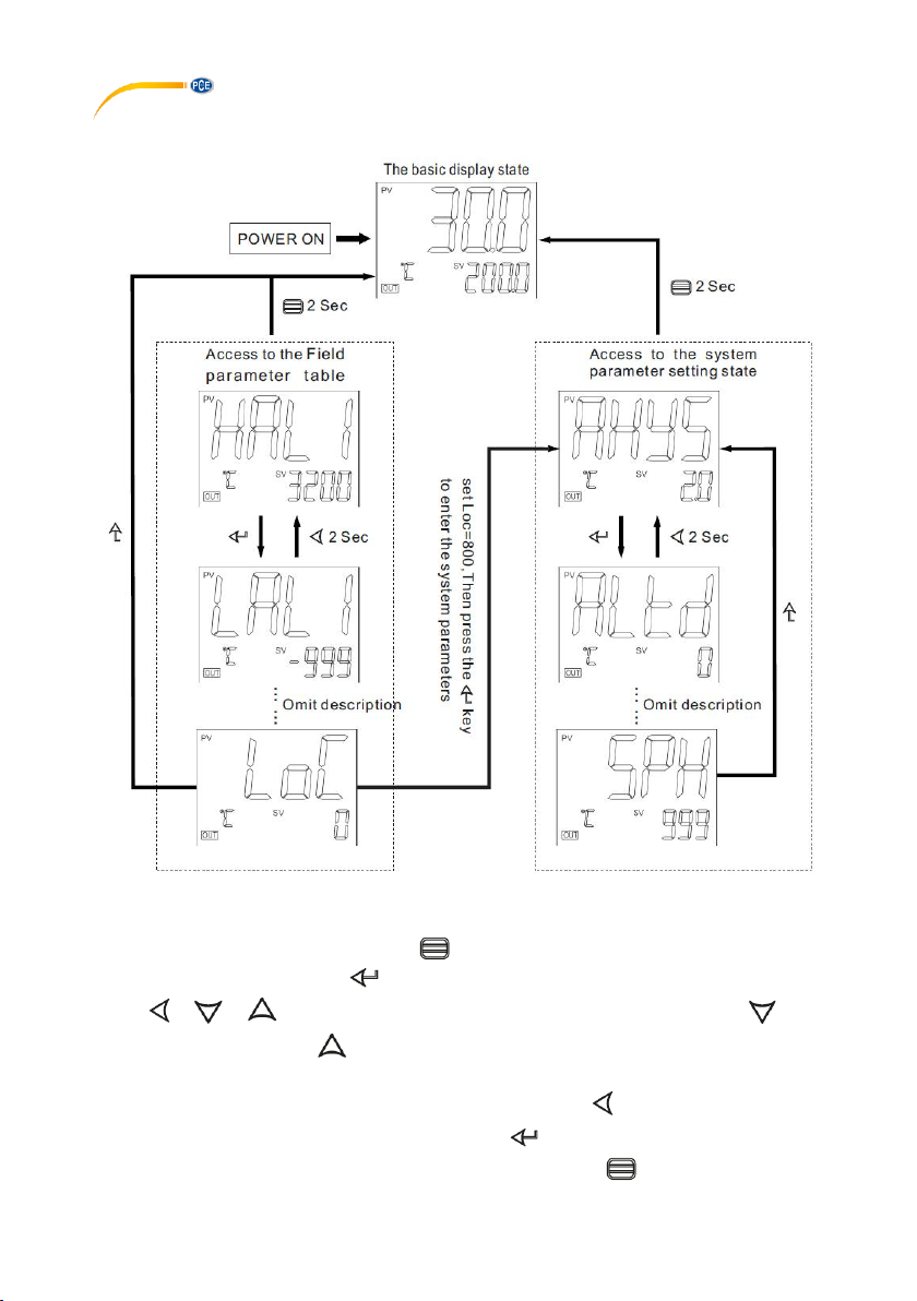
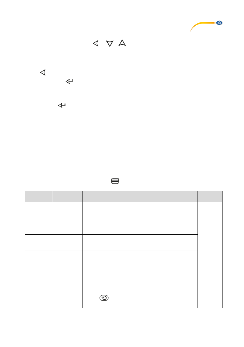
In the basic display state, press and hold key for 2 seconds. Enter the field parameters, set
the LOC = 800. Then press the button to confirm and enter the system parameter setting
state. , , key can directly modify the parameter values. Press the key to
reducing the data, press the to increase the data. Waiting to modify the value of the decimal
point will flash (like a cursor). Press key and hold, you can quickly increase / decrease in value,
and the speed will be automatically accelerated. Also press the key to move to modify the
data location (cursor), the operation is more efficient. key can be stored to modify
parameter values and display the next parameter, press and hold key 2 seconds, and can
return to the previous parameter; can immediately exit the parameter setting state.
Page 7
© PCE Instruments
5
6.2 Set value setting
In the basic display state, press , , key can directly modify the given value.
6.3 “At”PID parameter auto-tuning
Press and hold for 2 seconds, the At parameter appears,"At" parameter "OFF" is set to "ON"
and then press the key to confirm instrument can start the implementation of the autotuning
Given function, the instrument in the basic display state display will flash the word "At",
the instrument after 2 oscillation cycle ON-OFF control can automatically calculate the PID
parameters. If you want to advance to give up auto-tuning , "At" parameter “ON” is set to “OFF”
and then press key to confirm.
Given tuning parameter values obtained are not identical, to perform auto-tuning function,
should be first given value set in the most commonly used value or middle value, if the system
is good insulation properties of the furnace, the given value should be set in the system uses
the maximum, and then Execute the start of the operation of auto-tuning function. Reasons to
learn, auto-tuning after the initial use, the effect may not be the best, you need a period of time
(usually the same time auto-tuning control) before they can get the best results.
7 Parameter list and function
7.1 Field parameters
In the basic display state, press and hold key 2 seconds, enter the field parameters,
Parameter
code
Meaning of
parameters
Explain
Setting
range
HAL1
AL1 high
limit alarm
value
“HAL1” is the absolute value alarm or deviation value
alarm, by “ALtd” parameter definition. When the value
set to Max. will disable this function. (3200)
-999~
+32000
LAL1
AL1 low
limit alarm
value
“LAL1” is the absolute value alarm or deviation value
alarm, by “ALtd” parameter definition. When the value
set to Min. will disable this function. (-999)
HAL2
AL2 high
limit alarm
value
“HAL1” is the absolute value alarm or deviation value
alarm, by “ALtd” parameter definition. When the value
set to Max. will disable this function. (3200)
LAL2
AL2 low
limit alarm
value
“LAL1” is the absolute value alarm or deviation value
alarm, by “ALtd” parameter definition. When the value
set to Min. will disable this function. (-999)
Srun
running
state
run:Run control state StoP:Stop state, No.2 display
flashing display "StoP".
run
StoP
LOC
Parameter
lock
LOC<9000, will automatically for 0, allowed to modify
the SV Set Value. LOC≥9000, are not allowed to
modify the SV Set Value. Set the LOC = 800, then
press key to confirm, can enter the following
system parameters.
0~9999
Page 8

© PCE Instruments
6
7.2 Field parameter
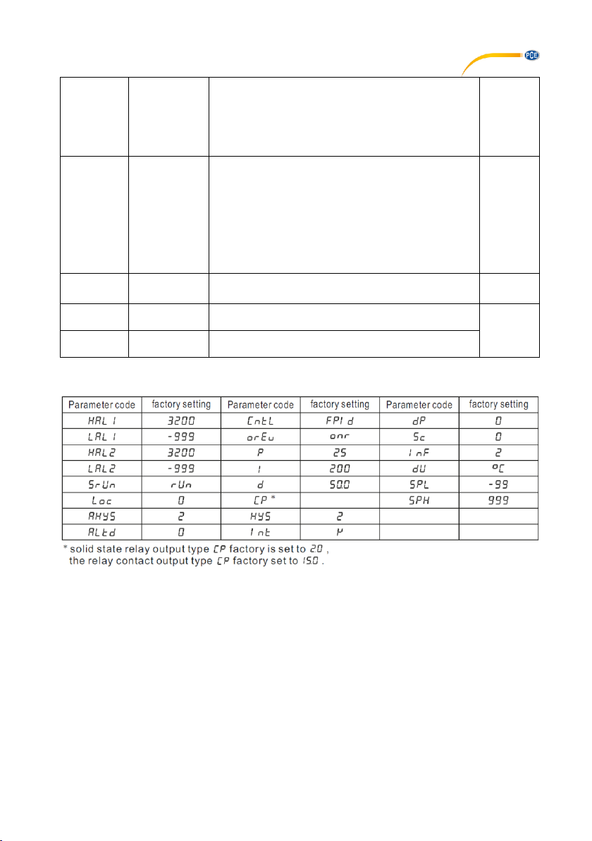
In the field parameters,set Loc=800, then press the key to enter the system parameters.
AHYS
Alarm
hysteresis
Avoid frequent alarm on-off action because of the
fluctuation of PV
0~2000
ALtd
Alarm mode
ALtd=0,AL1is the is the. deviation value alarm,AL2
absolute value alarm
ALtd=1,AL1 and AL2 is the absolute value alarm.
ALtd=2,AL1 and AL2 is the deviation value alarm.
0~2
CntL
Control
mode
onoF: on-off control. For situation not requiring high
precision.
FPId: advanced artificial intelligence ”FUZZY PID“
control.
onoF
FPId
orEv
Selection of
heating
refrigeration
onr: Reverse acting. Increase in measured variable
causes a decrease in the output, such as heating
control.
ond: Direct acting. Increase in measured variable
causes an increase in the output, such as
refrigerating control.
onr
ond
P
Proportional
band
Proportional band in PID and APID control. Instead
of percentage of the measurement range, the unit is
the same as PV. Generally, optimal P, I, D and CP
can obtained by auto tuning. They can also be
manually inputted if you already know the correct
Values.
1~32000
I
Integration
time
Integration time
1~9999
seconds
d
Differential
time
No derivative effect when d=0
0~3200
seconds
CP
Control cycle
CP reflect the instrument operator to adjust the
speed, the size of the CP that affect the control
accuracy. With SSR, SCR output control cycle
preferable to shorter, usually 0.5-3.0 Seconds. The
relay switch output is generally in 15-40 sec. When
the output relay switches, the CP will be limited to
3 seconds, and self-tuning At will automatically set
the CP as the appropriate value, taking into account
the control accuracy and mechanical switch life.
When the control mode CntL = onoF, the action of
the CP as an output disconnect or power-on output
ON Delay time.
0.2~
300.0
HYS
Control
hysteresis
HYS is used for on-off control to avoid frequent onoff action of relay. For a reverse acting (heating)
system, when PV > SV, output turns off; when
PV<SV-HYS, output turns on. For a direct acting
(cooling) system, when PV<SV, output turns off;
when PV>SV+HYS, output turns on.
0~200.0
Int
Input Signal
Input spec: K、E、J、N、Pt(Pt100)
dp
Decimal
point
0 (no decimal), 0.0 (one decimal place).
0
0.0
Page 9
© PCE Instruments
7
SC
Input Shift
Adjustment
Sc is used to shift input to compensate the error
caused by transducer, input signal, or auto cold
junction compensation of thermocouple.
PV after compensation=PV before compensation +
Sc It is generally set to 0. The incorrect setting will
cause measurement inaccurate.
-199.9~
+400.0
InF
PV
input filter
The value of InF will determine the ability of filtering
noise. When a large value is set, the measurement
input is stabilized but the response speed is slow.
Generally, it can be set to 1 to 3. If great interference
exists, then you can increase parameter “InF”
gradually to make momentary fluctuation of
measured value less than 2 to 5. When the
instrument is being metrological verified, “InF” s can
be set to 0 or 1 to shorten the response time.
0~40
dU
Temperature
Unit select.
°C:celsius equals
°F:fahenheit equals
°C
°F
SvL
Low limit
of SV
Minimum value that SV is allowed to be.
-999~
+3200
SvH
Upper limit
of SV
Maximum value that SV is allowed to be.
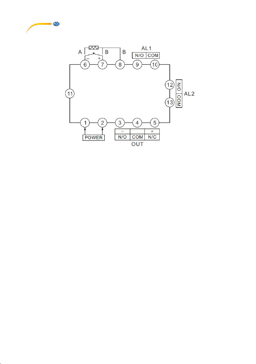
8 Default settings
Page 10
© PCE Instruments
8
9 Wiring diagram
10 Note
(1) Can not normally display measured values in the display window alternating show:
"orAL" character, indicating that the input of the measurement signal abnormalities or Out of
range; check Int parameter settings, and then the input sensor signals are the same category,
if it is determined the same, check the input sensing Signal not pick the wrong line, if it is
determined to not pick the wrong line, check whether the sensor problem, replace another
sensor to try.
(2) The instrument used by the local environmental temperature and humidity can not
exceed the scope of the provisions, the instrument around should allow sufficient space for
heat dissipation, instrument internal temperature rise due to thermal radiation will lead to a
result of the measurement accuracy and service life of the affected. In this Case, to be taken
to a forced cooling fan or other measures to reduce the ambient temperature.
(3) the extension or connection then the thermocouple leads should be used with the
thermocouple type to match the compensation conductor; extend or connect the
thermoelectric Resistance of the lead, you should use the minimal resistance of the wire and
cable away from power lines and load connection, in order to avoid signal interference.
Page 11

© PCE Instruments
9
11 Warranty
You can read our warranty terms in our General Business Terms which you can find here:
https://www.pce-instruments.com/english/terms.
12 Disposal
For the disposal of batteries in the EU, the 2006/66/EC directive of the European Parliament
applies. Due to the contained pollutants, batteries must not be disposed of as household waste.
They must be given to collection points designed for that purpose.
In order to comply with the EU directive 2012/19/EU we take our devices back. We either re-use
them or give them to a recycling company which disposes of the devices in line with law.
For countries outside the EU, batteries and devices should be disposed of in accordance with
your local waste regulations.
If you have any questions, please contact PCE Instruments.
Page 12

© PCE Instruments
10
PCE Instruments contact information
Germany France Spain
PCE Deutschland GmbH PCE Instruments France EURL PCE Ibérica S.L.
Im Langel 4 23, rue de Strasbourg Calle Mayor, 53
D-59872 Meschede 67250 Soultz-Sous-Forets 02500 Tobarra (Albacete)
Deutschland France España
Tel.: +49 (0) 2903 976 99 0 Téléphone: +33 (0) 972 3537 17 Tel. : +34 967 543 548
Fax: +49 (0) 2903 976 99 29 Numéro de fax: +33 (0) 972 3537 18 Fax: +34 967 543 542
[email protected] [email protected] [email protected]
www.pce-instruments.com/deutsch www.pce-instruments.com/french www.pce-instruments.com/espanol
Germany United Kingdom Italy
PCE Produktions- und PCE Instruments UK Ltd PCE Italia s.r.l.
Entwicklungsgesellschaft mbH Unit 11 Southpoint Business Park Via Pesciatina 878 / B-Interno 6
Im Langel 26 Ensign Way, Southampton 55010 Loc. Gragnano
D-59872 Meschede Hampshire Capannori (Lucca)
Deutschland United Kingdom, SO31 4RF Italia
Tel.: +49 (0) 2903 976 99 471 Tel: +44 (0) 2380 98703 0 Telefono: +39 0583 975 114
Fax: +49 (0) 2903 976 99 9971 Fax: +44 (0) 2380 98703 9 Fax: +39 0583 974 824
[email protected] [email protected] [email protected]
www.pce-instruments.com/deutsch www.pce-instruments.com/english www.pce-instruments.com/italiano
The Netherlands China Hong Kong
PCE Brookhuis B.V. PCE (Beijing) Technology Co., Limited PCE Instruments HK Ltd.
Institutenweg 15 1519 Room, 6 Building Unit J, 21/F., COS Centre
7521 PH Enschede Zhong Ang Times Plaza 56 Tsun Yip Street
Nederland No. 9 Mentougou Road, Tou Gou District Kwun Tong
Telefoon: +31 (0)53 737 01 92 102300 Beijing, China Kowloon, Hong Kong
[email protected] Tel: +86 (10) 8893 9660 Tel: +852-301-84912
www.pce-instruments.com/dutch [email protected] [email protected]
www.pce-instruments.cn www.pce-instruments.cn
United States of America Turkey
PCE Americas Inc. PCE Teknik Cihazları Ltd.Şti.
711 Commerce Way suite 8 Halkalı Merkez Mah.
Jupiter / Palm Beach Pehlivan Sok. No.6/C
33458 FL 34303 Küçükçekmece - İstanbul
USA Türkiye
Tel: +1 (561) 320-9162 Tel: 0212 471 11 47
Fax: +1 (561) 320-9176 Faks: 0212 705 53 93
[email protected] [email protected]
www.pce-instruments.com/us www.pce-instruments.com/turkish
 Loading...