

Page 1
Read this document carefully before using this device. The guarantee will be expired by device damages if you don’t attend to the directions
in the user manual. Also we don't accept any compensations for personal injury, material damage or capital disadvantages.
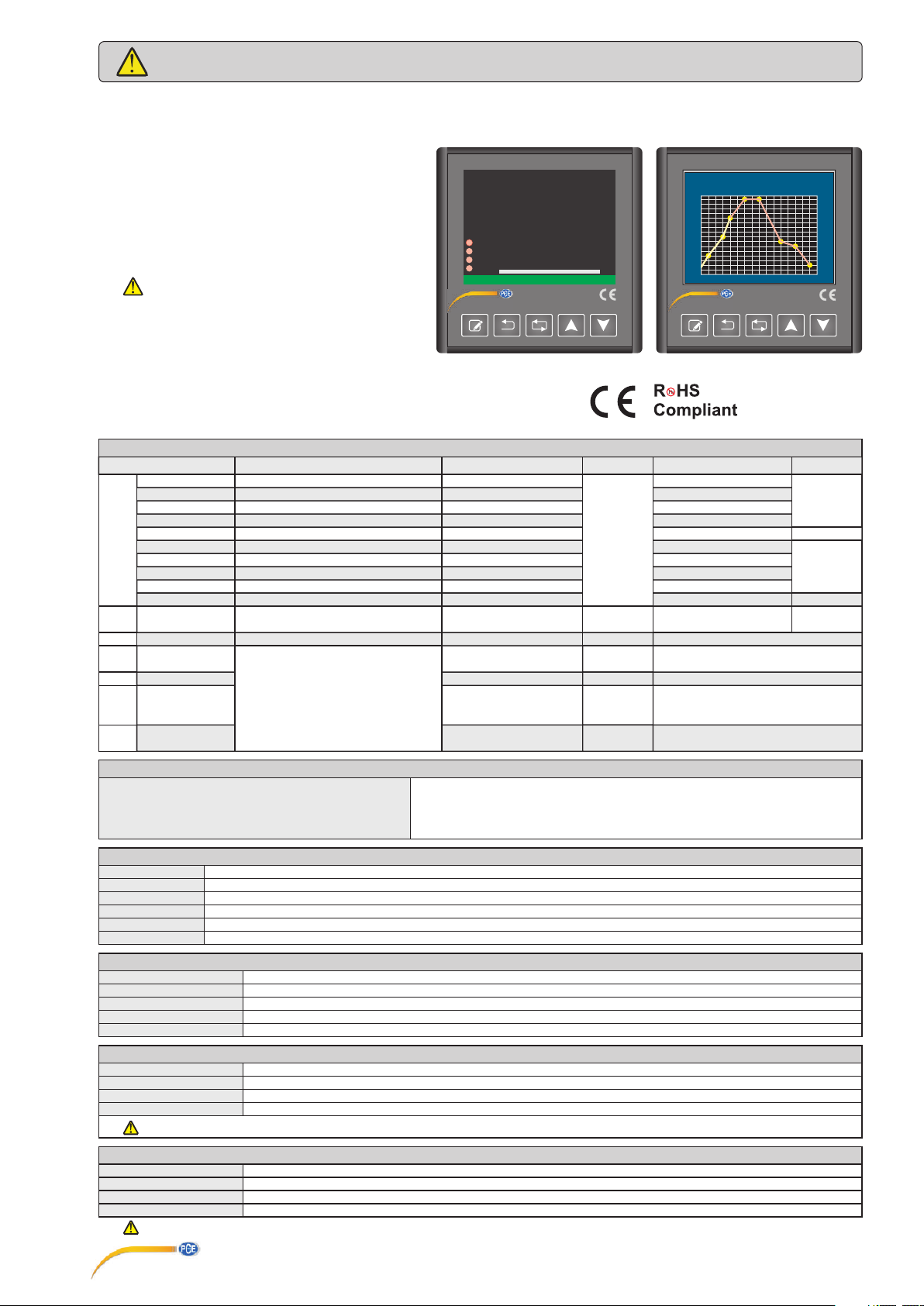
PCE-RE100P Series Programmable Profile Controller
Thank you for choosing PCE-RE100P series programmable profile controller.
* 96x96mm sized.
* 3,5 inches TFT , graphic and 5 digit display.
* Selectable TC, RTD, NTC, R, mA, V or mV inputs.
* Input offset feature
* 32 point linearization for analog inputs.
* Selectable relay, SSR or analog outputs.
* Selectable , input proportional transmitter output(mA or V).
* 50ms sampling time.
* PID control.
* PID selftune.
* PID auto-tune.
Selftune automatic PID calculation or
manually enter PID parameters if known.
* Soft-Start feature.
* 24Vdc for sensor supply.
* 16 program and 8 step for profile control.
* Selectable Single Setpoint Mode or Profile Control Mode.
* Digital inputs for profile control.
* In case of sensor failure manually , periodical or auto-periodical
control can be selected.
* Security levels for menu and configuration pages.
* RS485 ModBus protocol communication feature.(optional)
* CE marked according to Europen Norms.
.
Analog Inputs
B (Pt30Rh-Pt6Rh)
E (NiCr-Con)
J (Fe-Con)
K (NiCr-Ni)
L (Fe-Con)
TC
N (NiCrSi-NiSi)
R (Pt13Rh-Pt)
S (Pt10Rh-Pt)
T (Cu-Con)
U (Cu-Con)
Pt100
RTD
Input Type
200,0 ... 1800,0°C
-100,0 ..... 900,0°C
-100,0 ..... 900,0°C
-100,0 ... 1300,0°C
-100,0 ..... 900,0°C
-200,0 ... 1300,0°C
0,0 ... 1700,0°C
0,0 ... 1700,0°C
-250,0 ..... 300,0°C
-200,0 ..... 400,0°C
-200,0 ..... 850,0°C
-100,00 ... 160,00°C
NTC
mA
mV
NTC
0 - 20mA
4 - 20mA
0 - 150mV
-60,0 ..... 150,0°C
0 - 5V
V
1 - 5V
0 - 10V
0 - 550
Ω
0 - 10kΩΩ
DIGITAL INPUTS (In order to use for profile control process)
Start-Stop Input
Pause-Resume Input
Previous Program Input
Next Program Input
Range
392,0 ... 3272,0°F
-148,0 ... 1652,0°F
-148,0 ... 1652,0°F
-148,0 ... 2372,0°F
-148,0 ... 1652,0°F
-328,0 ... 2372,0°F
32,0 ... 3092,0°F
32,0 ... 3092,0°F
-418,0 ..... 572,0°F
-328,0 ..... 752,0°F
-328,0 ... 1562,0°F
-148,00 .. 320,00°F
-76,0 ..... 302,0°F
-32768 ... 32767
-3276,8 ... 3276,7
-327,68 ... 327,67
-32,768 ... 32,767
5V or 30V pulse , Ri=100kΩ
PV
1230.6
SV
1200.0
A3
A1
Prog.No: Seg.No: 1 1
A2
Prog.Remaining Time(min): 1:0
SSR
PRESS SET TO START PROFILE CONTROLLER
Accuracy
% ±0.1 or ±2°C (3,6°F)
% ±0.1 or ±0,5°C (1°F)
% ±0.1 or ±0,5°C (1°F)
% ±0.1 or ±0,5°C (1°F)
% ±0.1 or ±1.5°C (2.7°F)
% ±0.1 or ±0,5°C (1°F)
% ±0.1 or ±1°C (1.8°F)
% ±0.1 or ±1°C (1.8°F)
% ±0.1 or ±0,5°C (1°F)
% ±0.1 or ±0,5°C (1°F)
% ±0.1 or ±0,5°C (1°F)
% ±0.1 or ±0,5°C (1°F)
% ±0.1 or ±1 digit
% ±0.1 or ±20µV
% ±0.1 or ±1 digit
% ±0.2 or ±0.1Ω
% ±0.5 or ±10Ω
0%
PCE-RE-100P
°C
°C
Input Resist.
Ri > 100kΩ
Ri > 100kΩ
Ri > 100kΩ
Ri = 50Ω
Ri > 100kΩ
Ri > 100kΩ
Ri > 100kΩ
Cable Color
+ undefined
+ purple
+ black
+ green
+ red
+ lilac
+ orange
+ orange
+ brown
+ red
Sensor current 250µA
Sensor current 250µA
PV-SV
Program 1 is running
200
175
150
125
100
75
50
25
0
2 4 6 8 10 12 14 16
PCE-RE-100P
- white
- white
- white
- white
- blue
- white
- white
- white
- white
- brown
min
Standart
EN 60584
DIN43710
EN 60584
DIN43710
EN 60751
OUTPUTS
Control / Alarm 3
Alarm 1
Alarm 2
SSR
mA
V
250V AC, 2A . Selectable as NO+NC.10.000.000 switch without load and 200.000 switch under 250V AC 2A (resistive load)
250V AC, 2A . Selectable as NO+NC.10.000.000 switch without load and 200.000 switch under 250V AC 2A (resistive load)
250V AC, 2A . Selectable as NO.10.000.000 switch without load and 200.000 switch under 250V AC 2A (resistive load)
Max. 40mA , 0 - 12Volt , short-circuit protection.
0 - 20mA or 4 - 20mA , Max. load resistance is 750 .
Ω
Max. 30mA , 0 - 10Volt , short-circuit protection.
ELECTRICAL CHARACTERISTICS
Supply
Power consumption
Wiring
EMC
Safety requirements
90-250V AC, 50/60Hz
Max. 7VA
2.5mm² screw-terminal
EN 61326-1: 2013
EN 61010-1: 2010 (Pollution degree 2 , overvoltage category ||)
ENVIRONMENTAL CONDITIONS
Ambient/storage temp.
Max. Relative humidity
Rated pollution degree
Height
Do not use the device in locations subject to corrosive and flammable gases.
0 ... +50°C/-25 ... 70°C
Relative humidity 80% for temperatures up to 31 .°C , decreasing linearly to 50% relative humidity at 40°C
According to EN 60529 Front panel : IP65 , Rear
Max. 2000m
panel : IP20
HOUSING
Housing type
Dimensions
Weight
Enclosure material
While cleaning the device , solvents(thinner,gasoline,acid etc.) or corrosive materials must not be used.
Suitable for flush-panel mounting.
G96xY96xD81mm
Approx. 400g.
Self extinguishing plastics.
PCE Teknik Cihazlar Paz. Tic. Ltd.Şti.
Halkalı Merkez Mah. Pehlivan Sok. No 6/C
34303 Küçükçekmece/ İstanbul
Türkiye
1/10
TM
PCE-RE100P-EN-03-190211
Page 2
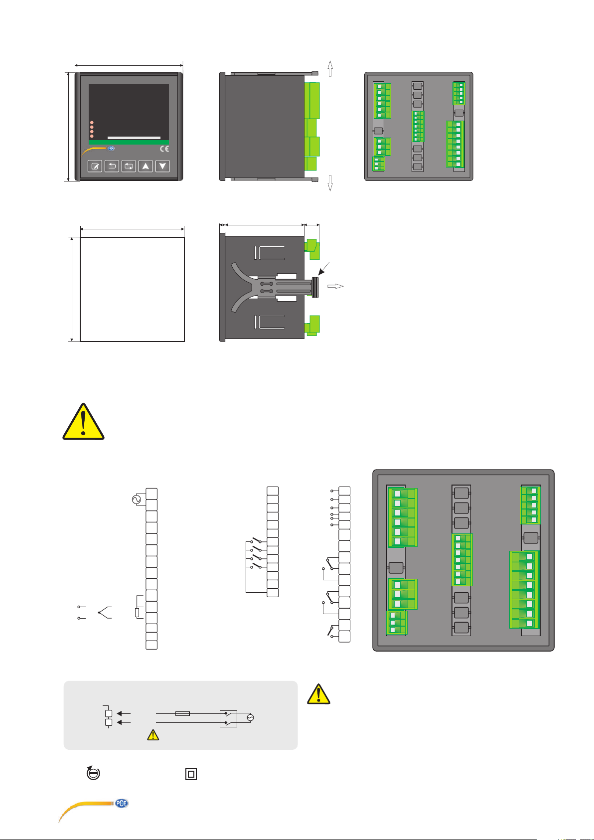
DIMENSIONS
96mm
PV
1230.6
SV
1200.0
A3
A1
Prog.No: Seg.No:
96mm
A2
SSR
PRESS SET TO START PROFILE CONTROLLER
1 1
Prog.Remaining Time(min):
PCE-RE-100P
1
°C
°C
1:0
0%
1
2
3
4
5
6
7
8
9
10
11
12
13
14
15
16
17
18
19
20
21
22
23
24
25
26
27
28
29
30
31
32
33
34
35
36
37
38
39
40
41
42
43
1
PANEL CUT-OUT
92mm
92mm
CONNECTION DIAGRAM
PCE-RE100P is intended for installation in control panels. Make sure that the device is used only for intended purpose. The electrical connections
must carried out by a qualified staff and must be according to the relevant locally applicable regulations. During an installation , all of the cables that
are connected to the device must be free of electrical power. The device must be protected against inadmissible humidity , vibrations , severe soiling
and make sure that the operation temperature is not exceeded. The cables should not be close to the power cables or components.
GND1
RTD
NTC
R
COM
1
2
3
4
5
Previous Program Input
Pause - Resume Input
6
7
Next Program Input
8
9
10
11
12
13
14
A
15
B
Start - Stop Input
90 - 230V AC
50/60Hz, MAX. 7VA
+24V DC (max. 30mA)
+12V DC (max. 30mA)
+
TCmA/mV/V
--
ModBus
RS 485
+
{
6mm
GND
+12V
69mm
16 29
17 30
18 31
19 32
20 33
15mm
SSR OUT
V OUT
mA OUT
21
22
23
24
Control
25
Alarm 3
26
Valve On
27
28
Alarm 1
Alarm 2
Valve Off
Flush mounting clamp
2
-
++
-
-
+
For removing the device from panel :
- While pressing both flush mounting clamps of the device
in direction 1 , pull it in direction 2.
Not :
1) Panel thickness should be maximum 7mm.
2) If there is no 60mm free space at the back
side of the device , it would be difficult to remove it from
panel.
1
2
3
4
34
35
36
37
38
39
40
41
42
43
5
6
7
8
9
10
11
12
13
14
15
16
17
18
19
20
21
22
23
24
25
26
27
28
29
30
31
32
33
34
35
36
37
38
39
40
41
42
43
SUPPLY VOLTAGE
90-250V AC
50/60Hz
MAX. 7VA
1
2
Neutral
Holding screw
0.4-0.5Nm
F 100 mA 250V AC
Switch
Line
Fuse should be
connected.
PCE Teknik Cihazlar Paz. Tic. Ltd.Şti.
Halkalı Merkez Mah. Pehlivan Sok. No 6/C
34303 Küçükçekmece/ İstanbul
Türkiye
Cable size: 1,5mm²
Equipment is protected throughout
by DOUBLE INSULATION.
90-230V AC
50/60Hz
MAX. 7VA
2/10
Logic output of the instrument is not electrically insulated from the
internal circuits. Therefore , when using grounding thermocouple , do
not connect the logic output terminals to the ground.
Not :
1) Main supply cords shall meet the requirements of IEC 60227 or
IEC60245.
2)In accordance with safety regulations,the power supply switch shall
bring the identification of the relevant instrument and it should be easily
accessible by the operator.
PCE-RE100P-EN-03-190211
Page 3
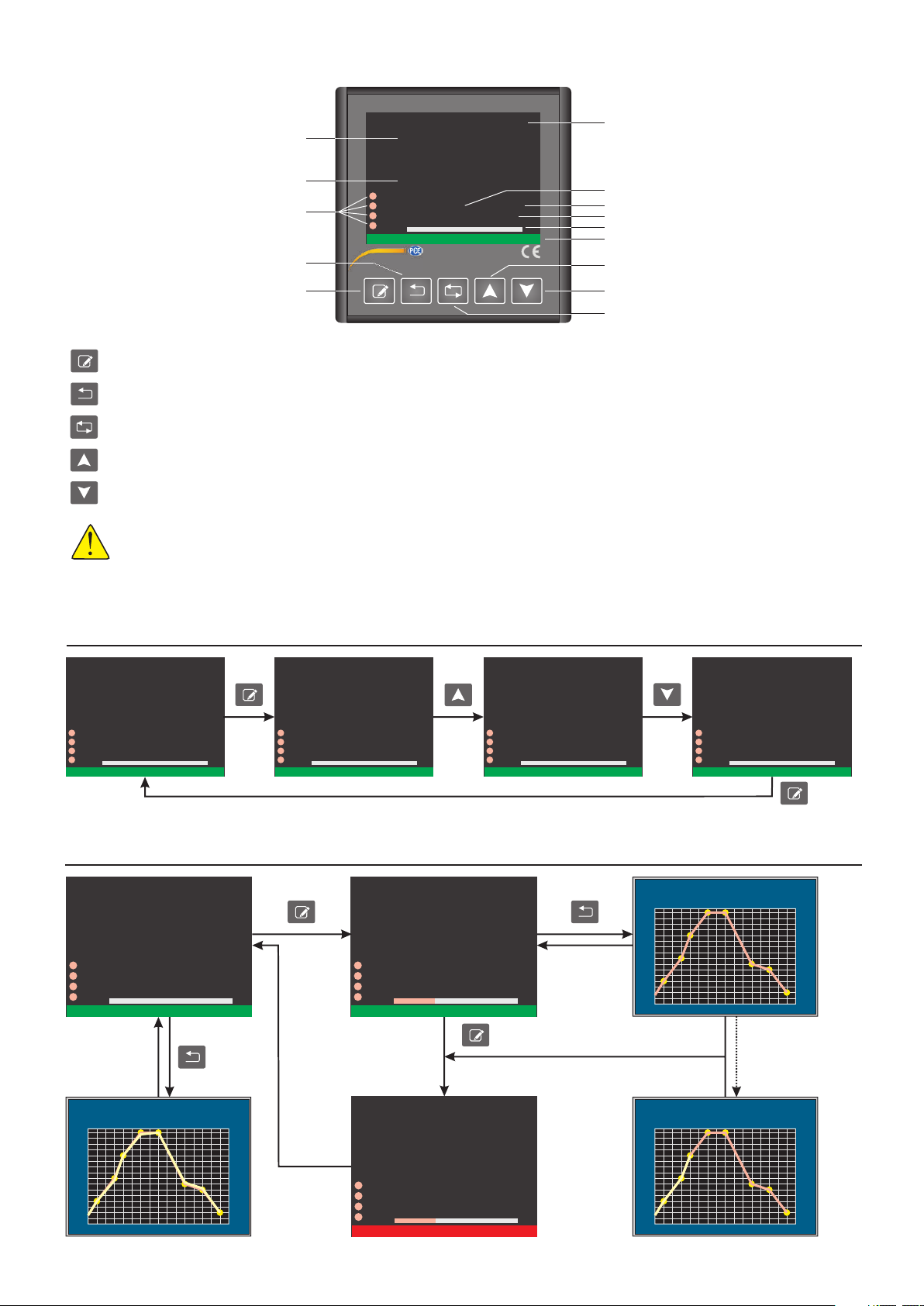
HOME SCREEN
Unit
Program Number
Segment Number
Remaining time in min.
% Output ratio
Message box
Increase Key
Decrease Key
Input Key
°C
°C
1:0
PV
Process Value
123.4
SV
Set Value
Ouput/ Alarm Relay and SSR status.
(If output is active,related led turns to green.)
Back Key
SET Key
SET Key : Start/Stop profile controller in “Profile Controller Mode”, Select/Unselect parameter for increase/decrease parameter value in “Programming Mode”.
Back Key :
Enter Key :
Increase Key :
Decrease Key :
NOTE 1 : Device must be in “Profile Control Mode” in order to start/stop profile control by pressing Set Key.
NOTE 2 : When device in “Single Setpoint Mode”, Prog.No , Seg.No ve Prog.Remaning Time(min) informations are not shown on home screen.
NOTE 3 : If Increase Key is held down while the device is powered up , factory parameters will be restored.
NOTE 4 : “Single Setpoint Mode” can be selected under “Profile Controller Configuration Page” sub menu , device make a control related to SV ,
which can be adjusted on home screen in “Single Setpoint Mode”.
Change SV in “Single Setpoint Mode”.
Return previous page in “Programming Mode”.
Enter main menu and open sub pages and transition between sub pages in “Programming Mode”.
Pause/Resume profile controller in “Profile Controller Mode”.
Transition between parameters (when parameter background is red)
and increase selected parameter value (when parameter background is green) in “Programming Mode”.
Transition between parameters (when parameter background is red)
and decrease selected parameter value (when parameter background is green) in “Programming Mode”.
200.0
A3
A1
Prog.No: Seg.No:
A2
Prog.Remaining Time(min):
SSR
PRESS SET TO START PROFILE CONTROLLER
1 1
0%
PCE-RE-100P
Adjusting Device Set Value in Single Setpoint Mode
PV
123.4
SV
200.0
A3
A1
A2
SSR
SINGLE SET POINT MODE IS RUNNING
If Set Key pressed once , SV’s color will be green. In this case SV is adjusted by pressing Increase/Decrease keys.
If Set Key pressed again or by waiting 3 seconds , SV’s color will be white on home screen.
0%
°C
°C
PV
123.4
SV
200.0
A3 A3 A3
A1 A1 A1
A2 A2 A2
SSR
SINGLE SET POINT MODE IS RUNNING SINGLE SET POINT MODE IS RUNNING SINGLE SET POINT MODE IS RUNNING
0% 0% 0%
°C
°C
PV
123.4
SV
200.1
SSR
Profile Control Mode
PV
23.4
SV
A3 A3
A1 A1
A2 A2
SSR
Last saved program
graph can be shown
by pressing Back Key.
50.0
Prog.No: Seg.No:
Prog.Remaining Time(min):
PRESS SET KEY TO START PROFILE CONTROL PROFILE CONTROL IS RUNNING
0 0 Prog.No: Seg.No: 1 1
0% 33%
°C
°C
Profile control
0:0 Prog.Remaining Time(min):
is started by
pressing
Set Key.
Profile control is stopped by
pressing Set Key and “PROFILE
CONTROLLER IS STOPPED”
message is given for 3 seconds
and device is turned back to
PV
23.4
SV
home screen.
PV
50.0
SSR
23.4
SV
A3
A1
A2
SSR
50.0
Prog.No: Seg.No: 1 1
Prog.Remaining Time(min):
PROFILE CONTROLLER IS STOPPED
33%
°C
°C
14:59
°C
°C
14:59
Profile control
program graph
by pressing
is shown
Back Key.
°C
°C
PV-SV
200
175
150
125
100
75
50
25
0
PV-SVPV-SV
200200
175175
150150
125125
100100
7575
5050
2525
00
PV
123.4
SV
200.0
SSR
Program 1 is running
22244466688810
Program 1 is running Profil control is finished.
PV is sampled and saved
once in every minute and
shown on program graph.
1010
min
12
14
16
minmin
1212
1414
1616
°C
°C
3/10
PCE-RE100P-EN-03-190211
Page 4
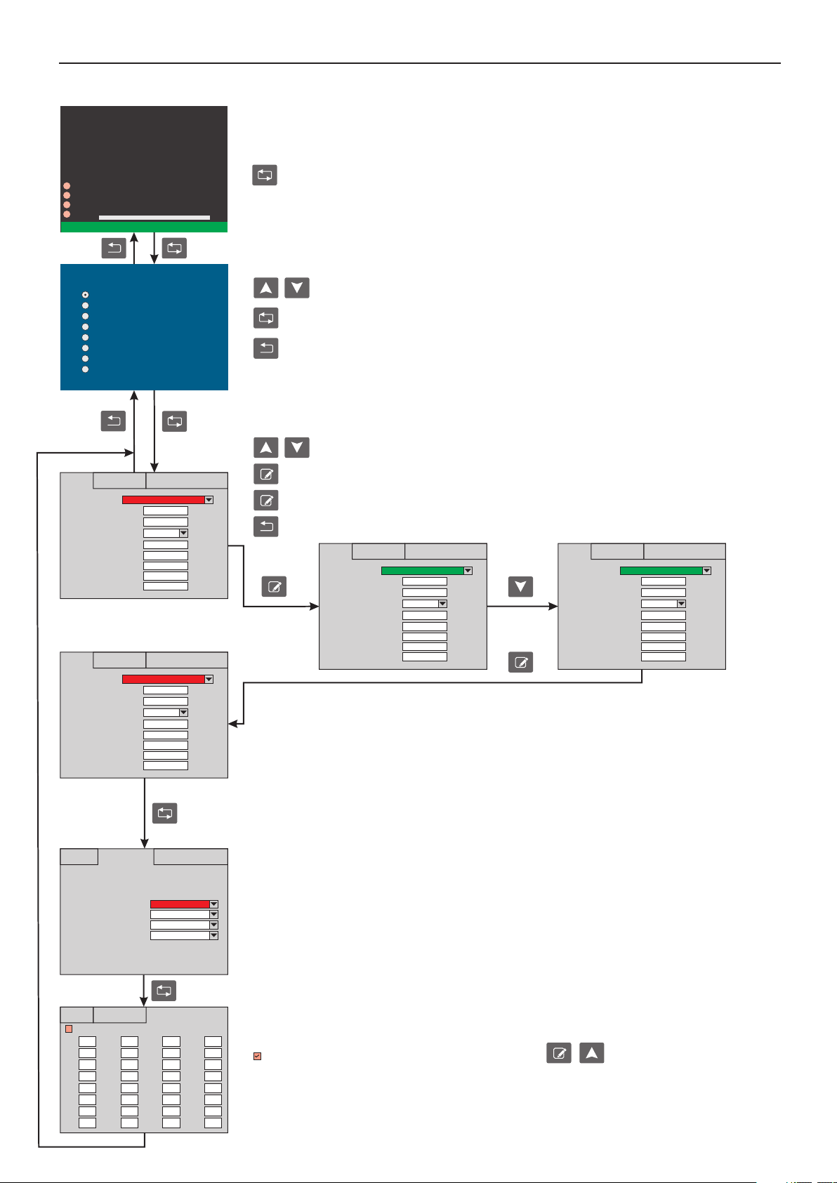
Programming
Home Screen
PV
123.4
SV
200.0
A3
A1
Prog.No: Seg.No:
A2
Prog.Remaining Time(min):
SSR
PRESS SET TO START PROFILE CONTROLLER
0 0
0%
°C
°C
0:0
Main menu is opened and “Programming Mode” is started by pressing Enter Key for 2 seconds.
PCE-RE100P PROFILE CONTROLLER
Input Configuration Page
Output Configuration Page
Alarm Configuration Page
PID Control Configuration Page
Communication Configuration Page
Security Configuration Page
Calibration Page
Profile Controller Configuration Page
Digital Inputs Conf
Input Conf
Input 1 Type
Scale Minimum
Scale Maxmimum
Unit
Input offset
Coefficient of digital filter
Decimal Point
Minimum Set Value
Maximum Set Value
Digital Inputs Conf
Input Conf
Input 1 Type
Scale Minimum
Scale Maxmimum
Unit
Input offset
Coefficient of digital filter
Decimal Point
Minimum Set Value
Maximum Set Value
Digital Inputs Conf
Input Conf
Start - Stop Input:
Pause - Resume Input:
Previous Program Input:
Next Program Input:
Linearization Table Conf
J Type Thermocouple
-100.0
900.0
°C
0
4
XXX.X
-100.0
900.0
Linearization Table Conf
K Type Thermocouple
-100.0
1300.0
°C
0
4
XXX.X
-100.0
1300.0
Linearization Table Conf
Keypad
Digital Input
Keypad - Digital Input
Keypad
Desired sub menu is selected by pressing Increase/Decrease Keys.
Selected sub menu is opened by pressing Enter Key.
Selected sub menu can be opened if permission is given from “Security Configuration Page”.
If Back Key is pressed or by waiting 10 seconds , parameters will be saved and device turns back to home screen.
NOT 5 : If power failure is occurs while device is programming , parameters won’t be saved.
Programming Inputs (Input Configuration Page)
Desired parameter is selected by pressing Increase/Decrease Keys. Background of selected parameter turns red.
If SET Key is pressed , background of selected parameter turns to green and selected parameter can be adjusted to
desired value.
If SET Key is pressed again , background of selected parameter turns to red and exits from parameter adjustment.
If Back Key pressed or by waiting 10 seconds , Input Configuration Page is closed and device turns back to main menu.
Digital Inputs Conf Digital Inputs Conf
Input Conf Input Conf
Input 1 Type Input 1 Type
Scale Minimum Scale Minimum
Scale Maxmimum Scale Maxmimum
Unit Unit
Input offset Input offset
Coefficient of digital filter Coefficient of digital filter
Decimal Point Decimal Point
Minimum Set Value Minimum Set Value
Maximum Set Value Maximum Set Value
Input 1 Type :
B, E, J, K, L, N, R, S, T, U, Pt100,
NTC, 0-20mA, 4-20mA, 0-5V, 1-5V,
0-10V, 0-150mV, 0-550 ,
0-10kΩ Ω
Scale(Scale Min./Max.) :
Adjustable between
-32768 ... 32767
(Just for mA, V, mV, W, kW)
Minimum Set Value :
Adjustable between
Scale Minimum and
Maximum Set Value.
Digital Inputs : Start/Stop , Pause/Resume , Next/Previous Program processes can be made by
digital inputs or device keypad.
If process will be performed only by Keypad ,“Keypad” must be selected.
If process will be performed only by Digital Input ,“Digital Input” must be selected.
If process will be performed both by Keypad and Digital Input ,“Keypad and Digital Input” must be selected.
Start/Stop : Start-Stop Input and/or SET key.
Pause/Resume : Pause-Resume Input and/or Back key.
Previous program : Previous Program Input and/or Increase key.
Next program : Next Program Input and/or Decrease key.
Linearization Table Conf Linearization Table Conf
J Type Thermocouple K Type Thermocouple
-100.0 -100.0
900.0 1300.0
°C °C
0 0
4 4
XXX.X XXX.X
-100.0 -100.0
900.0 1300.0
Maximum Set Value :
Adjustable between
Scale Maximum and
Minimum Set Value.
Unit :
°C, °F, bar, %RH, Hz, mA, A,
mV, V, Ohm, kOhm, %, g, kg,
Input offset :
Adjustable between -99 ... 99.
Coefficient of digital filter :
1=200ms and it is device sampling time.
Adjustable between 1 ... 32.
Value of parameter should be increased in
interference.
cm, m, m/s, m/min, km/h,
cm3/s, m3/h, l/s, l/min, l/h
(Just for mA, V, mV, W, kW)
Decimal Point :
According to range table ,
1, 2 and 3 digit can be selected.
Digital Inputs Conf
Input Conf
Use Linearizasyon Table for 0-10 V
0.00
0.00 2.58 5.16 7.74
0.00
0.32 2.90 5.48 8.06
0.00
0.65 3.23 5.81 8.39
0.97 3.55 6.13 8.71
0.00
1.29 3.87 6.45 9.03
0.00
1.61 4.19 6.77 9.35
0.00
1.94 4.52 7.10 9.68
0.00
2.26 4.84 7.42 10.00
0.00
0.00
0.00
0.00
0.00
0.00
0.00
0.00
0.00
Linearization Table Conf
0.00
0.00
0.00
0.00
0.00
0.00
0.00
0.00
0.00
0.00
0.00
0.00
0.00
0.00
0.00
0.00
Linearization Table Conf :
If input type is selected as mA, V, mV, W or kW, linearizaton can be done at 32 points.
Use Linearization Table for 0-10 V can be activated by pressing keys respectively.
Corresponding values of input signals must be entered to table in order to linearize at 32 points.
4/10
PCE-RE100P-EN-03-190211
Page 5
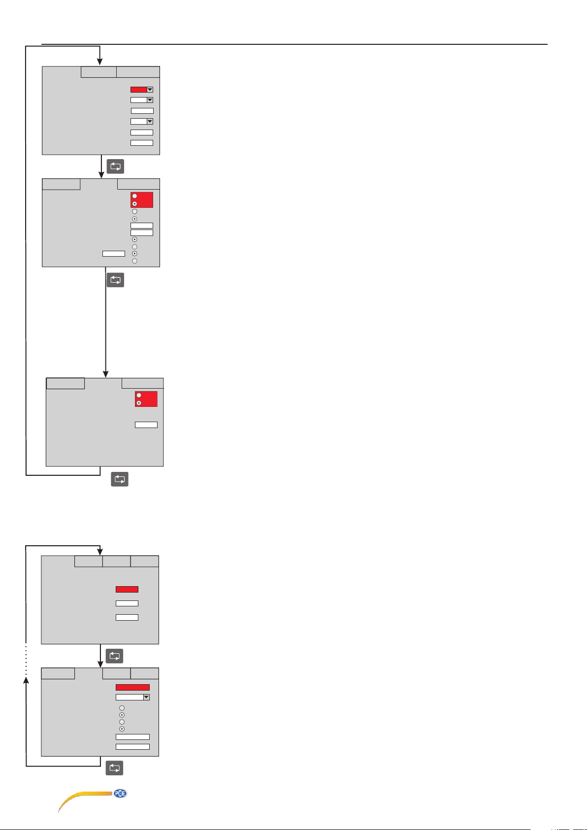
Programming
Output Conf
Output Type
Re-Transmission
Maxmimum Analog Output Value(%)
Minimum Analog Output Value(%)
Output Hysteresis
Output Power Offset Around Set Point(%)
Output Conf
Control Configuration
Power Failure Behaviour
Output Power During Prob Failure(%)
Soft Start Time(sec)
Consistently Control
SV Deviation
Control Conf
Control Conf
0
Valve Conf
Relay
None
100
0
0
0
Valve Conf
COOL
HEAT
Stop
Resume
0
10
1010
OFF
ON
OFF
ON
Programming Outputs(Output Configuration Page)
Output Type : Relay, SSR, Valve, or . If relay is not selected for output type , relay
can be configured as Alarm3.
Re-Transmission : If output type is selected as relay or SSR , re-transmission can be selected as a 0/4 or V.
If output type is selected as a 0/4-20mA , re-transmission can be selected as a 0-10V.
If output type is selected as 0-10V , re-transmission can be selected as a 0/4-20mA.
Maximum Analog Output Value : % maximum analog output value.
Minimum Analog Output Value : % minimum analog output value.
Output Hysteresis : Adjustable between 0... 50. (If Proportional Band selected 0.0 , ON-OFF control and
output hysteresis will be active.)
Output Power Offset Around Set Point : Output power offset around SV according to error. In order to reach to SV fast.
TotalOuput(%) = system output(%)+ (100 / Proportional Band) *error *OutputPowerOffset/100.
Control Configuration : Selectable as Cool/Heat control. The cooling control is only ON-OFF control
(For Cooling control. Proportional Band must be 0.0).
Power Failure Behaviour : If power failure occurs when profile control is running and device is powered on after power failure:
- If Stop is selected , profile control stops and turns to initial state.
- If Resume is selected , profile control resumes from where it is stopped.
Output Power During Prob Failure(%) : Adjustable between %0 ... %100. Output will continue in case of prob failure.
Soft Start Time(sec) : Adjustable between 0 ... 200 seconds.
If device is in profile control mode , programmed segments of profile control starts according to soft start time.
If device is in “Single Setpoint Mode” , device starts to control according to soft start time after device is powered on.
Consistently Control : When profile control is finished ; If OFF is selected , profile control stops and turns to initial state.
If ON is selected , profile control continues to control at last set value.
SV Deviation : End of the every profile control step , If difference between process value and set value is bigger than
SV Deviation value ( SV - PV > SV Deviation ) then time countdown is paused and control remains at last set value until
difference between process value and set value is smaller than SV Deviation value ( SV - PV < SV Deviation ).
SV Deviation process can be enabled/disabled with ON/OFF option.
0-20mA, 4-20mA 0-10V
-20mA 0-10
Output Conf
Valve Position When Power On
Control Conf
Valve On/Off Time(sn)
Alarm Set Conf
Alarm Set Conf
Alarm 1 Conf Alarm 2 Conf
Alarm 1 Set Value
Alarm 2 Set Value
Alarm 3 Set Value
Alarm 1 Conf Alarm 2 Conf
Alarm 1 Hysteresis
Alarm 1 Type
Alarm 1 Status
Alarm 1 Status During Prob Failure
Alarm 1 Up Limit
Alarm 1 Low Limit
Valve Conf
Alarm 3 Conf
150.0
500.0
850.0
Alarm 3 Conf
0
Independent
LOW
HIGH
OFF
ON
160.00
-100.00
Valve Position When Power On : When device is pwer on, it provides to change to valve position.
Close
Open
200
Valve On/Off Time(sn): It can set between 0-500 seconds.
Programming Alarms(Alarm Configuration Page)
Alarm 1 Set Value : Adjustable between Alarm 1 Up Limit and Alarm 1 Low Limit.
Alarm 2 Set Value : Adjustable between Alarm 2 Up Limit and Alarm 2 Low Limit.
Alarm 3 Set Value : Adjustable between Alarm 3 Up Limit and Alarm 3 Low Limit.
(In order to use Alarm 3 , Output Type parameter must be different from Relay otherwise
Alarm 3 will be unavailable and Alarm 3 Conf page will be hidden.
Alarm 1 Hysteresis : Adjustable between 0 ... 50.
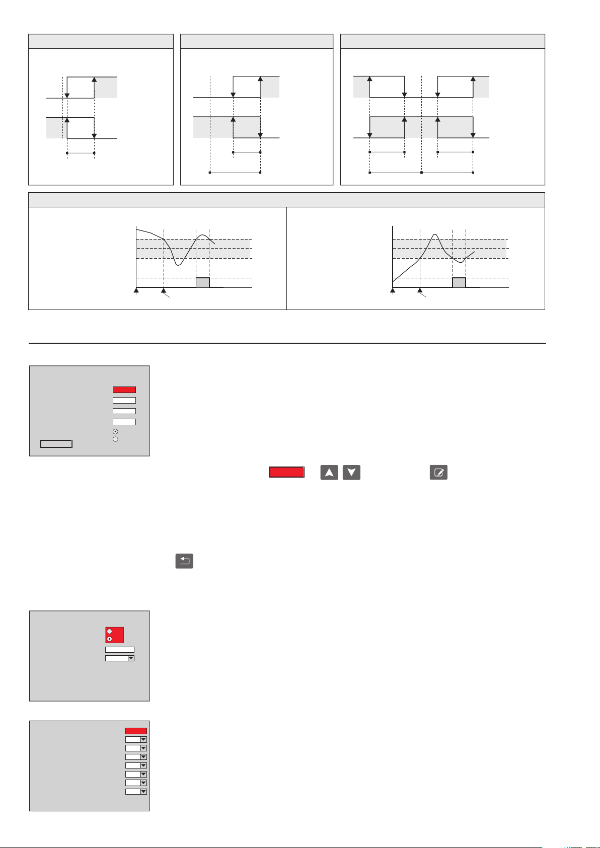
Alarm 1 Type : Independent alarm, Deviation alarm, Band alarm, Band Alarm with Inhibition or
Profil control alarm can be selected. (In order to select Profile control segment alarms , Alarm 1 segments
in Alarm Conf sub page of Profile Controller Configuration Page should be selected.
Alarm 1 Status : For the Independent alarm, Band alarm or Band Alarm with Inhibition to be active below the set value
LOW must be selected , to be active above the set value HIGH must be selected. If LOW is seleced for Band alarm ,
alarm will be activated in band. If HIGH is selected , alarm will be activated out of band.
Alarm 1 Status During Probe Failure : For the alarm to be active in case of prob failure ON must be selected.
For the alarm to be inactive in case of prob failure OFF must be selected.
Alarm 1 Up Limit : Adjustable between Scale Maximum and Alarm 1 Low Limit.
Alarm 1 Low Limit : Adjustable between Scale Minimum and Alarm 1 Up Limit.
Alarm 2 “Alarm 2 Conf” and Alarm 3 “Alarm 3 Conf” are programmed in the same way.
PCE Teknik Cihazlar Paz. Tic. Ltd.Şti.
Halkalı Merkez Mah. Pehlivan Sok. No 6/C
34303 Küçükçekmece/ İstanbul
Türkiye
5/10
PCE-RE100P-EN-03-190211
Page 6
Independent Alarm
Deviation Alarm
Band Alarm
Set
Value
OFF
ON
Alarm
Hysteresis
Alarm Set
Value
Set Value+ Alarm Set Value
Set Value- Alarm Set Value
Programming
ON
OFF
Set Value
OFF
Beginning
of procedure
Alarm Status
HIGH
Alarm Status
LOW
ON
OFF
ON
Alarm Status : HIGH
Band alarm is possible
Set
Value
Set
Value
Alarm
Hysteresis
Alarm Set
+
Value
ON
OFF
Alarm Status
HIGH
Alarm Status
LOW
Band Alarm with Inhibition
Alarm
Hysteresis
Set
Value
Set Value+ Alarm Set Value
Set Value- Alarm Set Value
Set Value
ON
OFF
Beginning
of procedure
Value
OFF
Alarm Set
_
Value
Alarm Status : LOW
Set
ON
Alarm
Hysteresis
Alarm Set
Set
+
Value
Value
Band alarm is possible
ONON
OFFOFF
Alarm Status
HIGH
Alarm Status
LOW
PID Control Conf
Proportional Band (%)
Integral Time (min)
Derivative Time (min)
Control Period (sec)
Auto Tune
Start Selftune
Modbus Conf
Modbus Communication
Device Address
Baudrate
1
9600
OFF
ON
Programming PID Control (PID Control Configuration Page)
Proportional Band (%) : Adjustable between %0.0 ... %100.0.
4.0
4.0
1.0
4
OFF
ON
If proportional band is selected 0.0 , ON-OFF control will be activated.
Integral Time (min) : Adjustable between 0.0 ... 100.0 minute.
Derivate Time (min) : Adjustable between 0.0 ... 25.0 minute.
Control Period (sec) : Adjustable between 0 ... 250 second.
Auto Tune : Improve PID parameters while Self Tune is running.
if PV is oscillating while profile controller is running , auto tune improves PID parameters in order to best control.
It will be activated if ON selected.
PID Self Tune :
Self Tune is started by selecting with keys and pressing by key. SELF TUNE IS
Start Selftune
STARTED and SELF TUNE IS RUNNING messages is shown respectively.
When Self Tune process is successful:
- SELF TUNE IS FINISHED, PRESS BACK TO EXIT message is shown and waits for user intervention in profile control mode.
- SELF TUNE IS FINISHED, SINGLE SETPOINT IS RUNNING message is shown and continues to control.
In order to start Selftune process PV must be smaller than %60 of SV , otherwise SELF TUNE IS STARTED and
SELF TUNE IS STOPPED messages are shown respectively and home screen returned.
User must wait until PV drops under %60 of SV and start selftune again.
If key is pressed, SELF TUNE IS STOPPED message is shown and selftune is stopped and device turns back to
home screen.
Programming ModBus (Communication Configuration Page)
Modbus Communication : If parameter is selected ON modbus will be active , otherwise will be inactive.
Device Address : Adjustable between 1 ... 247
Baudrate : 4800, 9600, 19200, 38400 or 57600.
Security Code
Input Configuration Page Visibility
Output Configuration Page Visibility
Alarm Configuration Page Visibility
PID Control Configuration Page Visibility
Communication Configuration Page Visibility
Calibration Page Visibility
Profile Controller Configuration Page Visibility
Enter security code in order to change page visibilities.
0
Yes
Yes
Yes
Yes
Yes
Yes
Yes
Programming Keypad Security Level(Security Configuration Page)
Security Code : In order to change security configuration , Security Code must be entered 123.
Input Configuration Page Visibility : Yes, No or None.
Output Configuration Page Visibility : Yes, No or None.
Alarm Configuration Page Visibility : Yes, No or None.
PID Control Configuration Page Visibility : Yes, No or None.
Communication Configuration Page Visibility : Yes, No or None.
Calibration Page Visibility : Yes or None.
Profile Controller Configuration Page Visibility : Yes, No or None.
No : Page can be opened , parameters can not be changed.
Yes : Page can be opened , parameters can be changed. None : Page can not be opened.
6/10
PCE-RE100P-EN-03-190211
Page 7
Program Conf
Program No:
Program Start Delay (min.): Time(min.) Temp.
Max. Step Count :
Program Repeat Count :
Next Program :
Alarms Conf
Soft Start Conf
1 1
Start Program: Single Setpoint
0 0.0
8
1
0
Segment1:
Segment2:
Segment3
Segment4
Segment5
Segment6
Segment7
Segment8
0
0
0
0
0
0
0
0
Graph Page
0.0
0.0
0.0
0.0
0.0
0.0
0.0
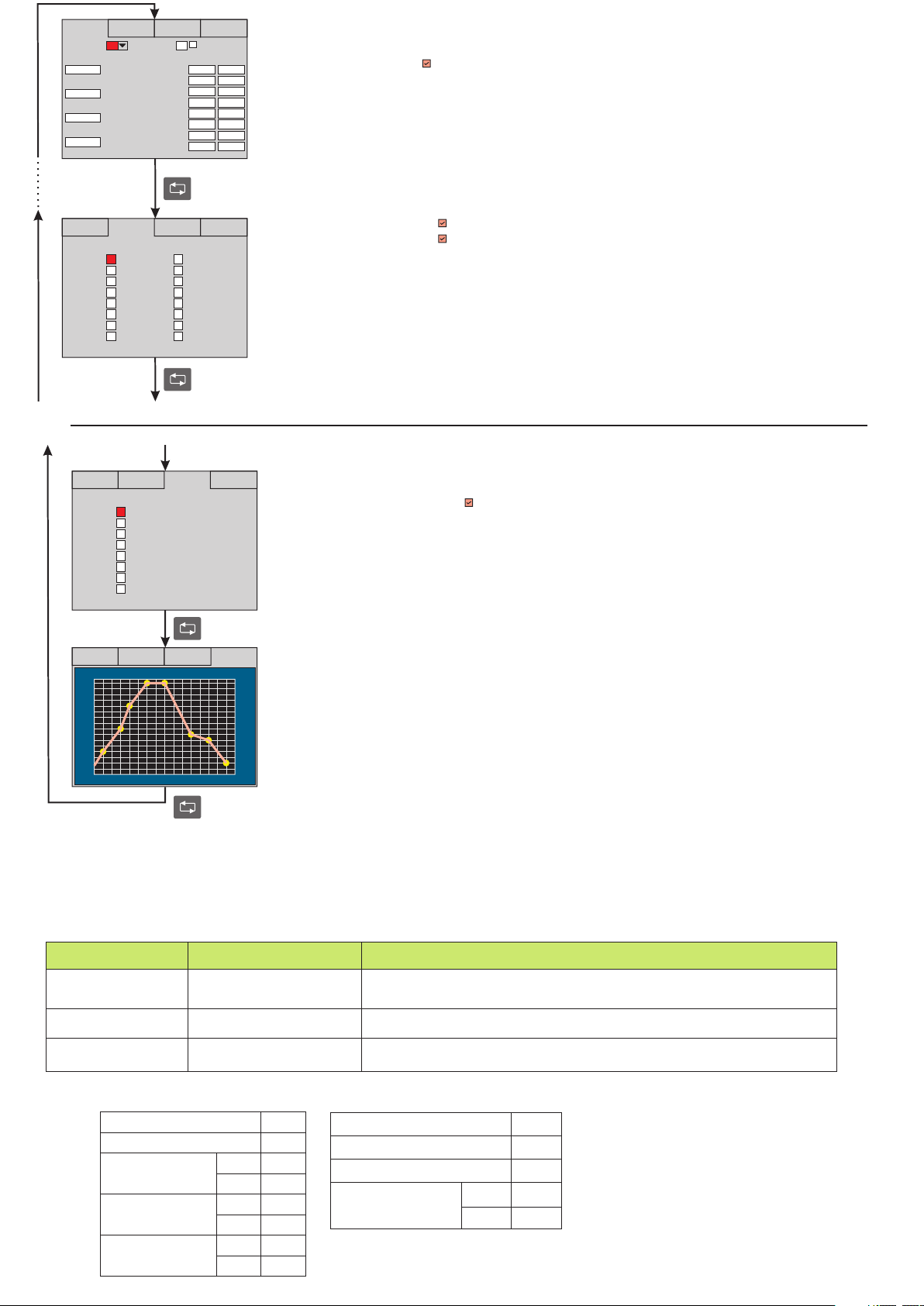
Programming Profile Controller (Profile Controller Configuration Page)
Program No : Adjustable between 1 ... 16.
Start Program : Adjustable 1 ... 16.
Single Setpoint : If checkbox is selected , single set point will be activated.(In this case profile controller is inactive)
Program Start Delay(min.) : Adjustable between 0 ... 180.
Max. Step Count : Adjustable between 1 ... 8.
Program Repeat Count : Adjustable between 1 ... 8.
Next Program : Adjustable between 0 ... 16. If 0 is selected , control will be stopped at end of the program.
Segment1/Time(min.) : Adjustable between 0 ... 32000 min.
Segment1/Temp : Adjustable between Minimum Set Value and Maximum Set Value parameters.
2 ... 8. Segments are programmed in the same way., 3
Program Conf
Alarms Conf
Alarm1 Alarm2
Segment1
Segment2
Segment3
Segment4
Segment5
Segment6
Segment7
Segment8
Program1 Segment Alarms
Soft Start Conf
Programming
Program Conf
Program Conf
Alarms Conf Soft Start Conf
Soft Start
Segment1
Segment2
Segment3
Segment4
Segment5
Segment6
Segment7
Segment8
Program1 Segment Soft Starts
Alarms Conf Soft Start Conf
Program 1 Graph
SV
200
175
150
125
100
75
50
25
0
2 4 6 8 10 12 14 16
Graph Page
Graph Page
Graph Page
Segment1/Alarm1 : If checkbox is selected , Alarm1 will be activated.
Segment1/Alarm2 : If checkbox is selected , Alarm2 will be activated.
2 ... 8. Segments, 3 are programmed in the same way.
If Alarm Type parameter is selected profile control alarm , Alarm1 and Alarm2 can be configured for the profile controller.
Soft Start Conf :
1. Segment Soft Start : If checkbox is selected , Soft Start will be activated.
Value of Soft Start Time parameter will be used as a selected segment’s soft start time.
2 ... 8. Segments are programmed in the same way., 3
Graph Page :
Configuration can be seen from Graph Page.
- Program number,
- Set values of segments
- Segment counts
- Segment lenght
min
MODBUS ERROR MESSAGES
Modbus protocol has two types error, communication error and operating error. Reason of the communication error is data corruption in transmission. Parity and CRC
control should be done to prevent communication error. Receiver side checks parity and CRC of the data. If they are wrong, the message will be ignored. If format of the
data is true but function doesn’t perform for any reason, operating error occurs. Slave realizes error and sends error message. Most significant bit of function is changed '1'
to indicate error in error message by slave. Error code is sent in data section. Master realizes error type via this message.
ModBus Error Codes
Error Code
01
02
03
Message example;
Structure of command message (Byte Format)
Beginning address
of coils.
Number of coils (N)
CRC DATA
ILLEGAL FUNCTION
ILLEGAL DATA ADDRESS
ILLEGAL DATA VALUE
Device Address
Function Code
Name
MSB
LSB
MSB
LSB
LSB
MSB
(0A)h
(01)h
(04)h
(A1)h
(00)h
(01)h
(AC)h
(63)h
The function code received in the query is not an allowable action for the slave. If a
Poll Program Complete command was issued, this code indicates that no program
function preceded it.
The data address received in the query is not an allowable address for the slave.
A value contained in the query data field is not an allowable value for the slave.
Structure of response message (Byte Format)
Device Address
Function Code
Error Code
CRC DATA
LSB
MSB
7/10
Meaning
(0A)h
(81)h
(02)h
(B0)h
(53)h
PCE-RE100P-EN-03-190211
Page 8
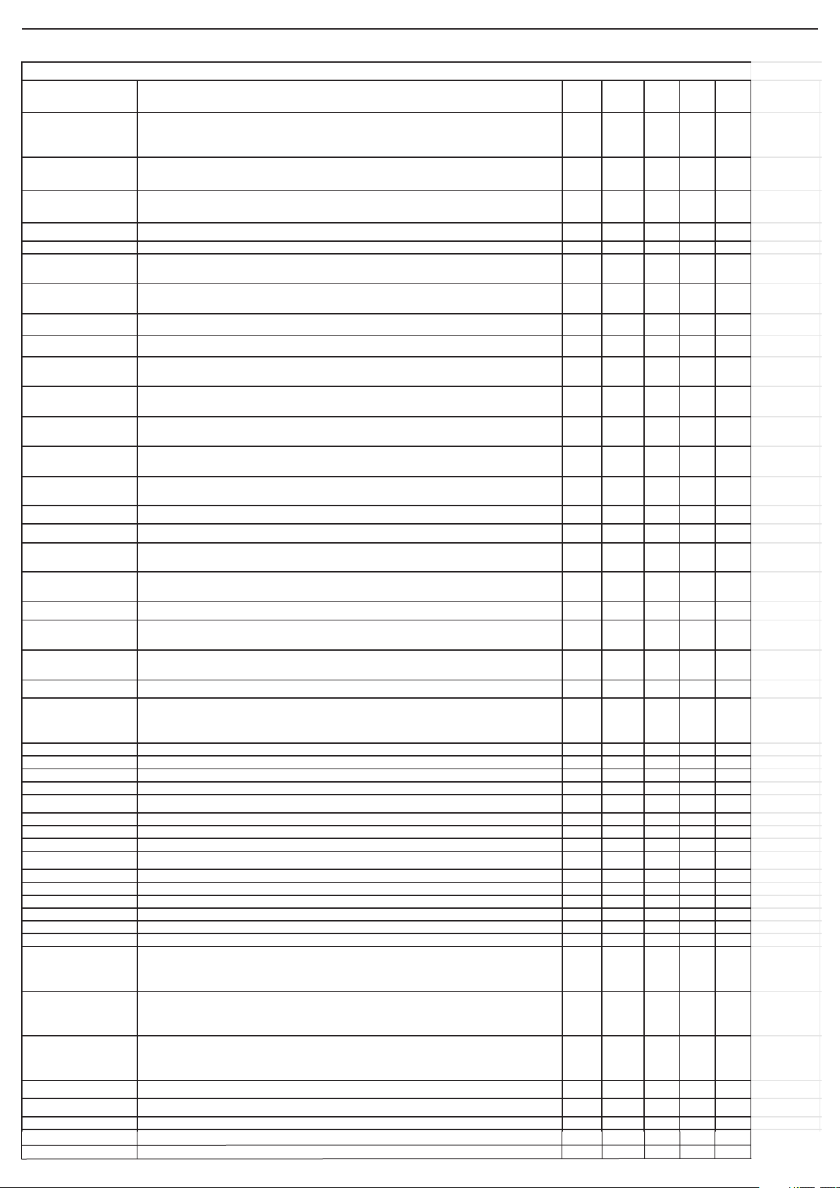
Modbus Address Map
PARAMETER INFORMATI ON DATA
TYPE
REG .
ADR.
MİN. MAX. DEF.
Input Type 0 = B type Termokupl 1 = E 2 = J 3 = K 4 = L 5 = N 6 = R 7 = S
8 = T 9 = U 10 = Pt100 11= N TC 12 = 0-20 mA 13 = 4-2 0 mA 14 = 0-5 V 15 = 1-5 V
16 = 0-1 0 V 17 = 0-1 50 mV 18 = 0-550 Oh m 19 = 0-10 kOhm
Wo rd 0 0 19 2
Scale Minimum Can not be chang ed for Thermocou ple an d PT100 . Can be changed for U niv ersal In put s.
Scale Minimum is -10 0 for P T100 XXX.XX. Low limit for Set Val ue parameter.
Wo rd 1 -32768 32 767 -1 000
Scale Maximum Can not be ch anged for Th ermo coupl e and P T1 00 . Can be changed fo r Uni versal Inputs.
Scale Maximum is 160 for PT100 XXX.XX. Up li mit fo r Set Value parameter.
Wo rd 2 -32768 32 767 9 000
Unit 0 = °C 1 = °F 2 = Bar 3 = %RH 4 = Hz 5 = A 6 = V . Wo rd 3 0 6 0
Input Of fset Offs et added to Meas urement. Wo rd 4 -99 99 0
Digital Filter Coef fici ent 1 = Fast est response time 32 = Slo west respo nse ti me
Value of parameter sh oul d be increased in in terference.
Wo rd 5 1 32 4
Decima l Point 0 = XXX 1 = XXX.X 2 = XXX.XX 3= XXX.XXX . Accırd ing to Deci mal P oint parameter , modbus
read/ writ e data chan ged by 1,10,100,10 00 l inearl y.
Wo rd 6 0 3 1
Minimum Set Value A dju stab le between Scale Minimum and Maximum Set Valu e parameters . Wo rd 7 0 3 1
Maximum Set Value A dju stab le between Scale Mak simum and Mini mu m Set Val ue parameters. Wo rd 8 0 3 1
Start - Stop Input 0=D isab le 1= En able
P rofil Control st art/s top digital inpu t di sabl e/enab le.
Wo rd 9 0 1 0
Pause - Res ume Input 0= Di sabl e 1= Enable
P rofil Control pau se/res ume di git al input di sabl e/enab le.
Wo rd 10 0 1 0
Previous Program Input 0= Disable 1= Enab le
P rofil Control prev iou s pro gram digital inp ut disab le/en able.
Wo rd 11 0 1 0
Next Program Input 0 = Disable 1= Enabl e
P rofil Control next p rogram dig ital inpu t di sabl e/enab le.
Wo rd 12 0 1 0
Linearization Table
[0-31].Points
Li nearizat ion table , valu e of points fro m 0 to 31 . Word [13 -44] -327 68 3 276 7 0
Output Type 0 = Relay 1 = SSR 2 = 0-2 0 mA 3 = 4-2 0 mA 4 = 0-10 V Word 45 0 4 0
Re-Tra nsmi ssi on 0 = Non e 1 = 0-20 mA 2 = 4-20 mA 3 = 0-10 V Wo rd 46 0 3 0
Maximum Analog
Output Value
Wo rd 47 0 1 00 100
Minimum Analog Output
Value
Wo rd 48 0 1 00 0
Output Hysteresi s A djus tabl e betw een 1 and 50. Wo rd 49 0 5 0 0
Output Power Off set
Around Set Po int(%)
Ad ded offset(%) accordi ng t o error arou nd Set Value. Wo rd 50 0 1 00 0
Output Power During
Prob Failure(%)
Aj ust able between %0 and %100 , outp ut wi ll con tin ue in case of pro b failure. Wo rd 51 0 1 00 0
Sof t Start Time(s ec) A djus tabl e betw een 0 and 200 seconds. Wo rd 52 0 2 00 10
SV Deviation If (SV - PV > SV Deviat ion) at the end of the s tep and If SV Deviation is enabl ed , time cou ntd own
wi ll be p aused and con trol remains at last set value un til (SV - PV < SV Deviation ) Please check
parameter defini tio n on page 5.
Wo rd 53 0 3 276 7 0
Alarm 1 Set Value Wo rd 54 -32 768 32767 10 00
Alarm 2 Set Value Wo rd 55 -32 768 32767 10 00
Alarm 3 Set Value Wo rd 56 -32 768 32767 10 00
Alarm 1 Hysteresi s Wo rd 57 0 5 0 0
Alarm 1 Type 0 =Indepen dent 1=D eviat ion 2=Band alarm 3 =Band alarm with in hib itat ion 4=Pro fil cont rol alarm Word 58 0 4 0
Alarm 1 Up Limit Word 59 -32768 3 276 7 90 00
Alarm 1 Low Limit Word 60 -32768 3 276 7 -10 00
Alarm 2 Hysteresi s Wo rd 61 0 5 0 0
Alarm 2 Type 0 =Indepen dent 1=D eviat ion 2=Band alarm 3 =Band alarm with in hib itat ion 4=Pro fil cont rol alarm Word 62 0 4 0
Alarm 2 Up Limit Word 63 -32768 3 276 7 90 00
Alarm 2 Low Limit Word 64 -32768 3 276 7 -10 00
Alarm 3 Hysteresi s Wo rd 65 0 5 0 0
Alarm 3 Type 0 =Indepen dent 1=D eviat ion 2=Band alarm 3 =Band alarm with in hib itat ion Wo rd 66 0 3 0
Alarm 3 Up Limit Word 67 -32768 3 276 7 90 00
Alarm 3 Low Limit Word 68 -32768 3 276 7 -10 00
Proporti onal Band (%) If it is set to %0.0 , ON-O FF cont rol is activ ated. If it is set to di fferent from %0.0 , PID cont rol is
acti vated . In order to read /wri te from modbu s mu tipl e/di vid e wit h 10. For example ; in order t o set
%5.5 , 5.5x10 =55 must be writ ten to parameter.
Wo rd 69 0 1 00 4
Integral Time (min) Ad jus tabl e between 0.0 and 100 .0.
If it i s set to 0.0 , PD contro l is acti vated. In ord er to read/ writ e from modbus mu tip le/d ivi de wi th 10.
For exampl e ; in order to s et %5.5 , 5.5x10=55 must b e written to parameter.
Wo rd 70 0 1 00 4
Derivative Time (min) Ad jus tabl e betw een 0.0 and 25.0
If it i s set to 0.0 , PI con trol i s activ ated. In ord er to read/write fro m modb us muti ple/ div ide with 10 .
For exampl e ; in order to s et %5.5 , 5.5x10=55 must b e written to parameter.
Wo rd 71 0 2 5 1
Control Period (sec) Ad jus tabl e between 1 and 250 second . Wo rd 72 1 2 50 4
Start Program P rofil e control's start ing program nu mb er. Wo rd 73 1 1 6 1
Set Value Wo rd 74 -32 768 32767 20 00
Holding Registers
PARAMETER LIST
Valve Position When Power On
Valve On/Off Time (sn)
When device is pwer on, it provides to change to valve position.
It can set between 0-500 seconds.
5 = Valve
8/10
Bit
Word
75
76
0
0
200
0
PCE-RE100P-EN-03-190211
1
500
Page 9
Related to Decimal Point parameter; Scale Minimum , Scale Maximum , Linearization Table Points , Alarm 1 Set Value , Alarm 2 Set Value , Alarm 3 Set Value , Alarm 1 Up Limit ,
PARAMETER INFORMATION DATA
TYPE
REG .
ADR.
MİN. MAX. DEF.
Start Delay(mi n.) Delay before pro gram start ing. Word 1 000 + ( Pro gramNo-1 ) x 20 0 1 80 0
Max. Step Count Number of segments . Word 100 0 + ( Prog ramNo -1 ) x 20 + 1 1 8 8
Repeat Count Repeat count of program. Word 1 000 + ( Pro gramNo-1 ) x 20 + 2 1 8 1
Next Program Number of next pro gram. W ord 10 00 + ( Pro gramNo -1 ) x 20 + 3 0 1 6 0
Program Segment1
Time(min.)
Program segment1' s time Word 1 000 + ( Pro gramNo-1 ) x 20 + 4 0 32000 0
Program Segment1 Set
Value
Program segment1' s valu e W ord 10 00 + ( Pro gramNo-1 ) x 20 + 5 -3 200 0 3 2000 0
Program Segment2
Time(min.)
Program segment2' s time Word 1 000 + ( Pro gramNo-1 ) x 20 + 6 0 32000 0
Program Segment2 Set
Value
Program segment2' s valu e W ord 10 00 + ( Pro gramNo-1 ) x 20 + 7 -3 200 0 3 2000 0
Program Segment3
Time(min.)
Program segment3' s time Word 1 000 + ( Pro gramNo-1 ) x 20 + 8 0 32000 0
Program Segment3 Set
Value
Program segment3' s valu e W ord 10 00 + ( Pro gramNo-1 ) x 20 + 9 -3 200 0 3 2000 0
Program Segment4
Time(min.)
Program segment4' s time Word 1 000 + ( Pro gramNo-1 ) x 20 + 100 320 00 0
Program Segment4 Set
Value
Program segment4' s valu e W ord 10 00 + ( Pro gramNo-1 ) x 20 + 11-32000 3 2000 0
Program Segment5
Time(min.)
Program segment5' s time Word 1 000 + ( Pro gramNo-1 ) x 20 + 120 320 00 0
Program Segment5 Set
Value
Program segment5' s valu e W ord 10 00 + ( Pro gramNo-1 ) x 20 + 13-32000 3 2000 0
Program Segment6
Time(min.)
Program segment6' s time Word 1 000 + ( Pro gramNo-1 ) x 20 + 140 320 00 0
Program Segment6 Set
Value
Program segment6' s valu e W ord 10 00 + ( Pro gramNo-1 ) x 20 + 15-32000 3 2000 0
Program Segment7
Time(min.)
Program segment7' s time Word 1 000 + ( Pro gramNo-1 ) x 20 + 160 320 00 0
Program Segment7 Set
Value
Program segment7' s valu e W ord 10 00 + ( Pro gramNo-1 ) x 20 + 17-32000 3 2000 0
Program Segment8
Time(min.)
Program segment8' s time Word 1 000 + ( Pro gramNo-1 ) x 20 + 180 320 00 0
Program Segment8 Set
Value
Program segment8' s valu e W ord 10 00 + ( Pro gramNo-1 ) x 20 + 19-32000 3 2000 0
PARAMETER INFORMATION DATA
TYPE
REG .
ADR.
MİN. MAX. DEF.
Measured Value Measu red PV , result must be div ided by 10. For example; If temperature is 32.5 °C , 325 will be read
over mod bus .
Wo rd 0 NONE NONE N ONE
Internal NTC
Temperature
Measu red Intern al NTC temperature , result mus t be di vided by 10. For example; If temp erature i s 32.5
°C , 325 wi ll be read over mod bus.
Wo rd 1 NONE NONE N ONE
Analog Output
Percentage
Ou tput % for 0-1 0V , 0-20mA or 4-20mA W ord 2 N ONE NO NE NON E
Current Progra m
number
Run ning prog ram number wh ile pro fi le controller is run ning . Wo rd 3 NO NE NON E N ONE
Current seg ment number Run ning segment number wh ile pro fil e controller i s runn ing . Wo rd 4 NO NE NON E N ONE
Control Rem aining
Time(min)
Remain ing time of runni ng program Wo rd 5 NONE NONE N ONE
Alarm 1 Low Limit , Alarm 2 Up Limit , Alarm 2 Low Limit , Alarm 3 Up Limit , Alarm 3 Low Limit , Program Segment1 Set Value , Program Segment2 Set Value , Program Segment3
Set Value , Program Segment4 Set Value , Program Segment5 Set Value , Program Segment6 Set Value , Program Segment7 Set Value , Program Segment8 Set Value parameters
are read/written linearly with 1,10,100,1000.
For example ; Decimal Point parameter is 1and If Set Value is 155.5 , Set Value will be read 1555 from modbus.
Profil Control Holding Registers
Profil control modbus addresses start from 1000.
In order to write/read profile program parameters to/from Modbus base address is 1000 + ( ProgramNo-1 ) x 20.
Related to Decimal Point parameter Profil Control Set parameters are read/written linearly with 1,10,100,1000.
For example;
Program5 Start Delay (min.) Holding Register Address is 1000 + (5-1) x 20 = 1080
Program5 Setment6 Time (min.) Holding Register Address is 1000 + (5-1) x 20 + 14 = 1094
Input Registers
9/10
PCE-RE100P-EN-03-190211
Page 10
Coil Registers
PARAMETER INFORMATION DATA
TYPE
REG .
ADR.
MİN. MAX. DEF.
Use Linearization Table Di sabl e/Enable Li nearizat ion table
Can no t be us ed for Thermoco uple , PT10 0 and N TC . Can be used for Universal Inputs.
Bit 0 0 1 0
Control Configuration 0=ON-OFF COOLING 1=ON -OFF HEA TING
If Pro port ion al Band parameter is %0 , ON-OFF cont rol acti vated .
Bit 1 0 1 1
Power Fa ilure B ehaviour 0= Sto p 1= Resume
If pow er failure occu rs when profile con trol is run ning and dev ice powered on after po wer fai lure;
If sto p is sel ected , profile control wil l sto p and t urn to init ial state.
If resume is sel ected , profile cont rol wi ll resu me from where it stop ped.
Bit 2 0 1 0
Consistently Control 0 = OFF , profile co ntrol sto ps and turns to in iti al stat e.
1 = ON , profile con trol con tinu e to con trol at las t set value.
Bit 3 0 1 0
Sv Devia tion Enable 0 = OFF , 1 = ON Bit 4 0 1 0
Alarm 1 Status 0= LOW 1= HIG H Bit 5 0 1 1
Alarm 1 Status During
Prob Failure
0=OFF , alarm is i nactive in case of prob failu re.
1=ON , alarm is act ive in case of prob fai lure.
Bit 6 0 1 1
Alarm 2 Status 0= LOW 1= HIG H Bit 7 0 1 1
Alarm 2 Status During
Prob Failure
0=OFF , alarm is i nactive in case of prob failu re.
1=ON , alarm is act ive in case of prob fai lure.
Bit 8 0 1 1
Alarm 3 Status 0= LOW 1= HIG H Bit 9 0 1 1
Alarm 3 Status During
Prob Failure
0=OFF , alarm is i nactive in case of prob failu re.
1=ON , alarm is act ive in case of prob fai lure.
Bit 1 0 0 1 1
Auto Tune 0 = OFF 1 = ON , Improve P ID parameters wh ile sel ft une is running . If PV is oscill atin g whi le
profile cont rol is running , aut otune wil l improve P ID parameters in order to best control.
Bit 1 1 0 1 0
Single Set Point 0 = OFF 1 = ON Bit 12 0 1 0
Function Co il Start/Stop Pro fi le cont rol can be st arted/ sto pped over modbus. If us er write 1 to this coi l , profile controll er will
start/stop.
Bit 1 00 0 1 0
Function Co il
Pause/Resume
Profile con trol can be pau sed/resumed over modbu s. If user write 1 t o thi s coil , pro fi le cont roll er will
pause/resume.
Bit 1 01 0 1 0
Function Co il Next Profile co ntrol can start next pro gram over modb us. If user write 1 to thi s coil , profile co ntro ller wi ll
start to next program.
Bit 1 02 0 1 0
Function Co il Previous P rofile con trol can st art previous p rogram over modbus. If user write 1 to t his coi l , profile controller
will st art to p revious pro gram.
Bit 1 03 0 1 0
PARA METER INFORMATION DATA
TYPE
REG .
ADR.
MİN. MAX. DEF.
C/A3 Output Sta tus Con trol Relay / A larm3 out put state( 0 = OFF , 1 = ON ) Bit 0 NO NE NONE NON E
A1 Output Status Alarm1 o utp ut st ate( 0 = OFF , 1 = ON ) Bit 1 NO NE NONE NON E
A2 Output Statıs Al arm2 ou tpu t stat e( 0 = OFF , 1 = ON ) Bit 2 NO NE NONE NON E
SSR Output Sta tus SSR ou tput st ate( 0 = OFF , 1 = ON ) Bit 3 NO NE NONE NON E
Prof ile Control ler
Runni ng Status
P rofil cont roll er run st ate( 0 = OFF , 1 = ON ) Bit 4 NO NE NONE NON E
Prof ile Control ler Pause
Status
P rofil cont roll er paus e state( 0 = OFF , 1 = ON ) Bi t 5 NO NE NON E N ONE
Prob Fail ure Status P rob failu re( 0 = OFF , 1 = ON ) Bit 6 NO NE NONE NON E
Discrete Input Registers
PCE Teknik Cihazlar Paz. Tic. Ltd.Şti.
Halkalı Merkez Mah. Pehlivan Sok. No 6/C
34303 Küçükçekmece/ İstanbul
Türkiye
10/10
PCE-RE100P-EN-03-190211
 Loading...