

Page 1
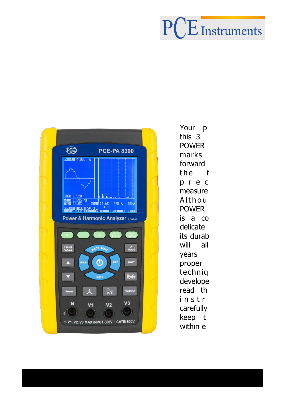
SD card real time data recorder
Y
f
R
f
A
R
f
with harmonic measurement
3 PHASE
Data Logger
PCE-PA 8300
PCE Americas Inc.
711 Commerce Way
Suite 8
Jupiter
FL-33458
USA
From outside US: +1
Tel: (561) 320-9162
Fax: (561) 320-9176
[email protected]
www.pce-instruments.com/english
www.pce-instruments.com
our purchase o
this 3 PHASE
POWER ANALYZE
marks a step
forward for you into
t h e f i e ld o
p recision
measurement.
l t hough t his
POWER ANALYZE
is a complex and
delicate instrument,
its durable structure
will allow many
years of use i
proper operating
techniques are
developed. Please
read the following
instru cti o n s
carefully and always
keep this manual
within easy reach.
PCE Instruments UK Ltd.
Southpoint Business Park
Hampshire / Southampton
United Kingdom, SO31 4RF
Units 12/13
Ensign way
From outside UK: +44
Tel: (0) 2380 98703 0
Fax: (0) 2380 98703 9
OPERATION MANUAL
Page 2
Caution Symbol
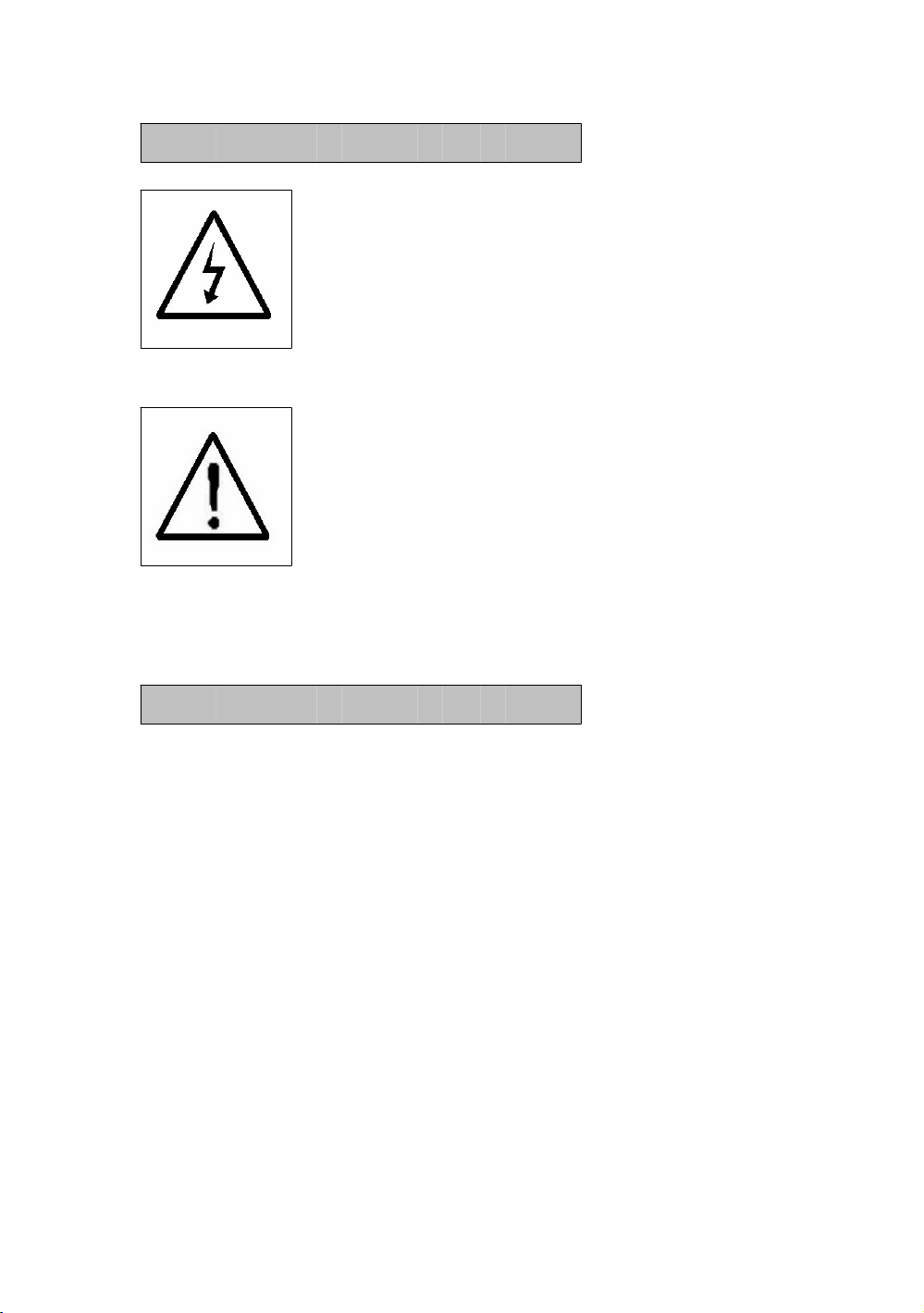
Caution :
* Risk of electric shock !
* During the measurement,
do not open the cabinet.
Caution :
* Do not apply the overload
voltage, current to the input
terminal !
* Remove test leads before open
the battery cover !
* Cleaning - Only use the dry
cloth to clean the plastic case !
Environment Conditions
* Installation Categories III 600V.
* Pollution Degree 2.
* Altitude up to 2000 meters.
* Indoor use.
* Relative humidity 80% max.
Page 3

TABLE OF CONTENTS
.
.
.
.
.
1. FEATURES................................................................1
2. SPECIFICATIONS.....................................................
2-1 General Specifications........................................
2-2 Electrical Specifications.......................................5
3. FRONT PANEL DESCRIPTION.....................................10
4. MEASURING PREPARATION ......................................13
4-1 The original screen.............................................
4-2 Entry the measurement Screen............................ 13
4-3 The summary description of keyboard.................. 15
4-4 SETUP KEY description........................................ 16
4-5 Setting function description before measuring....... 17
5. MEASURING PROCEDURES ....................................... 46
5-1 1Φ 2W ( one phase by two wires )
measurement..................................................... 46
5-2 1Φ 3W ( one phase by three wires )
measurement..................................................... 47
5-3 3Φ 3W ( three phase by three wires )
measurement..................................................... 49
5-4 3Φ 4W ( three phase by four wires )
measurement..................................................... 50
5-5 The CT and PT measurement...............................52
5-6 ZERO adjustment for Watt Hour...........................53
5-7 Harmonic Function Measurement ........................
5-8 Graphic Phasor Diagram...................................... 56
5-9 Voltage/Current Waveform..................................
5-10 Transient Capture ( Dips, Swells, Outage ).......... 60
5-11 Data Logger function.........................................63
5-12 Data Hold function............................................ 65
2
2
13
54
58
Page 4

5-13 Backlight key.....................................................66
.
.
.
.
5-14 A ( Current ) Range key.....................................66
5-15 LOWBAT screen................................................ 67
5-16 Appendix 1.......................................................
68
6. MAINTENANCE......................................................... 69
6-1 Cleaning.............................................................69
6-2 Replacement of batteries .................................... 69
7. RS232 PC SERIAL INTERFACE...................................
8. Download the saving data from the SD card to
the computer ( EXCEL software ) .............................. 72
9. PATENT...................................................................
10. THE ADDRESS OF AFTER SERVICE CENTER ............
70
76
77
Page 5

1. FEATURES
* Analysis for 3 phase multi-power system, 1P/2W, 1P/3W,
3P/3W, 3P/4W.
* 3 current probes ( CP-1201 ) are included, if change the
current probes, the calibration procedures are not
necessary.
* Current probe input signal/ranges with selection :
Input signal (ACV) :
200 mV/300 mV/500 mV/1 V/2 V/3 V.
Ranges (ACA) :
20 A/200 A/2000 A/30 A/300 A/ 3000 A.
* Meter can cooperate the universal current probes.
* Complete set with 4 PCs Test Leads, 4 PCs Alligator clips,
3 PCs Clamp Probe ( CP 1201 ), AC to DC 9V adapter, 2
G SD memory card and Carrying bag.
*Measurement :
V (phase-to-phase), V (phase-to-ground)
A (phase-to-ground)
KW / KVA / KVAR / PF (phase)
KW / KVA / KVAR / PF (system)
KWH / KVAH / KVARH / PFH (system)
Phase angle
* Harmonics display (1-50th order).
* Simultaneous display of Harmonics and Wave form.
* Display of Waveform with Peak Values.
* Analysis of Total Harmonic Distortion ( THD ).
* Graphic Phase diagram with 3-Phase system parameters.
* 3 phase Voltage or Current Unbalanced Ratio ( VUR, AUR )
and Unbalanced Factor.
* Calculated Unbalanced Current through Neutral Line ( An )
* Capture Transient events (including Dip, Swell and
Outage ) with programmable threshold ( % ).
* Programmable CT ratio ( 1 to 600 ) and PT ratio ( 1 to
1000 ).
1
Page 6
* ACV input impedance is 10 Mega ohms.
* Safety Standard : IEC 1010, CAT III 600V.
* Built-in clock and Calendar, real time data record with SD
memory card , sampling time set from 2 to 7200
seconds. Just slot in the SD card into the computer, it
can down load the all the measured value with the time
information ( year, month, data, hour, minute, second )
to the Excel directly, then user can make the further data
analysis by themselves.
* Powered by AA ( UM-3 ) DC 1.5 V X 8 batteries ( Alkaline
type ) or DC 9V adapter.
* Computer data output, can cooperate with optional USB
Cable/USB-01, RS232 cable/UPCB-02 and Data
Acquisition software, SW-811.
* Optional current probes : CP-1201, CP-2000, CP-200,
CP-3000, detail specification.
* User can order the meter only ( without the current
probes ) with the special request as intend to cooperate
their own current probes.
*Patented.
2. SPECIFICATIONS
2-1 General Specifications:
Circuit Custom one-chip of microprocessor LSI
circuit
Display * LCD Size :
81.4 X 61 mm ( 3.2 X 2.4 inch )
* Dot Matrix LCD (320 X 240 pixels )
with back light.
2
Page 7
Measurement * V (phase-to-phase)
* V (phase-to-ground)
* A (phase-to-ground)
* KW / KVA / KVAR / PF (phase)
KW / KVA / KVAR / PF (system)
KWH / KVAH / KVARH / PFH (system)
* Power factor
* Phase angle
* Frequency
* Harmonics display.
Wire 1P/2W, 1P/3W, 3P/3W, 3P/4W.
connections
Voltage ranges 10 ACV to 600 ACV, auto range.
Current probe * Current probe input signal volage ( ACV ) :
input signal
200mV/300mV/500mV/1V/2V/3V.
and range * Current probe input current range ( ACA ) :
20 A/200A/2000A (1200 A)/30A/300A/3000A
* Meter can cooperate the universal current probe.
Safety IEC1010 CAT III 600 V.
standard
ACV input 10 Mega ohms.
impedance
Range select ACV Auto range.
ACA Manual range.
Clamp 40 Hz to 1 KHz.
frequency
response
Spec. tested 45 to 65 Hz.
frequency
Over load ACV 720 ACV rms
protection ACA 1300 ACA with clamp probe
* For the Clamp ,CP-1201
Over Indicator * LCD display show " OL ".
* The data save into the SD card will show
" 9999 " or " 999 "
( overleap the decimal point ).
3
Page 8
Under Indicator * LCD display show " UR ".
* The data save into the SD card will show
" 9999 " or " 999 "
( overleap the decimal point ).
Data Hold Freeze the display reading.
Data Record SD Card Record.
Sampling Time Approx. 1 second.
Power ON/OFF Manual OFF by push button.
Real time * Real time data logger, saved the data
data logger into SD memory card and down load
the all the measured value with the
time information ( year/month/data/
hour/minute/second ) down load
to the Excel
* Integration time for data logger :
2 seconds to 7200 seconds, the during
of setting step are 2 seconds.
Data Output RS232 computer serial interface :
USB/RS232 * Connect the optional USB cable
* Computer
interface
USB-01 will get the USB plug.
* Connect the optional RS232 cable
UPCB-02 will get the RS232
plug.
Operating 0 to 50 ( 32 to 122 ).℃℉
Temperature
Operating Less than 80% R.H..
Humidity
Power Supply * DC 1.5V, AA ( UM-3 ) Battery X 8 PCs
(Alkaline or heavy-duty battery).
* AC to DC 9V power adapter.
Power * Meter : 270 DCmA.
Consumption * Clamp : 22 DCmA.
Clamp max. 50 mm ( 2.0 inch ) Dia.
conductor Size
* For the Clamp ,CP-1201
4
Page 9
Weight * Meter : 1010g ( includes batteries )
T
.
A
.
g
* Clamp ( includded cable ) : 500g
Dimension
Meter :
225 X 125 X 64 mm
( 8.86 X 4.92 X 2.52 inch )
Clamp :
210 X 64 X 33mm
( 8.3 X 2.5 X 1.3 inch )
Clamp Jaw : 86 mm (3.4 inch)- outside
Accessories * Instruction manual.............. 1 PC
Included *
Optional * 2000 Amp current probe, CP-2000
Accessories
est Leads (TL88-4AT)........ 1 Set (4 PCs)
* Alligator clips (TL88-4AC) 1 Set (4 PCs)
* Clamp Probe ( CP-1201 ).....
*
C to DC 9V adapter............1 PC
* SD card ( 2 G )...................
* Carryin
* 200 Amp current probe, CP-200
* Flexible 3000 Amp current probe,
bag....................... 1 PC
3 PCs
1 PC
CP-3000
* USB Cable , USB-01
* RS232 cable, UPCB-02
* Data Acquisition software, SW-U811
* EXCEL Data Acquisition software,
SW-E802
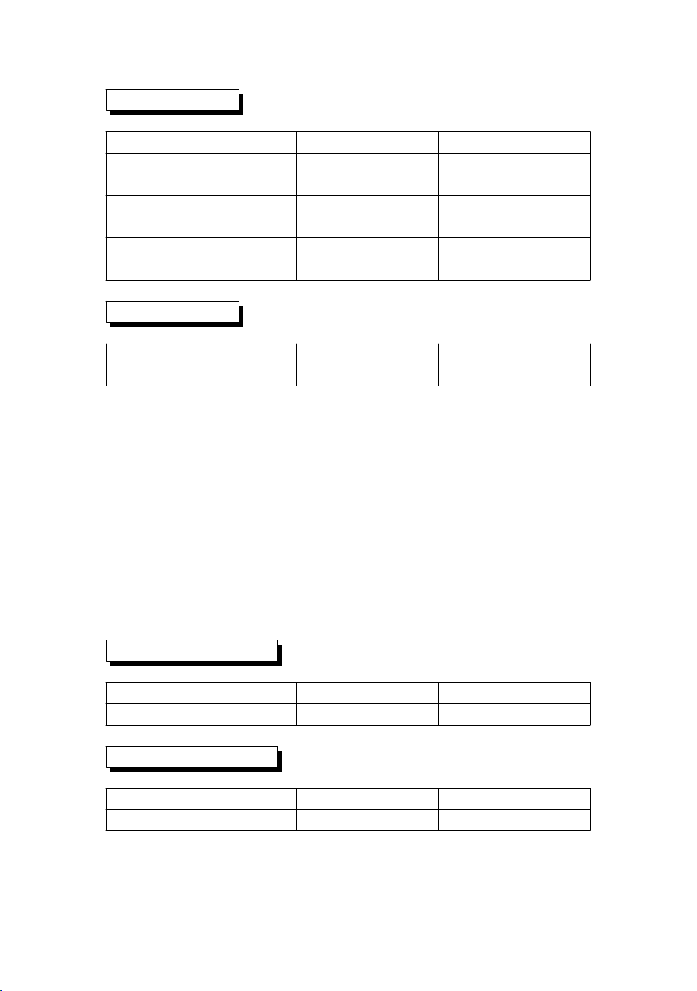
2-2 Electrical Specifications:
ACV
Range Resolution Accuracy
10.0V to 600.0V 0.1V ± (0.5%+0.5V)
* Phase to neutral line
10.0V to 600.0V
* Phase to phase
5
Page 10
ACA
Range Resolution Accuracy
20A 0.001A,
0.01A,
200A 0.01A,
0.1A,
1200A 0.1A,
1A,
Power factor
< 10 A
10 A≧
< 100 A
100 A≧
< 1000 A
1000 A≧
± (0.5%+0.1A)
± (0.5%+0.5A)
± (0.5%+5A)
Range Resolution Accuracy
0.00 to 1.00 0.01 ± 0.04
Remark :
* PFH : Long term power factor
* PFΣ :
For 3Φ 4W, 3Φ 3W
PFΣ = ( PF1 + PF2 + PF3 )/3
For 1Φ 3W
PFΣ = ( PF1 + PF2 )/2
Φ ( Phase angle )
Range Resolution Accuracy
-180° to 180° 0.1° ± 1°
Frequency
* ACOS ( PF )
Range Resolution Accuracy
45 to 65 Hz 0.1 Hz 0.1 Hz
6
Page 11
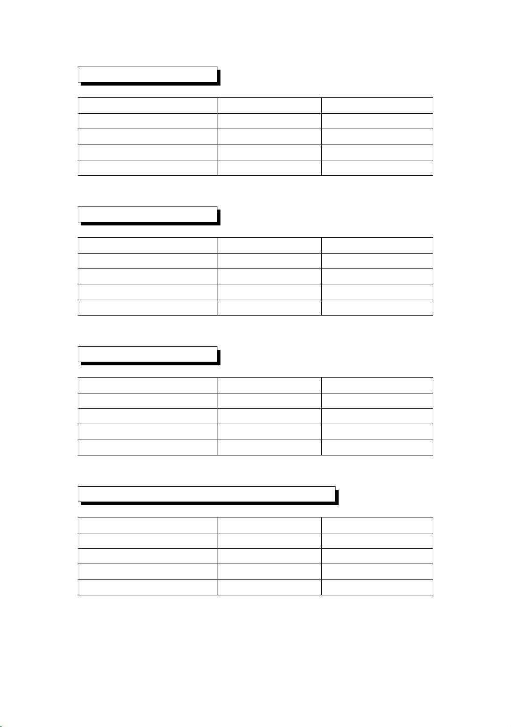
Active (Real) Power
Range Resolution Accuracy
0.000 to 9.999 KW *0.001/0.01/0.1 KW ± (1%+0.008KW)
10.00 to 99.99 KW *0.01/0.1 KW ± (1%+0.08KW)
100.0 to 999.9 KW 0.1 KW ±(1%+0.8KW)
1.000 to 9.999 MW 0.001 MW ± (1%+0.008MW)
* : The resolution is changed according the different ACA range.
Apparent Power
Range Resolution Accuracy
0.000 to 9.999 KVA *0.001/0.01/0.1KVA ± (1%+0.008KVA)
10.00 to 99.99 KVA *0.01/0.1 KVA ± (1%+0.08KVA)
100.0 to 999.9 KVA 0.1 KVA ± (1%+0.8KVA)
1.000 to 9.999 MVA 0.001 MVA ± (1%+0.008MVA)
* : The resolution is changed according the different ACA range.
Reactive Power
Range Resolution Accuracy
0.000 to 9.999 KVAR *0.001/0.01/0.1KVAR ± (1%+0.008 KVAR)
10.00 to 99.99 KVAR *0.01/0.1 KVAR ± (1%+0.08 KVAR)
100.0 to 999.9 KVAR 0.1 KVAR ±(1%+0.8 KVAR)
1.000 to 9.999 MVAR 0.001 MVAR ± (1%+0.008 MVAR)
* : The resolution is changed according the different ACA range.
Watt Hour ( Active Power Hour) : WH
Range Resolution Accuracy
0.000 to 9.999 KWH 0.001 KWH ± (2%+0.008 KWH)
10.00 to 99.99 KWH 0.01 KWH ± (2%+0.08 KWH)
100.0 to 999.9 KWH 0.1 KWH ±(2%+0.8 KWH)
1.000 to 9.999 MWH 0.001 MWH ± (2%+0.008 MWH)
7
Page 12
VA Hour ( Apparent Power Hour ) : SH
Range Resolution Accuracy
0.000 to 9.999 KVAH 0.001 KVAH ± (2%+0.008 KVAH)
10.00 to 99.99 KVAH 0.01 KVAH ± (2%+0.08 KVAH)
100.0 to 999.9 KVAH 0.1 KVAH ±(2%+0.8 KVAH)
1.000 to 9.999 MVAH 0.001 MVAH ± (2%+0.008 MVAH)
VAR Hour ( Reactive Power Hour ) : QH
Range Resolution Accuracy
0.000 to 9.999 KVARH 0.001 KVARH ± (2%+0.008 KVARH)
10.00 to 99.99 KVARH 0.01 KVARH ± (2%+0.08 KVARH)
100.0 to 999.9 KVARH 0.1 KVARH ±(2%+0.8 KVARH)
1.000 to 9.999 MVARH 0.001 MVARH ± (2%+0.008 MVARH)
Harmonics of AC voltage in Magnitude
* Fundamental frequency 50 Hz, 60 Hz
Range Resolution Accuracy
1 to 20th ± ( 2 % + 0.5 V )
21 to 30th 0.1 V ± ( 4 % + 0.5 V )
31 to 50th reference
Harmonics of AC voltage in Percentage
* Fundamental frequency 50 Hz, 60 Hz
Range Resolution Accuracy
1 to 20th ± ( 2 % + 10 d )
21 to 30th 0.1 % ± ( 4 % + 20 d )
31 to 50th reference
Harmonics of AC current in Magnitude
* Fundamental frequency 50 Hz, 60 Hz
Range Resolution Accuracy
1 to 20th ± ( 2 % + 0.5 A )
21 to 30th 0.1 A ± ( 4 % + 0.5 A )
31 to 50th reference
8
Page 13
Harmonics of AC current in Percentage
* Fundamental frequency 50 Hz, 60 Hz
Range Resolution Accuracy
1 to 20th ± ( 2 % + 10 d )
21 to 30th 0.1 % ± ( 4 % + 20 d )
31 to 50th reference
Peak value of ACV or ACA
Range Sample Time Accuracy
50 Hz 19 us ± ( 5 % + 30 d )
60 Hz 16 us
* us = micro seconds
Crest Factor of ACV or ACA
Range Resolution Accuracy
1.000 - 9.999 0.001 ± ( 5 % + 0.3 )
Total Harmonic Distortion
Range Resolution Accuracy
0 to 20 % 0.1 % ± ( 2 % + 5 d )
20.1 to 100 % ± ( 6 % + 10 d )
9
Page 14
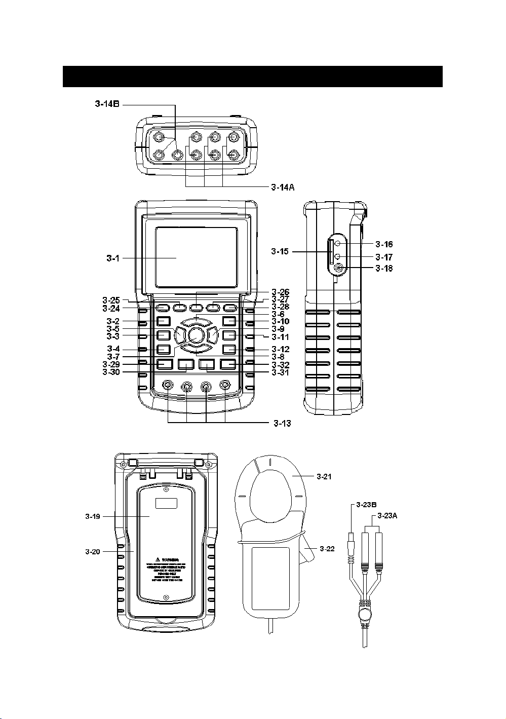
3. FRONT PANEL DESCRIPTION
10
Fig. 1
Page 15

3-1 Display
3-2 1Φ 3Φ ( Phase/wire ) key button
3-3 key button▲
3-4 key button▼
3-5 Hold key button
3-6 Backlight key button
3-7 Power key button
3-8 Exit key button
3-9 REC key button
3-10 A ( current ) range key button
3-11 Shift key button
3-12 Setup key button
3-13 Voltage input terminals
3-14A Current probe signal input sockets
3-14B Current probe power sockets
3-15 SD card socket
3-16 RS232 socket
3-17 Reset button
3-18 DC 9V power adapter socket
3-19 Battery Cover/Battery compartment
3-20 Stand
3-21 Current Sense Jaw
3-22 Trigger
3-23A Current probe signal plugs
3-23B Current probe power plug
11
Page 16

3-24 Harmonic Analysis Left Key
3-25 Harmonic Key
3-26 Harmonic Analysis Right Key
3-27 Harmonic Analysis V1,V2,V3, A1,A2,A3
Select Key
3-28 Harmonic Function Voltage or Current
Input Range
3-29 Power Measurement Key
3-30 Phase Diagram Key
3-31 Waveform of Voltage and Current Key
3-32 Transient Key
12
Page 17
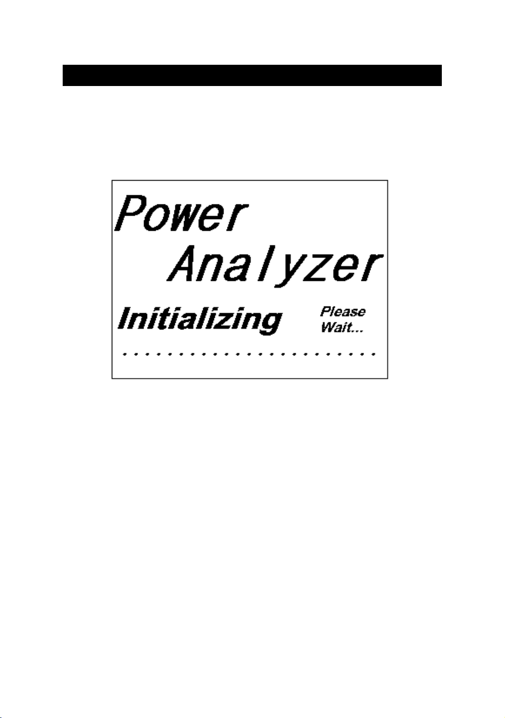
4. MEASURING PREPARATION
4-1 The original screen
4-2 Entry the measurement Screen
1)The bottom right display of screen 1 will show as " SD
Check " along with blinking while inserting SD CARD
then disappears after several seconds that indicates the
data from SD CARD has been read completed.
2)The bottom right display of screen 2 will show as " NO
DISK " along with blinking when SD CARD is not
inserted.
13
Page 18
screen 1 ( 4-2 )
Q
Q
V12: 0.0 V V1: 0.0 V A1: 0.00 A
V23: 0.0 V V2: 0.0 V A2: 0.00 A
V31: 0.0 V V3: 0.0 V A3: 0.00 A
P1: -0.000 KW S1: 0.000KVA Q1: -0.000 KVAR
P2: -0.000 KW S2: 0.000KVA Q2: -0.000 KVAR
P3: -0.000 KW S3: 0.000KVA Q3: -0.000 KVAR
PΣ : -0.000 KW SΣ : 0.000KVA
PF1: -0.00 PF 2: -0.00 PF 3: -0.00
PFΣ : 0.00 PF H: 0.00
Φ 1: - 0.0° Φ 2: - 0.0° Φ3: - 0.0°
WH: 0.000 KWH SH: 0.000KVAH
QH: 0.000 KVARH FREQ: 0.0 Hz
CP1201 SD
20A 3Φ 4W SEC: 2 CT: 1 PT: 1 Check
screen 2 ( 4-2 )
V12: 0.0 V V1: 0.0 V A1: 0.00 A
V23: 0.0 V V2: 0.0 V A2: 0.00 A
V31: 0.0 V V3: 0.0 V A3: 0.00 A
P1: -0.000 KW S1: 0.000KVA Q1: -0.000 KVAR
P2: -0.000 KW S2: 0.000KVA Q2: -0.000 KVAR
P3: -0.000 KW S3: 0.000KVA Q3: -0.000 KVAR
Σ :-0.000 KVAR
PΣ : -0.000 KW SΣ : 0.000KVA
PF1: -0.00 PF 2: -0.00 PF 3: -0.00
PFΣ : 0.00 PF H: 0.00
Φ 1: - 0.0° Φ 2: - 0.0° Φ3: - 0.0°
WH: 0.000 KWH SH: 0.000KVAH
QH: 0.000 KVARH FREQ: 0.0 Hz
CP1201 NO
20A 3Φ 4W SEC: 2 CT: 1 PT: 1 DISK
14
Σ :-0.000 KVAR
Page 19

4-3 The summary description of keyboard
1) POWER KEY ( 3-7, Fig. 1 ) :
Press the key to turn the instrument ON/OFF.
2) 1Φ 3Φ ( phase/wire ) KEY ( 3-2, Fig. 1 ) :
Press the key to select
(1P/2W、1P/3W、3P/3W、3P/4W) measurement
function mode.
3) A ( current ) RANGE KEY ( 3-10, Fig. 1 ) :
Press the key to change the current range quickly.
4) REC KEY ( 3-9, Fig. 1 ) :
The data record key for SD CARD.
5) HOLD KEY ( 3-5, Fig. 1 ) :
Press the key to freeze the display reading.
6) BACKLIGHT KEY ( 3-6, Fig. 1 ) :
Press the key to switch LCD backlight to ON/OFF.
7) SETUP KEY ( 3-12, Fig. 1 ) :
Press the key to setup the function before measuring.
8) EXIT KEY ( 3-8, Fig. 1 ) :
Press the key to exit setting screen.
9) SHIFT KEY ( 3-11, Fig. 1 )
Press the key to set the different functions in setting
screen.
10) UP ( ) KEY ( 3-3, Fig. 1 ) : ▲
Press the key to move the cursor up in setting
screen.
11) DOWN ( ) KEY ( 3-4, Fig. 1 ) :▼
Press the key to move the cursor down in setting
screen.
12) Harmonic Analysis Left Key ( 3-24, Fig. 1 )
13) Harmonic Key ( 3-25, Fig. 1)
14) Harmonic Analysis Right Key ( 3-26 , Fig. 1 )
15) Harmonic Analysis V1,V2,V3, A1,A2,A3
Select Key ( 3-27, Fig. 1 )
16) Harmonic Function Voltage or Current
Input Range Select Key ( 3-28, Fig. 1 )
17) Power Measurement Key ( 3-29, Fig. 1 )
18) Phase Diagram Key ( 3-30, Fig. 1 )
19) Waveform of Voltage and Current Key ( 3-31, Fig. 1)
20) Transient Key ( 3-32, Fig. 1)
15
Page 20
4-4 SETUP KEY description:
ling
T
l
l
A
A
T
l
Y
h
d
ling
T
l
A
A
T
l
Y
h
d
4-4-1 SHIFT KEY
* SHIFT 1 : When the symbols " SETUP " and " SHIFT 1 "
are appeared on up right display of screen 1 in the
meantime, and then use the or to select the▲▼
expect item.
* SHIFT 2 : When the symbols " SETUP " and " SHIFT 2 "
are appeared on up right display of screen 2 in the
meantime, and then use the ▲ or ▼ to select ( 1P/2W、
1P/3W、3P/3W、3P/4W ) in File Name function.
Folder Name: WTA01 SETUP
File Name: 3P401001.XLS SHIFT 1
REC Date: 2008-11-28 00:03:17
Samp
Delet File: 0 % SDVP : 10%
SD Format: 0 % Decima
Use Size: 388 KB C
Free Size: 1946 MB
otal Size: 1946 MB V Range: 200mV
PT: 1 : 1 V1 I1 P1
CT: 1 : 1 S1 Q1 PF1
Beep: ON Φ1 FREQ
Time: 2
rans Ref : 220.0 V
: Basic
amp Type: CP1201
Range: 200
RS232 Out Se
:
screen 1 ( 4-4 )
ear Mont
2010 11 13 14 37 25
Folder Name: WTA01 SETUP
File Name: 3P401001.XLS SHIFT 2
REC Date: 2008-11-28 00:03:17
Samp
De
SD Format: 0 % Decimal: Basic
Use Size: 388 KB Clamp Type: CP1201
Free Size: 1946 MB
otal Size: 1946 MB V Range: 200mV
PT: 1 : 1 V1 I1 P1
CT: 1 : 1 S1 Q1 PF1
Beep: ON Φ1 FREQ
ear Mont
2010 11 13 14 37 25
Time: 2
et File: 0 % SDVP : 10%
Date Hour Minute Secon
rans Ref : 220.0 V
Range: 200
RS232 Out Se
Date Hour Minute Secon
:
screen 2 ( 4-4 )
16
Page 21

4-4-2 The Setting Function menu
* Folder Name : Set the expect folder name for SD CARD,
the range is between WTA01 and WTA10.
* File Name: Set the file name for SD CARD, It allows setting
50 filenames in this function.
* REC Date: Show the recorded time of existing files
( Year/Month/Date, Hour/Min./Sec. )
* Sampling Time : Set the sampling time from 2 to 7200 seconds.
* Delete File : To delete the existing data from SD CARD.
* SD Format : to Format SD CARD fast.
* PT : Set the potential transformer from 1 to 1000.
* CT : Set the current transformer from 1 to 600.
* Beep : Set to ON/OFF for buzzer.
* Clamp Type : Select the Clamp Type to CP-1201, CP-200
CP-2000, CP-3000 or Other Type.
* RS232 out Sel. : Set RS232 output function, maximum up
to nine items can be selected to output. screen 1 screen 2.
* Year : Set the year.
* Month : Set the month.
* Date : Set the date.
* Hour : Set the hour.
* Minute : Set the minute.
* Second : Set the second.
4-5 Setting function description before measuring
Press SETUP KEY to enter setting function screen, the
selected item will be displayed in highlight.
17
Page 22
4-5-1 Folder Name: Set the folder name for SD
screen 1 ( 4-5-1 )
Folder Name: WTA01 SETUP
File Name: 3P401001.XLS
REC Date: 2008-11-28 00:03:17
Sampling Time: 2 Trans Ref : 220.0 V
Delet File: 0 % SDVP : 10%
SD Format: 0 % Decimal: Basic
Use Size: 388 KB Clamp Type: CP1201
Free Size: 1946 MB A Range: 200A
Total Size: 1946 MB V Range: 200mV
RS232 Out Sel:
PT: 1 : 1 V1 I1 P1
CT: 1 : 1 S1 Q1 PF1
Beep: ON Φ1 FREQ
Year Month Date Hour Minute Second
2010 12 05 11 14 49
screen 2 ( 4-5-1 )
Folder Name: WTA01 SETUP
File Name: 3P401001.XLS SHIFT 1
REC Date: 2008-11-28 00:03:17
Sampling Time: 2 Trans Ref : 220.0 V
Delet File: 0 % SDVP : 10%
SD Format: 0 % Decimal: Basic
Use Size: 388 KB Clamp Type: CP1201
Free Size: 1946 MB A Range: 200A
Total Size: 1946 MB V Range: 200mV
RS232 Out Sel:
PT: 1 : 1 V1 I1 P1
CT: 1 : 1 S1 Q1 PF1
Beep: ON Φ1 FREQ
Year Month Date Hour Minute Second
2010 12 05 11 14 34
18
Page 23
A : Folder Name range: WTA01 to WTA10.
B : Press or to select the expect folder number, the▲▼
number consists of " 01 to 10 " (as screen 1).
C : Press or continuously at least two seconds can▲▼
skip the numbers faster.
D : Press SHIFT KEY once, the symbol " SHIFT1" will
appear on up right display, and then press to entry next▼
setting function as screen 2 (Folder Name File Name).→
4-5-2 File Name: Set the file name for SD
A : The screen will show " NO File " indicator in REC Date
option when the selected file is new ( as screen 1 ).
B : The screen will show recording date and time in REC
Date option when the selected file has been recorded
as screen 2.
screen 1 ( 4-5-2 )
Folder Name: WTA03 SETUP
File Name: 3P401001.XLS
REC Date: NO File
Sampling Time: 2 Trans Ref : 220.0 V
Delet File: 0 % SDVP : 10%
SD Format: 0 % Decimal: Basic
Use Size: 388 KB Clamp Type: CP1201
Free Size: 1946 MB A Range: 200A
Total Size: 1946 MB V Range: 200mV
RS232 Out Sel:
PT: 1 : 1 V1 I1 P1
CT: 1 : 1 S1 Q1 PF1
Beep: ON Φ1 FREQ
Year Month Date Hour Minute Second
2010 11 13 14 37 25
19
Page 24
screen 2 ( 4-5-2 )
Folder Name: WTA01 SETUP
File Name: 3P401001.XLS
REC Date: 2008-11-28 00:03:17
Sampling Time: 2 Trans Ref : 220.0 V
Delet File: 0 % SDVP : 10%
SD Format: 0 % Decimal: Basic
Use Size: 388 KB Clamp Type: CP1201
Free Size: 1946 MB A Range: 200A
Total Size: 1946 MB V Range: 200mV
RS232 Out Sel:
PT: 1 : 1 V1 I1 P1
CT: 1 : 1 S1 Q1 PF1
Beep: ON Φ1 FREQ
Year Month Date Hour Minute Second
2010 12 05 11 15 31
C : File Name description : press or in screen 2 to▲▼
select expect file number from 001 to 050.
Remark : When press or > 2 sec, the setting ▲▼
no. will change fast.
* 1P201001 : 1P2 means one phase by two wires.
* 1P301001: 1P3 means one phase by three wires,
* 3P301001 : 3P3 means three phases by three wires.
* 3P401001 : 3P4 means three phases by four wires.
* HAR01001 : HAR means harmonic measurement.
* PHA01001 : PHA means phasor measurement.
* TRA01001 : TRA means transient measurement.
Remark :
Above file description, 01 means folder number,
001 means file number.
D : The up right display will show " SHIFT1 " symbol
while pressing SHIFT KEY once in screen 2, and then
press to enter next setting function as screen 3▼
( File Name Sampling Time ).→
20
Page 25
E : The up right display will show " SHIFT2 " symbol
while pressing SHIFT KEY again in screen 4, at this time
press ▲ or ▼ to select 1P/2W(1P2)、1P/3W(1P3)、
3P/3W(3P3) and 3P/4W(3P4) as screen 4.
F: One by one to press SHIFT KEY to select different
functions circularly.
Folder Name: WTA01 SETUP
File Name: 3P401001.XLS SHIFT 1
REC Date: 2008-11-28 00:03:17
Sampling Time: 2 Trans Ref : 220.0 V
Delet File: 0 % SDVP : 10% screen 3
SD Format: 0 % Decimal: Basic (4-5-2)
Use Size: 388 KB Clamp Type: CP1201
Free Size: 1946 MB A Range: 200A
Total Size: 1946 MB V Range: 200mV
RS232 Out Sel:
PT: 1 : 1 V1 I1 P1
CT: 1 : 1 S1 Q1 PF1
Beep: ON Φ1 FREQ
Year Month Date Hour Minute Second
2010 11 13 14 37 25
Folder Name: WTA01 SETUP
File Name: 3P401001.XLS SHIFT 2
REC Date: 2008-11-28 00:03:17
Sampling Time: 2 Trans Ref : 220.0 V screen 4
Delet File: 0 % SDVP : 10% ( 4-5-2 )
SD Format: 0 % Decimal: Basic
Use Size: 388 KB Clamp Type: CP1201
Free Size: 1946 MB A Range: 200A
Total Size: 1946 MB V Range: 200mV
RS232 Out Sel:
PT: 1 : 1 V1 I1 P1
CT: 1 : 1 S1 Q1 PF1
Beep: ON Φ1 FREQ
Year Month Date Hour Minute Second
2010 11 13 14 37 25
21
Page 26

4-5-3 Sampling time: Set the data logger sampling time
T
A
A
T
Y
T
A
A
T
Y
for SD
A : When press SHIFT KEY once, the symbol " SHIFT1 "
will disappear on up right display, at this time press
or to adjust expect sampling time as screen 2, ▲▼
adjusting numbers are from 2 to 7200 seconds.
Remark : When press or > 2 sec, the setting no. will change fast.▲▼
B : The up right display will show " SHIFT1 " symbol
while pressing SHIFT KEY again, and then press to▼
enter next setting function (Sampling Time Delete File)→
screen 1 ( 4-5-3 )
Folder Name: WTA01 SETUP
File Name: 3P401001.XLS SHIFT 1
REC Date: 2008-11-28 00:03:17
Sampling Time: 2
Delet File: 0 % SDVP : 10%
SD Format: 0 % Decimal: Basic
Use Size: 388 KB Clamp Type: CP1201
Free Size: 1946 MB
otal Size: 1946 MB V Range: 200mV
PT: 1 : 1 V1 I1 P1
CT: 1 : 1 S1 Q1 PF1
Beep: ON Φ1 FREQ
rans Ref : 220.0 V
Range: 200
RS232 Out Sel:
ear Month Date Hour Minute Second
2010 11 13 14 37 25
screen 2 ( 4-5-3 )
Folder Name: WTA01 SETUP
File Name: 3P401001.XLS
REC Date: 2008-11-28 00:03:17
Sampling Time: 2
Delet File: 0 % SDVP : 10%
SD Format: 0 % Decimal: Basic
Use Size: 388 KB Clamp Type: CP1201
Free Size: 1946 MB
otal Size: 1946 MB V Range: 200mV
PT: 1 : 1 V1 I1 P1
CT: 1 : 1 S1 Q1 PF1
Beep: ON Φ1 FREQ
ear Month Date Hour Minute Second
2010 11 13 14 37 25
rans Ref : 220.0 V
Range: 200
RS232 Out Sel:
22
Page 27
4-5-4 Delete File: Delete the files for SD
A : The indicator " Y or N " will appear on right side
display of the option while pressing SHIFT KEY
continuously at least two seconds, and now press ▲
the display will show " Y " in highlight as screen 2,
press SETUP KEY again to confirm, the selected file (ex:
3P401001.XLS) will be erased then return to screen 1,
or else press SETUP KEY in " N " option to return
to screen 1.
B : Press in screen 1 to enter next setting function▼
(Delete File SD Format)→
screen 1 ( 4-5-4 )
Folder Name: WTA01 SETUP
File Name: 3P401001.XLS SHIFT 1
REC Date: 2008-11-28 00:03:17
Sampling Time: 2 Trans Ref : 220.0 V
Delete File: 0 % SDVP : 10%
SD Format: 0 % Decimal: Basic
Use Size: 388 KB Clamp Type: CP1201
Free Size: 1946 MB A Range: 200A
Total Size: 1946 MB V Range: 200mV
RS232 Out Sel:
PT: 1 : 1 V1 I1 P1
CT: 1 : 1 S1 Q1 PF1
Beep: ON Φ1 FREQ
Year Month Date Hour Minute Second
2010 11 13 14 37 25
23
Page 28
screen 2 ( 4-5-4 )
Folder Name: WTA01 SETUP
File Name: 3P401001.XLS SHIFT 1
REC Date: 2008-11-28 00:03:17
Sampling Time: 2 Trans Ref : 220.0 V
Delete File: Y OR N SDVP : 10%
SD Format: 0 % Decimal: Basic
Use Size: 388 KB Clamp Type: CP1201
Free Size: 1946 MB A Range: 200A
Total Size: 1946 MB V Range: 200mV
RS232 Out Sel:
PT: 1 : 1 V1 I1 P1
CT: 1 : 1 S1 Q1 PF1
Beep: ON Φ1 FREQ
Year Month Date Hour Minute Second
2010 11 13 14 37 25
4-5-5 SD Format : Formatting function for SD CARD
A : The indicator " Y or N " will appear on right side
display of the option while pressing SHIFT KEY
continuously at least two seconds, and press the▲
display will show " Y " in highlight as screen 2,
press SETUP KEY again to confirm to format SD CARD
then return to screen 1, or else press SETUP KEY in
" N " option return to screen 1.
B : Press in screen 1 to enter next setting function ( SD▼
Format PT ).→
24
Page 29
screen 1 ( 4-5-5 )
Folder Name: WTA01 SETUP
File Name: 3P401001.XLS SHIFT 1
REC Date: 2008-11-28 00:03:17
Sampling Time: 2 Trans Ref : 220.0 V
Delete File: 0 % SDVP : 10%
SD Format: 0 % Decimal: Basic
Use Size: 388 KB Clamp Type: CP1201
Free Size: 1946 MB A Range: 200A
Total Size: 1946 MB V Range: 200mV
RS232 Out Sel:
PT: 1 : 1 V1 I1 P1
CT: 1 : 1 S1 Q1 PF1
Beep: ON Φ1 FREQ
Year Month Date Hour Minute Second
2010 11 13 14 37 25
screen 2 ( 4-5-5 )
Folder Name: WTA01 SETUP
File Name: 3P401001.XLS SHIFT 1
REC Date: 2008-11-28 00:03:17
Sampling Time: 2 Trans Ref : 220.0 V
Delete File: 0 % SDVP : 10%
SD Format: Y OR N Decimal: Basic
Use Size: 388 KB Clamp Type: CP1201
Free Size: 1946 MB A Range: 200A
Total Size: 1946 MB V Range: 200mV
RS232 Out Sel:
PT: 1 : 1 V1 I1 P1
CT: 1 : 1 S1 Q1 PF1
Beep: ON Φ1 FREQ
Year Month Date Hour Minute Second
2010 11 13 14 37 25
25
Page 30
4-5-6 PT: Set the Potential Transformer
A : When press SHIFT KEY once, the symbol " SHIFT1 "
will disappear as screen 2 at this time press or can▲▼
adjust to expect PT values, the adjusting numbers are
from 1 to 1000.
Remark : When press or > 2 sec, the setting ▲▼
no. will change fast.
B : Press SHIFT KEY once again will return to screen 1
then press to enter next setting function ( PT CT ).▼→
screen 1 ( 4-5-6 )
Folder Name: WTA01 SETUP
File Name: 3P401001.XLS SHIFT 1
REC Date: 2008-11-28 00:03:17
Sampling Time: 2 Trans Ref : 220.0 V
Delete File: 0 % SDVP : 10%
SD Format: 0 % Decimal: Basic
Use Size: 388 KB Clamp Type: CP1201
Free Size: 1946 MB A Range: 200A
Total Size: 1946 MB V Range: 200mV
RS232 Out Sel:
PT: 1 : 1 V1 I1 P1
CT: 1 : 1 S1 Q1 PF1
Beep: ON Φ1 FREQ
Year Month Date Hour Minute Second
2010 11 13 14 37 25
26
Page 31
screen 2 ( 4-5-6 )
Folder Name: WTA01 SETUP
File Name: 3P401001.XLS
REC Date: 2008-11-28 00:03:17
Sampling Time: 2 Trans Ref : 220.0 V
Delete File: 0 % SDVP : 10%
SD Format: 0 % Decimal: Basic
Use Size: 388 KB Clamp Type: CP1201
Free Size: 1946 MB A Range: 200A
Total Size: 1946 MB V Range: 200mV
RS232 Out Sel:
PT: 1 : 1 V1 I1 P1
CT: 1 : 1 S1 Q1 PF1
Beep: ON Φ1 FREQ
Year Month Date Hour Minute Second
2010 11 13 14 37 25
4-5-7 CT: Set the Current Transformer
A : When press SHIFT KEY once, the symbol " SHIFT1 "
will disappear as screen 2 at this time press or can▲▼
adjust to expect CT values, the adjusting numbers are
from 1 to 600.
Remark : When press or > 2 sec, the setting ▲▼
no. will change fast.
B : Press SHIFT KEY once again will return to screen 1
then press to enter next setting function ( CT ▼→
BEEP ). again will return to screen 1 then press to▼
enter next setting function ( CT BEEP ).→
27
Page 32
screen 1 ( 4-5-7 )
Folder Name: WTA01 SETUP
File Name: 3P401001.XLS SHIFT 1
REC Date: 2008-11-28 00:03:17
Sampling Time: 2 Trans Ref : 220.0 V
Delete File: 0 % SDVP : 10%
SD Format: 0 % Decimal: Basic
Use Size: 388 KB Clamp Type: CP1201
Free Size: 1946 MB A Range: 200A
Total Size: 1946 MB V Range: 200mV
RS232 Out Sel:
PT: 1 : 1 V1 I1 P1
CT: 1 : 1 S1 Q1 PF1
Beep: ON Φ1 FREQ
Year Month Date Hour Minute Second
2010 11 13 14 37 25
screen 2 ( 4-5-7 )
Folder Name: WTA01 SETUP
File Name: 3P401001.XLS
REC Date: 2008-11-28 00:03:17
Sampling Time: 2 Trans Ref : 220.0 V
Delete File: 0 % SDVP : 10%
SD Format: 0 % Decimal: Basic
Use Size: 388 KB Clamp Type: CP1201
Free Size: 1946 MB A Range: 200A
Total Size: 1946 MB V Range: 200mV
RS232 Out Sel:
PT: 1 : 1 V1 I1 P1
CT: 1 : 1 S1 Q1 PF1
Beep: ON Φ1 FREQ
Year Month Date Hour Minute Second
2010 11 13 14 37 25
28
Page 33
4-5-8 Beep: Control the buzzer to ON/OFF
A : When press SHIFT KEY once the symbol " SHIFT1 " will
disappear as screen 2, at this time press or to ▲▼
control the buzzer to ON/OFF.
B : Press SHIFT KEY once again will return to screen 1 then
press to enter next setting function ( BEEP Trans Ref▼→
type )
screen 1 ( 4-5-8 )
Folder Name: WTA01 SETUP
File Name: 3P401001.XLS SHIFT 1
REC Date: 2008-11-28 00:03:17
Sampling Time: 2 Trans Ref : 220.0 V
Delete File: 0 % SDVP : 10%
SD Format: 0 % Decimal: Basic
Use Size: 388 KB Clamp Type: CP1201
Free Size: 1946 MB A Range: 200A
Total Size: 1946 MB V Range: 200mV
RS232 Out Sel:
PT: 1 : 1 V1 I1 P1
CT: 1 : 1 S1 Q1 PF1
Beep: ON Φ1 FREQ
Year Month Date Hour Minute Second
2010 11 13 14 37 25
29
Page 34
screen 2 ( 4-5-8 )
Folder Name: WTA01 SETUP
File Name: 3P401001.XLS
REC Date: 2008-11-28 00:03:17
Sampling Time: 2 Trans Ref : 220.0 V
Delete File: 0 % SDVP : 10%
SD Format: 0 % Decimal: Basic
Use Size: 388 KB Clamp Type: CP1201
Free Size: 1946 MB A Range: 200A
Total Size: 1946 MB V Range: 200mV
RS232 Out Sel:
PT: 1 : 1 V1 I1 P1
CT: 1 : 1 S1 Q1 PF1
Beep: ON Φ1 FREQ
Year Month Date Hour Minute Second
2010 11 13 14 37 25
4-5-9 Trans Ref: Nominal voltage for
transient detection reference
A : When press SHIFT KEY once will disappear as screen 2,
at this time press or to adjsut the voltage level ▲▼
to 50.0 V to 850.0 V.
B : Press SHIFT KEY once again will return to screen 1 then
press to enter next setting function ( Trans Ref ▼→
SDVP ).
30
Page 35
screen 1 ( 4-5-9 )
Folder Name: WTA01 SETUP
File Name: 3P401001.XLS SHIFT 1
REC Date: NO File
Sampling Time: 2 Trans Ref : 220.0 V
Delete File: 0 % SDVP : 10%
SD Format: 0 % Decimal: Basic
Use Size: 23 MB Clamp Type: CP1201
Free Size: 1904 MB A Range: 200A
Total Size: 1927 MB V Range: 200mV
RS232 Out Sel:
PT: 1 : 1 V1 I1 P1
CT: 1 : 1 S1 Q1 PF1
Beep: ON Φ1 FREQ
Year Month Date Hour Minute Second
2010 12 14 09 22 41
screen 2 ( 4-5-9 )
Folder Name: WTA01 SETUP
File Name: 3P401001.XLS
REC Date: NO File
Sampling Time: 2 Trans Ref : 220.0 V
Delete File: 0 % SDVP : 10%
SD Format: 0 % Decimal: Basic
Use Size: 23 MB Clamp Type: CP1201
Free Size: 1904 MB A Range: 200A
Total Size: 1927 MB V Range: 200mV
RS232 Out Sel:
PT: 1 : 1 V1 I1 P1
CT: 1 : 1 S1 Q1 PF1
Beep: ON Φ1 FREQ
Year Month Date Hour Minute Second
2010 12 14 09 22 41
31
Page 36
4-5-10 SDVP: Set up upper and low limits
% of transient voltage detection
A : When press SHIFT KEY once will disappear as screen 2,
at this time press or to adjsut the voltage % value▲▼
to 1% to 100%.
B : Press SHIFT KEY once again will return to screen 1 then
press to enter next setting function ( SDVP ▼→
Decimal ).
screen 1 ( 4-5-10 )
Folder Name: WTA01 SETUP
File Name: 3P401026.XLS SHIFT 1
REC Date: NO File
Sampling Time: 2 Trans Ref : 220.0 V
Delete File: 0 % SDVP : 10%
SD Format: 0 % Decimal: Basic
Use Size: 23 MB Clamp Type: CP1201
Free Size: 1904 MB A Range: 200A
Total Size: 1927 MB V Range: 200mV
RS232 Out Sel:
PT: 1 : 1 V1 I1 P1
CT: 1 : 1 S1 Q1 PF1
Beep: ON Φ1 FREQ
Year Month Date Hour Minute Second
2010 12 14 09 22 41
32
Page 37
screen 2 ( 4-5-10 )
Folder Name: WTA01 SETUP
File Name: 3P401026.XLS
REC Date: NO File
Sampling Time: 2 Trans Ref : 220.0 V
Delete File: 0 % SDVP : 10%
SD Format: 0 % Decimal: Basic
Use Size: 23 MB Clamp Type: CP1201
Free Size: 1904 MB A Range: 200A
Total Size: 1927 MB V Range: 200mV
RS232 Out Sel:
PT: 1 : 1 V1 I1 P1
CT: 1 : 1 S1 Q1 PF1
Beep: ON Φ1 FREQ
Year Month Date Hour Minute Second
2010 12 14 09 22 41
4-5-11 Decimal Type: set the Decimal type to
Basic ( .) or Euro ( , )
The numerical data structure of SD card
is default used the " . " as the decimal,
for example "20.6" "1000.53" . But in
certain countries ( Europe ...) is used
the " , " as the decimal point, for
example " 20,6 " "1000,53". Under such
situation, it should change the Decimal
character at first.
A : When press SHIFT KEY once the symbol " SHIFT1 " will
disappear as screen 2, at this time press or to select▲▼
the Decimal type to " Basic " or " Euro ".
33
Page 38

* Basic type :
The numerical data structure of SD card
is default used the " . " as the decimal,
for example "20.6" "1000.53" .
* Euro type :
The numerical data structure of SD card
is default used the " , " as the decimal,
for example "20,6" "1000,53" .
B : Press SHIFT KEY once again will return to screen 1 then
press to enter next setting function ( Decimal type ▼→
Clamp type ).
screen 1 ( 4-5-11 )
Folder Name: WTA01 SETUP
File Name: 3P401001.XLS SHIFT 1
REC Date: 2008-11-28 00:03:17
Sampling Time: 2 Trans Ref : 220.0 V
Delete File: 0 % SDVP : 10%
SD Format: 0 % Decimal: Basic
Use Size: 388 KB Clamp Type: CP1201
Free Size: 1946 MB A Range: 200A
Total Size: 1946 MB V Range: 200mV
RS232 Out Sel:
PT: 1 : 1 V1 I1 P1
CT: 1 : 1 S1 Q1 PF1
Beep: ON Φ1 FREQ
Year Month Date Hour Minute Second
2010 11 13 14 37 25
34
Page 39
screen 2 ( 4-5-11 )
Folder Name: WTA01 SETUP
File Name: 3P401001.XLS
REC Date: 2008-11-28 00:03:17
Sampling Time: 2 Trans Ref : 220.0 V
Delete File: 0 % SDVP : 10%
SD Format: 0 % Decimal: Basic
Use Size: 388 KB Clamp Type: CP1201
Free Size: 1946 MB A Range: 200A
Total Size: 1946 MB V Range: 200mV
RS232 Out Sel:
PT: 1 : 1 V1 I1 P1
CT: 1 : 1 S1 Q1 PF1
Beep: ON Φ1 FREQ
Year Month Date Hour Minute Second
2010 11 13 14 37 25
4-5-12 Clamp Type: set the clamp type to
Lutron Clamp or other Clamp
A : When press SHIFT KEY once the symbol " SHIFT1 " will
be disappeared and show as screen 2, at this time press
or to select the Lutron standard clamp or other ▲▼
Clamp ( CP-200, CP-1201, CP-2000. CP-3000, Other ).
B : When select the different Clamp type, the V range
and the A range will show the corresponding value.
C : Press SHIFT KEY once again will return to screen 1 then
press to enter next setting function ( Clamp Type ▼→
A range ).
35
Page 40
screen 1 ( 4-5-12 )
Folder Name: WTA01 SETUP
File Name: 3P401001.XLS SHIFT 1
REC Date: 2008-11-28 00:03:17
Sampling Time: 2 Trans Ref : 220.0 V
Delete File: 0 % SDVP : 10%
SD Format: 0 % Decimal: Basic
Use Size: 388 KB Clamp Type: CP1201
Free Size: 1946 MB A Range: 200A
Total Size: 1946 MB V Range: 200mV
RS232 Out Sel:
PT: 1 : 1 V1 I1 P1
CT: 1 : 1 S1 Q1 PF1
Beep: ON Φ1 FREQ
Year Month Date Hour Minute Second
2010 11 13 14 37 25
screen 2 ( 4-5-12 )
Folder Name: WTA01 SETUP
File Name: 3P401001.XLS
REC Date: 2008-11-28 00:03:17
Sampling Time: 2 Trans Ref : 220.0 V
Delete File: 0 % SDVP : 10%
SD Format: 0 % Decimal: Basic
Use Size: 388 KB Clamp Type: CP1201
Free Size: 1946 MB A Range: 200A
Total Size: 1946 MB V Range: 200mV
RS232 Out Sel:
PT: 1 : 1 V1 I1 P1
CT: 1 : 1 S1 Q1 PF1
Beep: ON Φ1 FREQ
Year Month Date Hour Minute Second
2010 11 13 14 37 25
36
Page 41
4-5-13 A range Setting ( Current range Setting )
A
A : When press SHIFT KEY once the symbol " SHIFT1 " will
be disappeared and show as screen 2, at this time press
or to select A range to 20A to 2000A or▲▼
30A to 3000A.
* The setting value should accoding your Clamp type.
* The CP-3000 clamp can set 30A, 300A, 3000A.
* The CP-2000 clamp can set 20A, 200A, 2000A.
* The CP-1201 clamp can set 20A, 200A, 1200A.
* The CP-200 clamp can set 20A, 200A.
* The Other clamp can set 20A, 200A, 2000A, 30
300A, 3000A.
Attention :
The meter's A range ( Current range ) value should
same as the Clamp's current selecting range value.
B : Press SHIFT KEY once again will return to screen 1 then
press to enter next setting function ( A Range ▼→
V range ).
screen 1 ( 4-5-13 )
Folder Name: WTA01 SETUP
File Name: 3P401001.XLS SHIFT 1
REC Date: 2008-11-28 00:03:17
Sampling Time: 2 Trans Ref : 220.0 V
Delete File: 0 % SDVP : 10%
SD Format: 0 % Decimal: Basic
Use Size: 388 KB Clamp Type: CP1201
Free Size: 1946 MB ARange: 200A
Total Size: 1946 MB V Range: 200mV
RS232 Out Sel:
PT: 1 : 1 V1 I1 P1
CT: 1 : 1 S1 Q1 PF1
Beep: ON Φ1 FREQ
Year Month Date Hour Minute Second
2010 11 13 14 37 25
37
Page 42
screen 2 ( 4-5-13 )
Folder Name: WTA01 SETUP
File Name: 3P401001.XLS
REC Date: 2008-11-28 00:03:17
Sampling Time: 2 Trans Ref : 220.0 V
Delete File: 0 % SDVP : 10%
SD Format: 0 % Decimal: Basic
Use Size: 388 KB Clamp Type: CP1201
Free Size: 1946 MB ARange: 200A
Total Size: 1946 MB V Range: 200mV
RS232 Out Sel:
PT: 1 : 1 V1 I1 P1
CT: 1 : 1 S1 Q1 PF1
Beep: ON Φ1 FREQ
Year Month Date Hour Minute Second
2010 11 13 14 37 25
4-5-14 V range Setting ( Voltage range Setting )
A : When press SHIFT KEY once the symbol " SHIFT1 " will
be disappeared and show as screen 2, at this time press
or to select V range to 200mV, 300mV, 500mV, ▲▼
1V, 2V, 3V.
* The setting function only available for the Other clamp.
* The V range value of CP-200, CP-1201, CP-2000,
CP-3000 will dfault to 200mV, it can not be adjusted.
B : Press SHIFT KEY once again will return to screen 1 then
press to enter next setting function ( A Range ▼→
RS232 OUT SEL ).
38
Page 43
screen 1 ( 4-5-14 )
Folder Name: WTA01 SETUP
File Name: 3P401001.XLS SHIFT 1
REC Date: 2008-11-28 00:03:17
Sampling Time: 2 Trans Ref : 220.0 V
Delete File: 0 % SDVP : 10%
SD Format: 0 % Decimal: Basic
Use Size: 388 KB Clamp Type: CP1201
Free Size: 1946 MB A Range: 200A
Total Size: 1946 MB VRange: 200mV
RS232 Out Sel:
PT: 1 : 1 V1 I1 P1
CT: 1 : 1 S1 Q1 PF1
Beep: ON Φ1 FREQ
Year Month Date Hour Minute Second
2010 11 13 14 37 25
screen 2 ( 4-5-14 )
Folder Name: WTA01 SETUP
File Name: 3P401001.XLS
REC Date: 2008-11-28 00:03:17
Sampling Time: 2 Trans Ref : 220.0 V
Delete File: 0 % SDVP : 10%
SD Format: 0 % Decimal: Basic
Use Size: 388 KB Clamp Type: CP1201
Free Size: 1946 MB A Range: 200A
Total Size: 1946 MB VRange: 200mV
RS232 Out Sel:
PT: 1 : 1 V1 I1 P1
CT: 1 : 1 S1 Q1 PF1
Beep: ON Φ1 FREQ
Year Month Date Hour Minute Second
2010 11 13 14 37 25
39
Page 44
4-5-15 RS232 Out Sel setting
A : When press SHIFT KEY continuously at least two
seconds as screen 2 and now press or to select▲▼
the item that intend to output, maximum up to nine
items, when the cursor stops on the selected item and
then press SETUP KEY again, the selected item will be
displayed in highlight.
B : Press SHIFT KEY it can change the screen page
from Screen 2 Screen 5.→
C : If the selected items are over nine, the low right
display will show indicator " full " as screen 6.
D : After the selecting is completed, press SHIFT KEY
continuously at least two seconds again will return to
screen 1 and show all the selected items at the same
time.
E : Press in screen 1 to enter next setting function▼
( RS232 Out Sel Year )→
screen 1 ( 4-5-15 )
Folder Name: WTA01 SETUP
File Name: 3P401001.XLS SHIFT 1
REC Date: 2008-11-28 00:03:17
Sampling Time: 2 Trans Ref : 220.0 V
Delete File: 0 % SDVP : 10%
SD Format: 0 % Decimal: Basic
Use Size: 388 KB Clamp Type: CP1201
Free Size: 1946 MB A Range: 200A
Total Size: 1946 MB V Range: 200mV
RS232 Out Sel:
PT: 1 : 1 V1 I1 P1
CT: 1 : 1 S1 Q1 PF1
Beep: ON Φ1 FREQ
Year Month Date Hour Minute Second
2010 11 13 14 37 25
40
Page 45
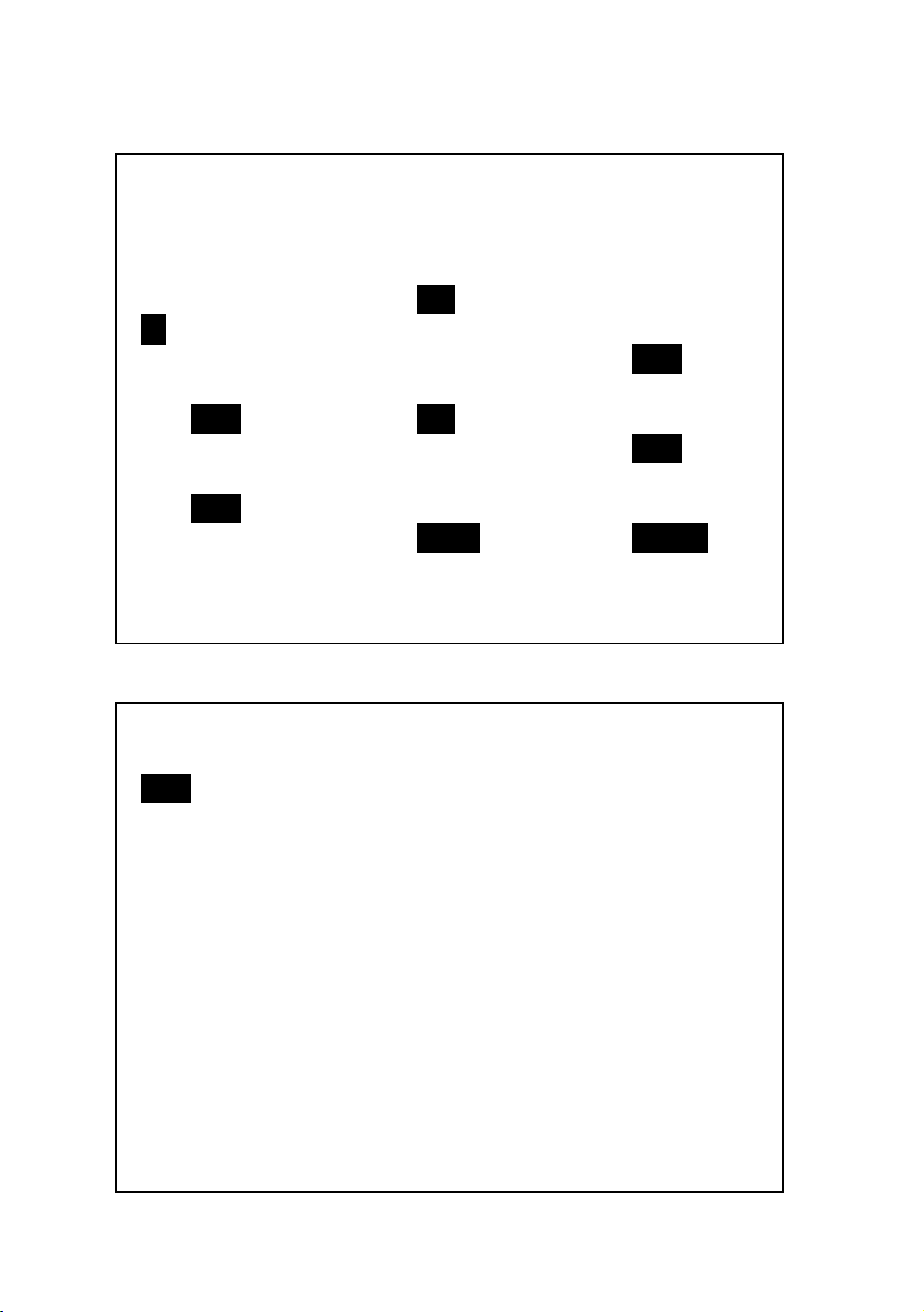
screen 2 ( 4-5-15 )
RS232 OUTPUT SELECT
1. V12 12. P3 23. PF2
2. V23 13. PΣ 24. PF3
3. V31 14. S1 25. PFΣ
4. V1 15. S2 26. PFH
5. V2 16. S3 27. Φ 1
6. V3 17. SΣ 28. Φ 2
7. I1 18. Q1 29. Φ 3
8. I2 19. Q2 30. WH
9. I3 20. Q3 31. SH
10. P1 21. QΣ 32. QH
11. P2 22. PF1 33. FREQ
screen 3 ( 4-5-15 )
RS232 OUTPUT SELECT
34. H01 45. H12 56 H23
35. H02 46. H13 57 H24
36. H03 47. H14 58 H25
37. H04 48. H15 59 H26
38. H05 49. H16 60 H27
39. H06 50. H17 61 H28
40. H07 51 H18 62 H29
41. H08 52 H19 63 H30
42. H09 53. H20 64 H31
43. H11 54. H21 65 H32
44. H01 55. H22 66 H33
41
Page 46
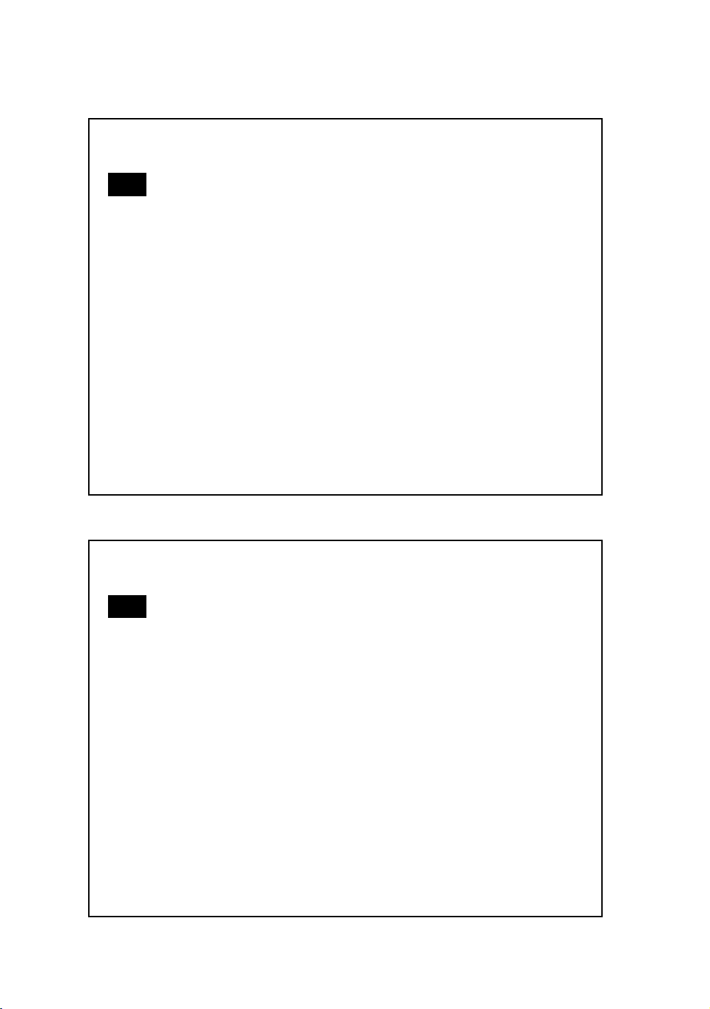
screen 4 ( 4-5-15 )
RS232 OUTPUT SELECT
67. H34 78. H45 89 Φ V12
68. H35 79. H46 90 Φ V23
69. H36 80 H47 91 Φ V31
70. H37 81. H48 92 Φ V1
71. H38 82. H49 93 Φ V2
72. H39 83. H50 94 Φ V3
73. H40 84. THD 95 Φ A1
74. H41 85. Vpp 96 Φ A2
75. H42 86. CFV 97 Φ A3
76. H43 87. App 98 AveV
77. H44 88 CFA 99 AveA
screen 5 ( 4-5-15 )
RS232 OUTPUT SELECT
100. Vn
101. An
102. dV
103. VUR
104. Vd0
105. Vd2
106. dA
107. AUR
108. Ad0
109. Ad2
42
Page 47
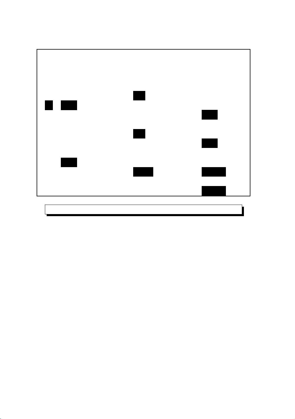
screen 6 ( 4-5-15 )
RS232 OUTPUT SELECT
1. V12 12. P3 23. PF2
2. V23 13. PΣ 24. PF3
3. V31 14. S1 25. PFΣ
4. V1 15. S2 26. PFH
5. V2 16. S3 27. Φ 1
6. V3 17. SΣ 28. Φ 2
7. I1 18. Q1 29. Φ 3
8. I2 19. Q2 30. WH
9. I3 20. Q3 31. SH
10. P1 21. QΣ 32. QH
11. P2 22. PF1 33. FREQ
FULL
4-5-16 Year/Month/Date/Hour/Minute/Second setting
A : When press SHIFT KEY once the symbol " SHIFT1"
will disappear as screen 2, at this time press or ▲▼
to adjust expect numbers, and press or ▲▼
continuously at least two seconds can skip the
numbers faster.
B : When press SHIFT KEY once, the symbol " SHIFT1"
will appear as screen 1, at this time press ▼
to enter next setting function ( Year Month ).→
C : The settings about ( Month Date ), (Date →→
Hour ), (Hour Minute ), ( Minute Second ) are→→
same as above step A and step B.
43
Page 48
D : In this setting function ( Year Minute ), press or→▲
in addition to adjust the numbers, and the setting▼
value will also be saved during the adjusting.
E : In the function of setting " second ", press or ▲▼
to adjust numbers. at this point the number of second
is at a standstill condition and then press setup key
that will save setting value and also start counting
function of " second ".
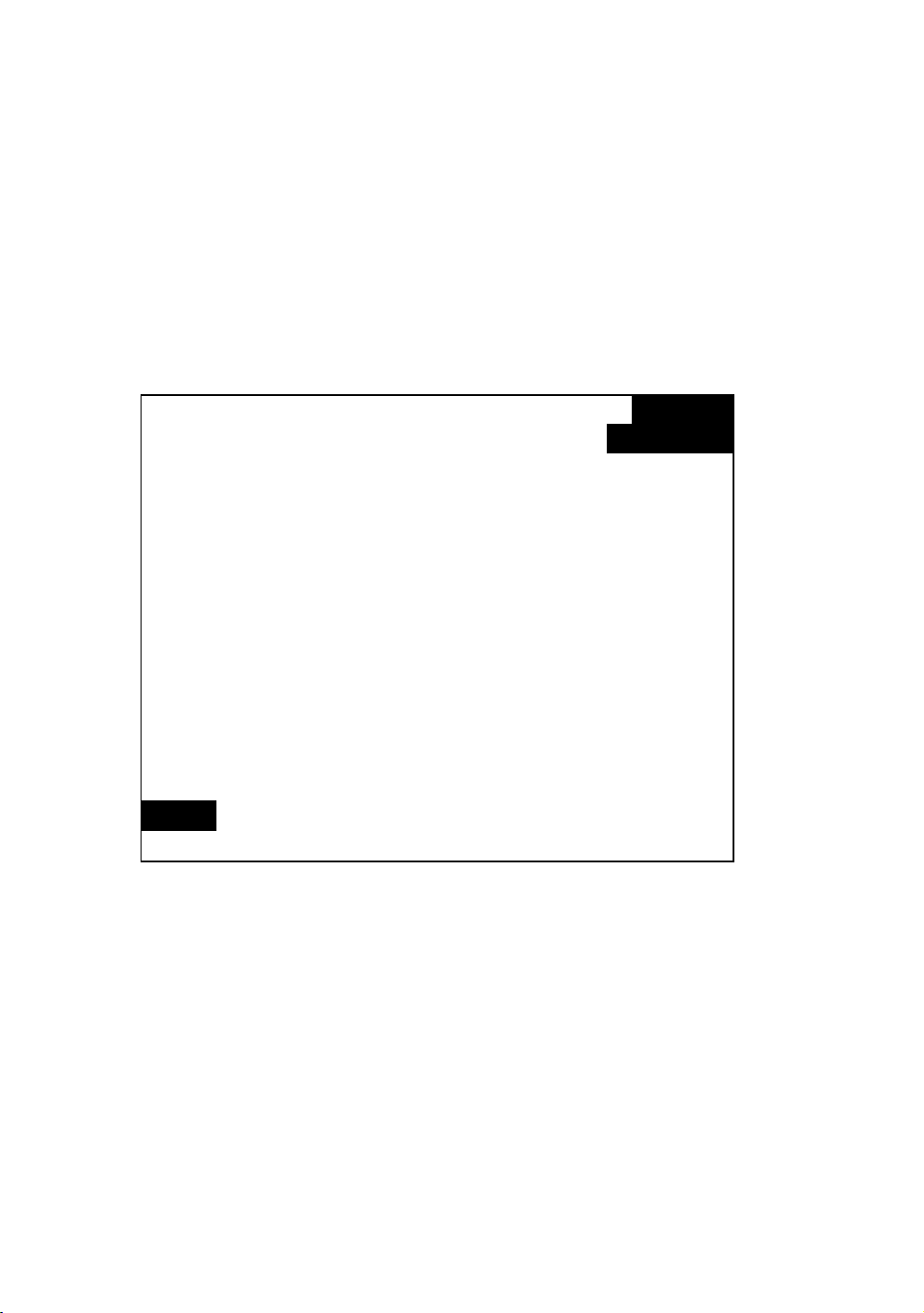
Folder Name: WTA01 SETUP
File Name: 3P401001.XLS SHIFT 1
REC Date: 2008-11-28 00:03:17
Sampling Time: 2 Trans Ref : 220.0 V screen 1
Delete File: 0 % SDVP : 10% ( 4-5-16 )
SD Format: 0 % Decimal: Basic
Use Size: 388 KB Clamp Type: CP1201
Free Size: 1946 MB A Range: 200A
Total Size: 1946 MB V Range: 200mV
RS232 Out Sel:
PT: 1 : 1 V1 I1 P1
CT: 1 : 1 S1 Q1 PF1
Beep: ON Φ1 FREQ
Year Month Date Hour Minute Second
2010 11 13 14 37 25
44
Page 49
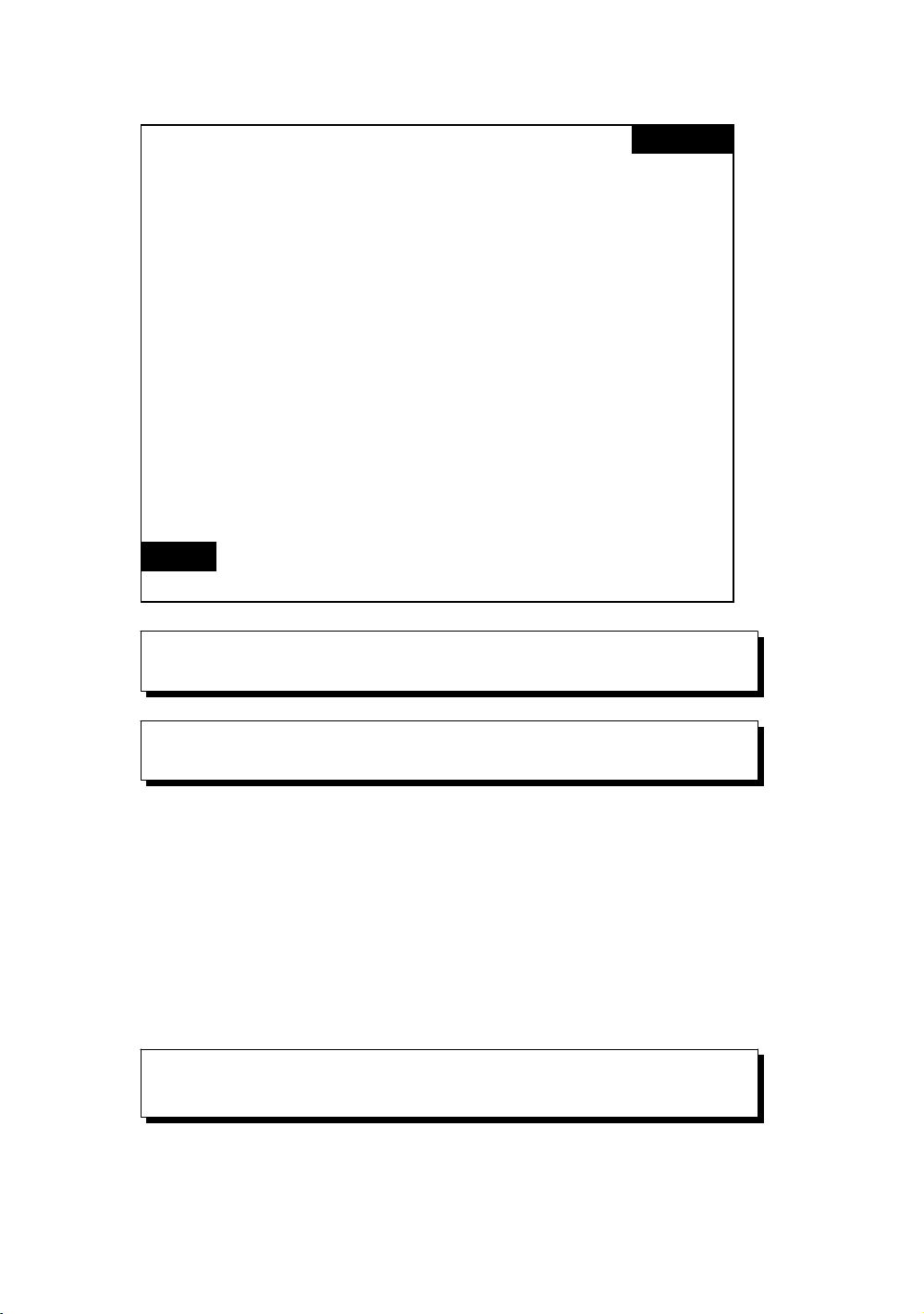
Folder Name: WTA01 SETUP
File Name: 3P401001.XLS
REC Date: 2008-11-28 00:03:17
Sampling Time: 2 Trans Ref : 220.0 V screen 2
Delete File: 0 % SDVP : 10% ( 4-5-16 )
SD Format: 0 % Decimal: Basic
Use Size: 388 KB Clamp Type: CP1201
Free Size: 1946 MB A Range: 200A
Total Size: 1946 MB V Range: 200mV
RS232 Out Sel:
PT: 1 : 1 V1 I1 P1
CT: 1 : 1 S1 Q1 PF1
Beep: ON Φ1 FREQ
Year Month Date Hour Minute Second
2010 11 13 14 37 25
4-5-17 When all settings are completed, press EXIT
KEY to return measuring screen.
4-5-18 The descriptions about SD CARD memory
space
A : Use Size - To show the space data numbers that have
been used.
B : Free Size - To show the data numbers of balance space.
C : Total Size - To show the data numbers of total space.
D : Typical SD CARD and SDHC both can be used with the
instrument, except the SD CARD memory size is less
than 32MB.
4-5-19 RESET KEY : Press this key to reboot the
instrument
45
Page 50
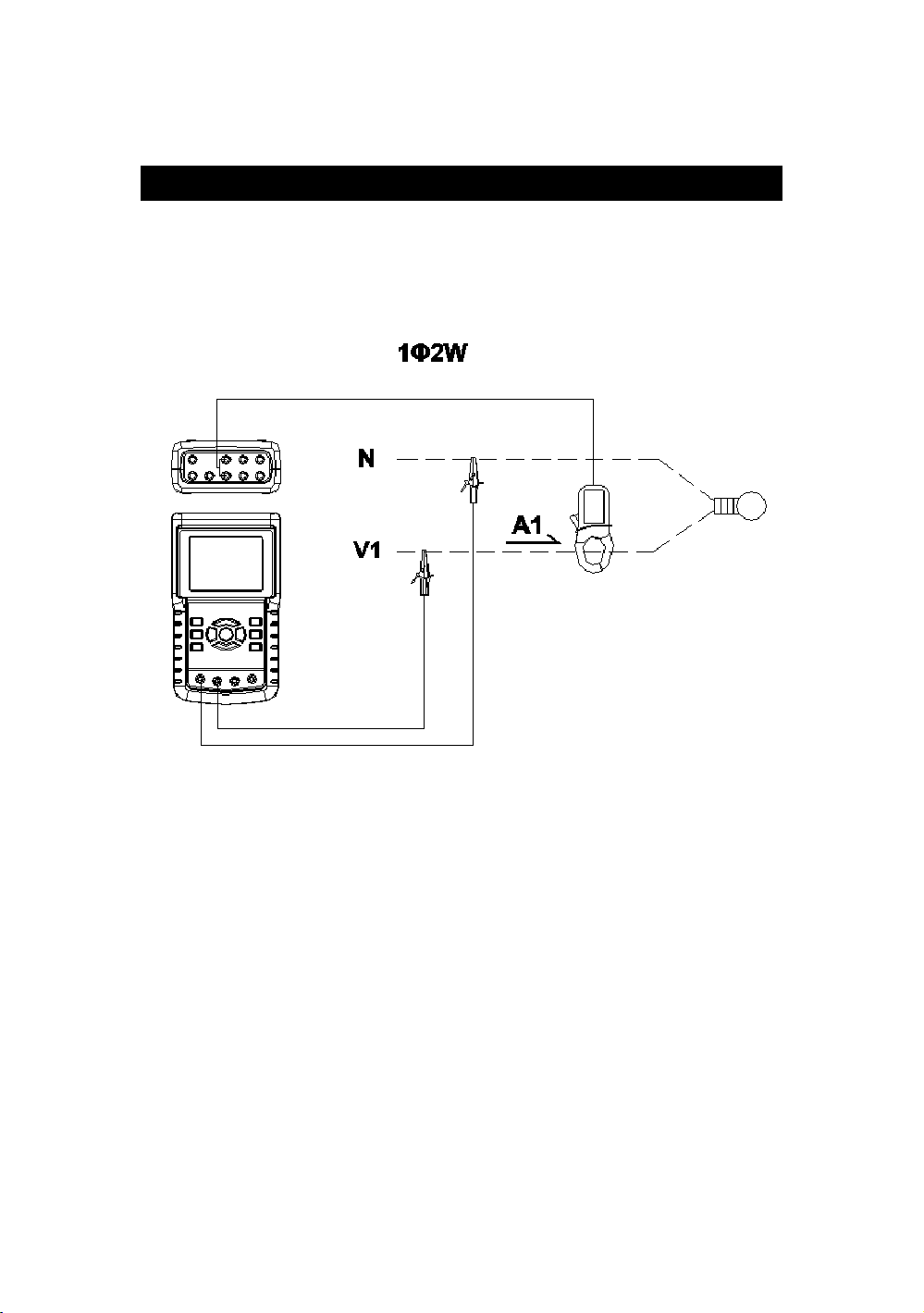
5. MEASURING PROCEDURES
5-1 1Φ 2W ( one phase by two wires ) measurement
A : Diagram
SCREEN 1 ( 5-1 )
B : Operation Instructions:
B-1 : Power on the instrument by pressing POWER
KEY, and then press 1Φ 3Φ KEY to select the 1Φ 2W
system, the selected name of system will be
appeared on bottom left display of screen 2.
B-2 : Connect the line voltage L1, Vn ( Neutral ) to
V1 and N terminals of the instrument.
B-3: Place the conductor of CP-1201 (A1)to A1 as
screen 1.
B-4: Connect the output of clamp meter " CP-1200(A1) "
to A1 terminal of the instrument.
B-5: The related measuring factors will be appeared on
display, about the instruction of factor please refer
appendix 1 ( 5-16, page 68 ).
46
Page 51
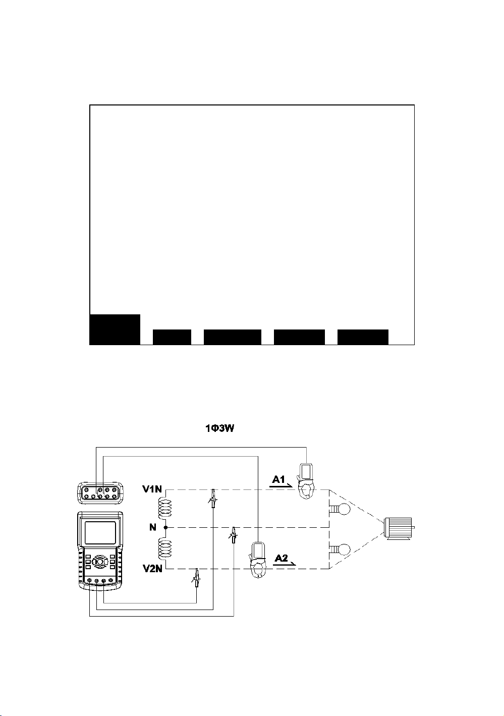
screen 2 ( 5-1 )
V1: 0.0 V
A1: 0.00 A
P 1 : - 0.000KW P F 1 : - 0.00
S 1 : 0.000KVA P F H : 0.00
Q 1 : - 0.000KVAR Φ 1 : - 0.0°
W H : 0.000KWH
S H : 0.000KVAH
Q H : 0.000KVARH F R E Q : 50.1 Hz
CP1201
20A 1Φ 2W SEC: 2 CT: 1 PT: 1
5-2 1Φ 3W (one phase by three wires) measurement
A : Diagram
screen1 ( 5-2 )
47
Page 52
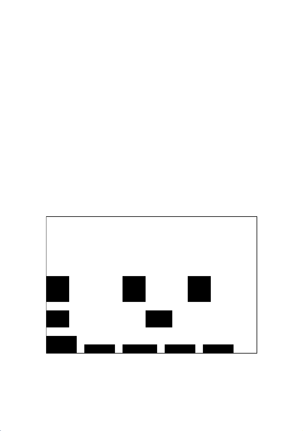
B : Operation Instructions:
B-1 : Power on the instrument by pressing POWER KEY,
and then press 1Φ 3Φ KEY to select the 1Φ 3W system,
the selected name of system will be appeared on bottom
left display of screen 2.
B-2 : Connect the line voltage L1, L2 and Vn (Neutral) to
V1, V2 and N terminals of the instrument.
B-3 : Place the conductor of CP-1201(A1), CP-1201(A2)
hook to A1 and A2 as screen 1.
B-4 : Connect the outputs of clamp meter
CP-1201(A1)、CP-1201(A2) to A1 and A2 terminals of
the instrument.
B-5 : The related measuring factors will be appeared on
display, about the instruction of factor please refer
appendix 1 ( 5-16, page 68 ).
screen 2 ( 5-2 )
V 1 : 0.0 V P 1 : - 0.000KW
V 2 : 0.0 V P 2 : - 0.000KW
A 1 : 0.00 A S 1 : 0.000KVA
A 2 : 0.00 A S 2 : 0.000KVA
Q 1 : - 0.000KVAR
Q 2 : - 0.000KVAR
PΣ : 0.000 KW SΣ : 0.000 KVA QΣ : 0.000 KVAR
PF1: -0.00 PF2: -0.00 PFΣ : 0.00
PFH: 0.00 Φ 1: -0.0° Φ2: -0.0°
WH: 0.000 KWH SH: 0.000 KVAH
QH: 0.000 KVARH FREQ: 50.0 Hz
CP1201
20A 1Φ 3W SEC: 2 CT: 1 PT: 1
48
Page 53
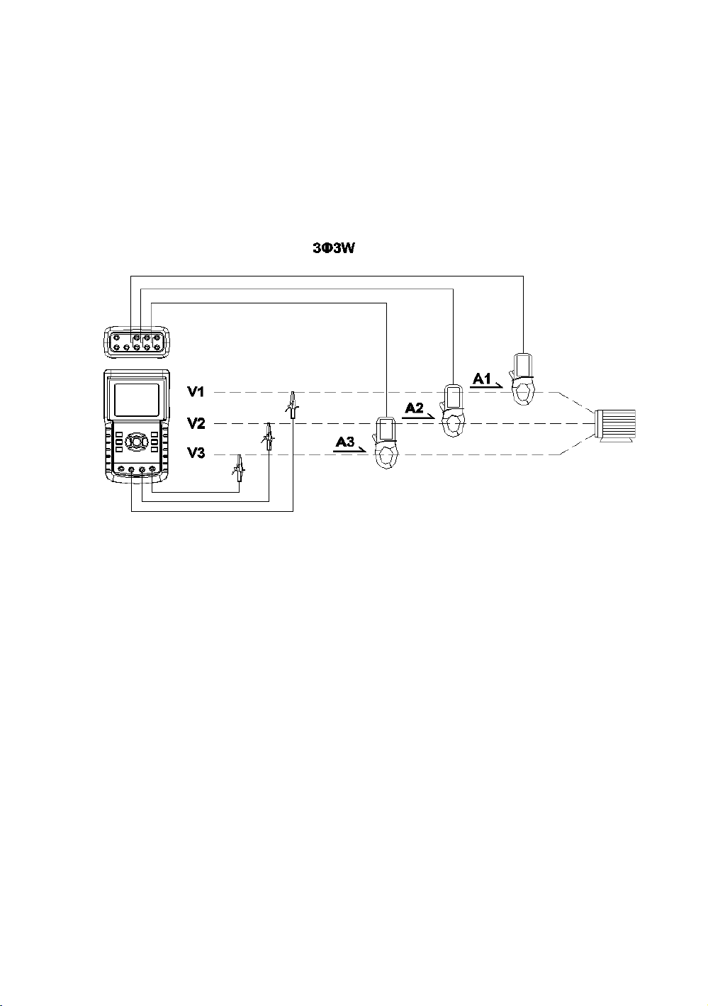
5-3 3Φ 3W (three phases by three wires)
measurement
A : Diagram
screen 1 ( 5-3 )
B : Operation Instructions:
B-1 : Power on the instrument by pressing POWER KEY,
and then press 1Φ 3Φ KEY to select the 3Φ 3W system,
the selected name of system will be appeared on bottom
left display of screen 2.
B-2: Connect the line voltage L1, L2 and L3 to V1, V2
and V3 terminals of the instrument.
B-3: Place the conductor of CP-1201(A1), CP-1201(A2),
CP-1201(A3) hook to A1, A2 ,A3 as screen 1.
B-4 : Connect the outputs of clamp meter CP-1201(A1)
, CP-1201(A2), CP-1201(A3) to A1, A2, A3 terminals
of the instrument.
B-5: The related measuring factors will be appeared on
display, about the instruction of factor please refer
appendix 1 ( 5-16, page 68 ).
49
Page 54
screen 2 ( 5-3 )
V12: 0.0 V A1: 0.00 A
V23: 0.0 V A2: 0.00 A
V31: 0.0 V A3: 0.00 A
P Σ : - 0.000 KW
S Σ : 0.000 KVA
Q Σ : 0.000 KVAR
PFΣ : 0.00 P F H : 0.00
WH: 0.000 KWH SH: 0.000 KVAH
QH: 0.000 KVARH FREQ: 50.0 Hz
CP1201
20A 3Φ 3W SEC: 2 CT: 1 PT: 1
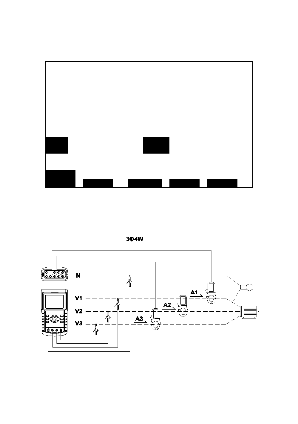
5-4 3Φ 4W (three phases by four wires)
measurement
A : Diagram
screen 1 ( 5-4 )
50
Page 55
B: Operation Instructions:
B-1 : Power on the instrument by pressing POWER KEY,
and then press 1Φ 3Φ KEY to select the 3Φ 4W system,
the selected name of system will be appeared on bottom
left display of screen 2.
B-2 : Connect the line voltage L1, L2, L3 and Vn to
V1, V2, V3 and N terminals of the instrument.
B-3 : Place the conductor of CP-1201(A1), CP-1201(A2)、
CP-1201(A3) hook to A1, A2, A3 as screen 1.
B-4 : Connect the outputs of clamp meter
CP-1201(A1), CP-1201(A2), CP-1201(A3) to
A1、A2、A3 terminals of the instrument.
B-5 : The related measuring factors will be appeared
on display, about the instruction of factor please refer
appendix 1 ( 5-16, page 68 ).
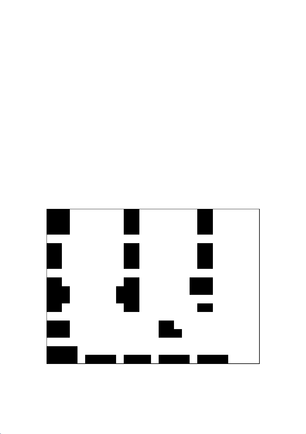
screen 2 ( 5-4 )
V12: 0.0 V V1: 0.0 V A1: 0.00 A
V23: 0.0 V V2: 0.0 V A2: 0.00 A
V31: 0.0 V V3: 0.0 V A3: 0.00 A
P1: - 0.000 KW S1: 0.000 KVA Q1: - 0.000 KVAR
P2: - 0.000 KW S2: 0.000 KVA Q2: - 0.000 KVAR
P3: - 0.000 KW S3: 0.000 KVA Q3: - 0.000 KVAR
PΣ - 0.000 KW SΣ : 0.000 KVA QΣ : - 0.000 KVAR
PF1: -0.00 PF2: -0.00 PF3: -0.00
PFΣ : 0.00 PFH: 0.00
Φ 1: -0.0° Φ 2: -0.0° Φ3: -0.0°
WH: 0.000 KWH SH: 0.000 KVAH
QH: 0.000 KVARH FREQ: 0.0 Hz
CP1201
20A 3Φ 4W SEC: 2 CT: 1 PT: 1
51
Page 56

5-5 The CT and PT measurement
A : Diagram
screen 1 ( 5-5 )
B : Operation Instructions
B-1 : Power on the instrument by pressing POWER KEY,
and then press 1Φ 3Φ KEY to select the 3Φ 4W system,
the selected name of system will be appeared on bottom
left display of screen 2.
B-2 : Connect the line voltage L1, L2, L3 and Vn to V1,
V2, V3 and N terminals of the instrument.
B-3 : Place the conductor of CP-1201(A1), CP-1201(A2),
CP-1201(A3) hook to A1, A2 , A3 as screen 1.
B-4: Connect the outputs of clamp meter CP-1201(A1),
CP-1201(A2), CP-1201(A3) to A1, A2, A3 terminals
of the instrument.
B-5: The related measuring factors will be appeared on
display, about the instruction of factor please refer
appendix 1 ( 5-16, page 68 ).
52
Page 57
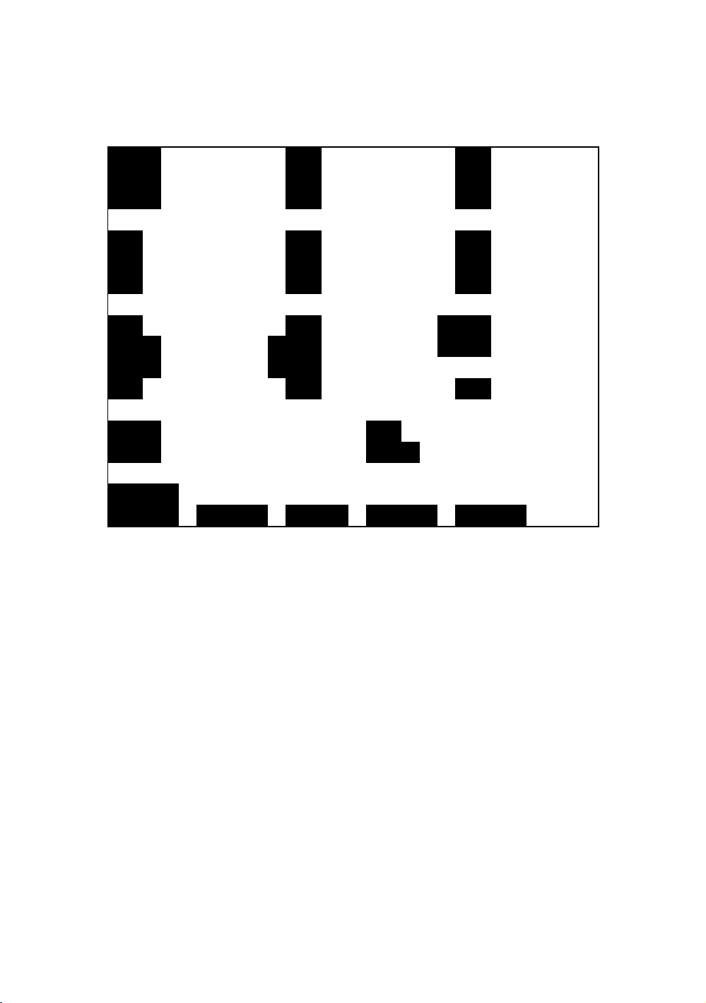
screen 2 ( 5-5 )
V12: 0.0 V V1: 0.0 V A1: 0.00 A
V23: 0.0 V V2: 0.0 V A2: 0.00 A
V31: 0.0 V V3: 0.0 V A3: 0.00 A
P1: - 0.000 KW S1: 0.000 KVA Q1: - 0.000 KVAR
P2: - 0.000 KW S2: 0.000 KVA Q2: - 0.000 KVAR
P3: - 0.000 KW S3: 0.000 KVA Q3: - 0.000 KVAR
PΣ - 0.000 KW SΣ : 0.000 KVA QΣ : - 0.000 KVAR
PF1: -0.00 PF2: -0.00 PF3: -0.00
PFΣ : 0.00 PFH: 0.00
Φ 1: -0.0° Φ 2: -0.0° Φ3: -0.0°
WH: 0.000 KWH SH: 0.000 KVAH
QH: 0.000 KVARH FREQ: 0.0 Hz
CP1201
20A 3Φ 4W SEC: 2 CT: 1 PT: 1
5-6 ZERO adjustment for Watt Hour
If reset the " Exit key button " ( 3-8, Fig. 1 ) continuously
and > 6 seconds, the measurement value of " WH ", " SH ",
" QH " will reset to Zero value.
53
Page 58
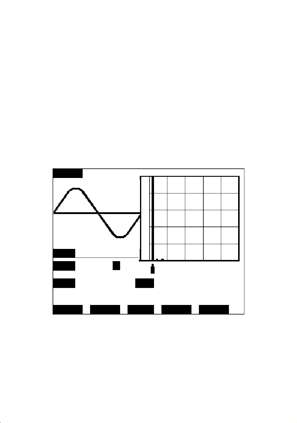
5-7 Harmonic Function Measurement
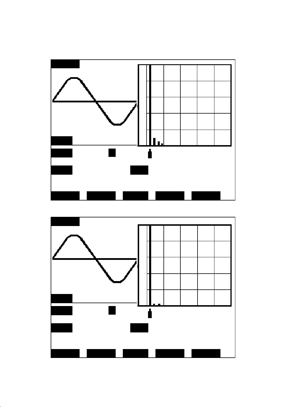
1)Press " Harmonic Key " ( 3-25, Fig. 1 ) will enter
the Screen 1.
2)Press " V/A 1. 2. 3 Key " ( 3-27, Fig. 1 ) will enter
the Screen 2.
3)If the wave show the distortion, Press " V/A range Key "
( 3-28, Fig. 1 ), switch to VH or AH to let the wave
form not existing distortion as Screen 3, Screen 4.
4)Press " Left Key " ( 3-24, Fig. 1) or " Right Key " (
3-26, Fig. 1) will show the voltage or current Nth
harmonic value
Screen 1 ( 5-7 )
Pk-Pk : 623.1 V
CFV : 1.414
V1 : 220.3 V L
THD: 1.5% HD1: 100.0% 220.3V 60Hz
2.8°
CP1201 FREQ: 59.9Hz
200A 3Φ 4W SEC: 2 CT: 1 PT: 2
54
Page 59
Screen 2 ( 5-7 )
Pk-Pk : 216.0 A
CFA : 1.414
A1 : 70.47 A L
THD: 5.5% HD1: 100.0% 70.47A 60Hz
1.8°
CP1201 FREQ: 59.9Hz
200A 3Φ 4W SEC: 2 CT: 1 PT: 2
Screen 3 ( 5-7 )
Pk-Pk : 623.1 V
CFV : 1.414
V1 : 220.3 V H
THD: 1.7% HD1: 100.0% 220.5V 60Hz
1.9°
CP1201 FREQ: 59.9Hz
200A 3Φ 4W SEC: 2 CT: 1 PT: 2
55
Page 60

Screen 4 ( 5-7 )
Pk-Pk : 201.6 A
CFA : 1.414
A1 : 73.97 A H
THD: 5.0% HD1: 99.5% 73.63A 60Hz
3.0°
CP1201 FREQ: 59.9Hz
200A 3Φ 4W SEC: 2 CT: 1 PT: 2
5-8 Graphic Phasor Diagram
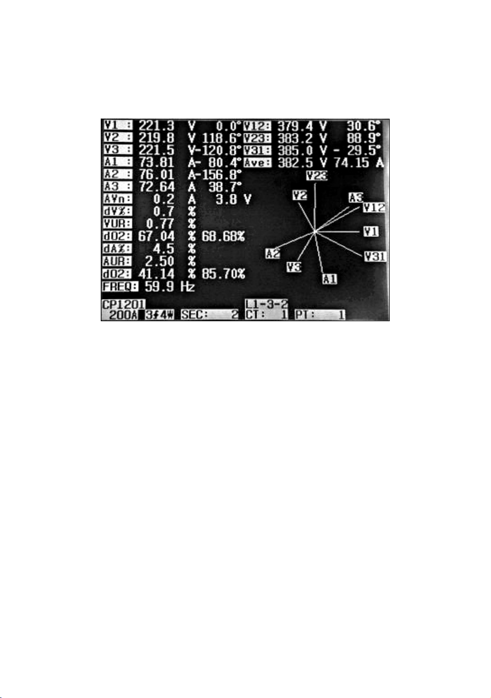
1)Press " Phase Diagram Key " ( 3-30, Fig. 1 ) will display
the phasor diagram as the Screen 1.
2)Description of phasor diagram :
a.
V1, V2, V3 :
Phase voltages in phasor format with respect to V1.
A1, A2, A3 :
Line currents in phasor format with respect to A1.
b. AVE :
Average of the line voltages V12, V23 and V31
an the line current A1, A2 and A3.
c. AVn :
Calculated voltage and current of neutral with respect
to ground.
d. dV% :
Historical maximum % value of
( Max. ( V1, V2, V3 ) - Min. ( V1, V2, V3 ))/
Min. ( V1, V2, V3 ) * 100%
e. VUR :
Voltage unbalance ratio.
56
Page 61
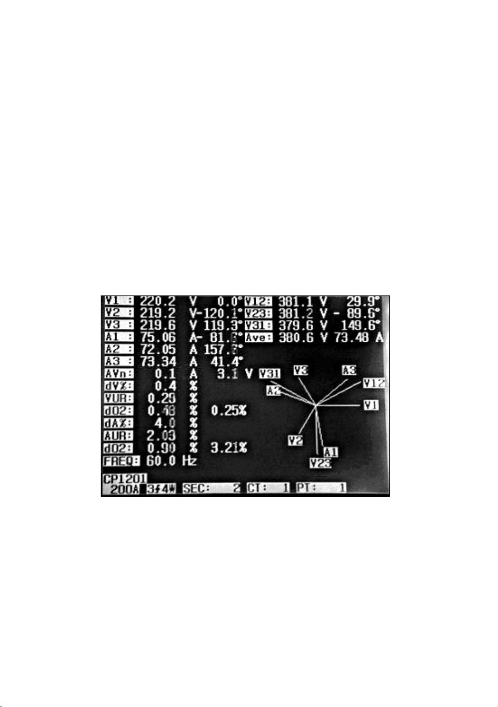
f. do2 ( do, d2 ) :
g
* do - The first number is Zero Sequence Unbalance
Ratio in % ( d0 ) of voltage or current.
* d2 - The second number is the Negative Sequence
Unbalance Ratio in % ( d2 ) of voltage or current.
. dA% :
Historical maximum % value of
( Max. ( A1, A2, A3 ) - Min. ( A1, A2, A3 ))/
Min. ( A1, A2, A3 ) * 100%
h. AUR :
Current unbalance ratio.
Screen 1 ( 5-8 )
57
Page 62
Screen 2 ( 5-8 )
5-9 Voltage/Current Waveform
1)Press " Waveform Key " ( 3-31, Fig. 1 ) will enter to
Voltage Waveform screen as Screen 1, then Press
" 1Φ /3Φ Key " ( 3-2, Fig. 1 ) once in sequence
will switch the Voltage waveform from V1 to V2, V3.
2)Press " Waveform Key " ( 3-31, Fig. 1 ) once again will
enter to Current Waveform screen as Screen 2, then
" 1Φ /3Φ Key " ( 3-2, Fig. 1 ) once in sequence
will switch the Current waveform from A1 to A2, A3.
3)Press " Waveform Key " ( 3-31, Fig. 1 ) once again will
enter to Voltage/Current Waveform screen as Screen 3,
then press " 1Φ /3Φ Key " ( 3-2, Fig. 1 ) once in
sequence will switch the Voltage/Current waveform
from V1/A1 to V2/A2, V3/A3.
58
Page 63
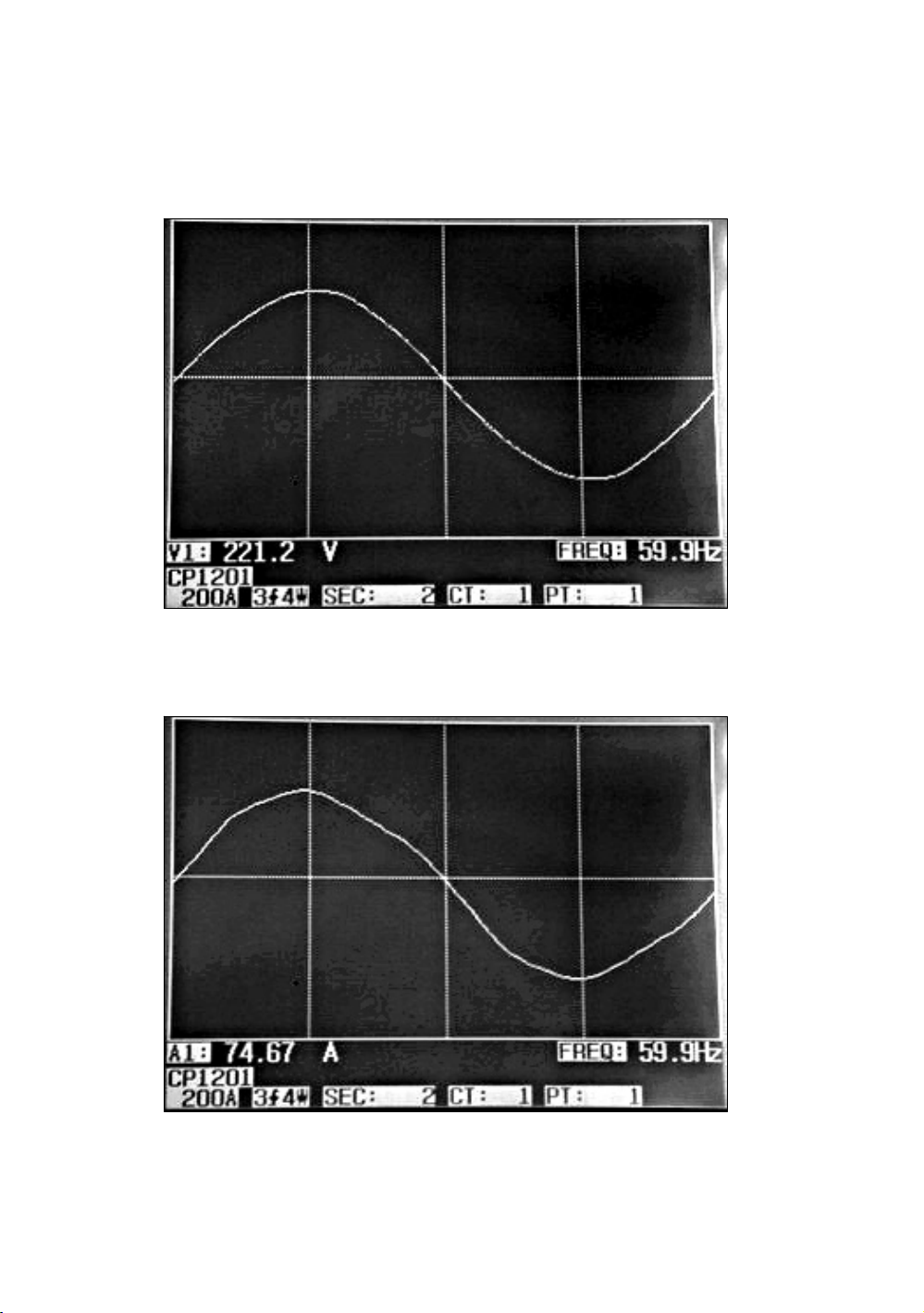
Screen 1 ( 5-9 )
Screen 2 ( 5-9 )
59
Page 64

Screen 3 ( 5-9 )
5-10 Transient Capture ( Dips, Swells, Outage )
1)If intend to make the Transient Capture measurement it
should set the transient voltage level ( high level, low
level ) at first , the setting procedures, please refere to
chapter 4-5-9 and chapter 4-5-10.
2)Press " Transient Key " ( 3-32, Fig. 1 ) will enter to
Transient Capture screen, insert the SD memory card
then press the " REC Button " ( 3-9, Fig. 1 ) will make
the measuremnt, refer as the Screen 1
3)Definition :
a. SWELL :
Vrms > ( Vref + ( Vref * SDVP% ) )
b. DIP
Vrms < ( Vref - ( Vref * SDVP% ) )
c. OUTAGE
Vrms < 30 V to 40 V.
60
Page 65
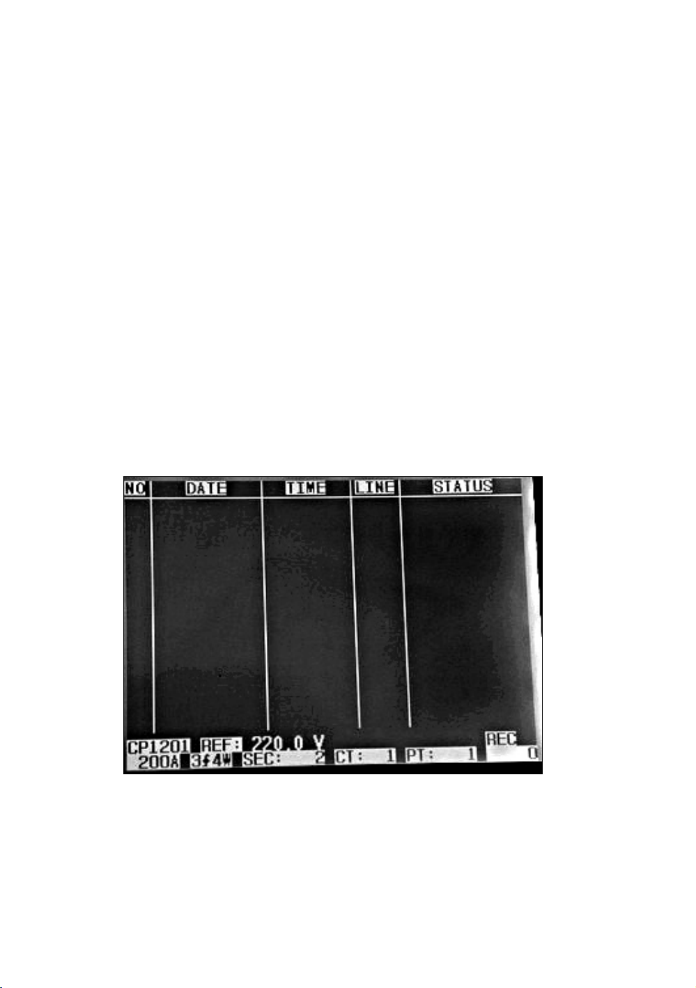
d. Line item :
* V is the code show the all phase V1, V2, V3 ever
happen the transient event.
* V1, V2, V3 is the code that show each phase V1,
V2, V3 ever happen the transient event.
* Refer to Screen 2.
4)Press the " REC Button " will exit the Transient Capture
function as Screen 3.
5)One screen can show 13 transient events.
One file can record 99 transient events.
When the transient even more than 13 no, then
press the " Button " , " Button " can show more▼▲
transient events. If the transient events less than 13 no.,
" Button " , " Button " are disable.▼▲
Screen 1 ( 5-10 )
Remark :
When press " 1Φ 3Φ Button " ( 3-2, Fig. 1 ) once in insequence,
it can switch to the the transient measurement of different
Wire connections such as 1P2W, 1P3W, 3P3W, 3P4W.
61
Page 66
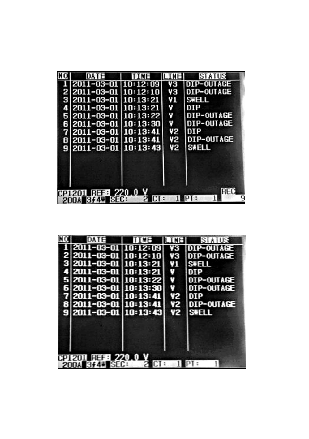
Screen 2 ( 5-10 )
Screen 3 ( 5-10 )
62
Page 67
5-11 Data Logger Function
A : Press REC KEY once to start the data record function.
A-1 : If the bottom right shows as " Change Card ", it
indicates the memory space is already full either or the
SD CARD exist some wrong.
A-2 : If the SD CARD is normal, the data logger function
will start to be executed.
V12: 0.0 V V1: 0.0 V A1: 0.00 A
V23: 0.0 V V2: 0.0 V A2: 0.00 A
V31: 0.0 V V3: 0.0 V A3: 0.00 A
P1: - 0.000 KW S1: 0.000 KVA Q1: - 0.000 KVAR
P2: - 0.000 KW S2: 0.000 KVA Q2: - 0.000 KVAR
P3: - 0.000 KW S3: 0.000 KVA Q3: - 0.000 KVAR
PΣ - 0.000 KW SΣ : 0.000 KVA QΣ : - 0.000 KVAR
PF1: -0.00 PF2: -0.00 PF3: -0.00
PFΣ : 0.00 PFH: 0.00
Φ 1: -0.0° Φ 2: -0.0° Φ3: -0.0°
WH: 0.000 KWH SH: 0.000 KVAH
QH: 0.000 KVARH FREQ: 0.0 Hz
CP1201 Change
20A 3Φ 4W SEC: 2 CT: 1 PT: 1 Card
B : The bottom right display will show the recorded data
points.
B-1 : Each file can record up to 30,000 data points as
screen 1 when the record points exceed 30,000 points,
system will create a new file automatically. (For example,
WTA01001.XLS will be replaced by WTA01002.XLS)
B-2 : While pressing REC KEY twice, the data logger
function will stop to execute, the record points will
disappear on bottom right display as screen 2.
63
Page 68
screen 1 ( 5-11 B )
V12: 0.0 V V1: 0.0 V A1: 0.00 A
V23: 0.0 V V2: 0.0 V A2: 0.00 A
V31: 0.0 V V3: 0.0 V A3: 0.00 A
P1: - 0.000 KW S1: 0.000 KVA Q1: - 0.000 KVAR
P2: - 0.000 KW S2: 0.000 KVA Q2: - 0.000 KVAR
P3: - 0.000 KW S3: 0.000 KVA Q3: - 0.000 KVAR
PΣ - 0.000 KW SΣ : 0.000 KVA QΣ : - 0.000 KVAR
PF1: -0.00 PF2: -0.00 PF3: -0.00
PFΣ : 0.00 PFH: 0.00
Φ 1: -0.0° Φ 2: -0.0° Φ3: -0.0°
WH: 0.000 KWH SH: 0.000 KVAH
QH: 0.000 KVARH FREQ: 0.0 Hz
CP1201 REC
20A 3Φ 4W SEC: 2 CT: 1 PT: 1 9
screen 2 ( 5-11 B )
V12: 0.0 V V1: 0.0 V A1: 0.00 A
V23: 0.0 V V2: 0.0 V A2: 0.00 A
V31: 0.0 V V3: 0.0 V A3: 0.00 A
P1: - 0.000 KW S1: 0.000 KVA Q1: - 0.000 KVAR
P2: - 0.000 KW S2: 0.000 KVA Q2: - 0.000 KVAR
P3: - 0.000 KW S3: 0.000 KVA Q3: - 0.000 KVAR
PΣ - 0.000 KW SΣ : 0.000 KVA QΣ : - 0.000 KVAR
PF1: -0.00 PF2: -0.00 PF3: -0.00
PFΣ : 0.00 PFH: 0.00
Φ 1: -0.0° Φ 2: -0.0° Φ3: -0.0°
WH: 0.000 KWH SH: 0.000 KVAH
QH: 0.000 KVARH FREQ: 0.0 Hz
CP1201
20A 3Φ 4W SEC: 2 CT: 1 PT: 1
64
Page 69
5-12 Data HOLD Function
V
V
V
V
V
V
V
V
V
V
V
V
Q
Q
Q
Q
Q
V
V
V
V
V
V
V
V
V
V
V
V
Q
Q
Q
Q
Q
A: During the measurement, press HOLD KEY once, the
bottom right display will show “ HOLD symbol as screen 1.
B: Press the HOLD KEY twice will disable the Data HOLD
function and the “ HOLD” symbol will disappear in the
meantime
screen 1 ( 5-12 )
12: 0.0
23: 0.0
31: 0.0
1: 0.0
2: 0.0
3: 0.0
A1: 0.00 A
A2: 0.00 A
A3: 0.00 A
P1: - 0.000 KW S1: 0.000 KVA
P2: - 0.000 KW S2: 0.000 KVA
P3: - 0.000 KW S3: 0.000 KVA
PΣ - 0.000 KW SΣ : 0.000 KVA
PF1: -0.00 PF2: -0.00 PF3: -0.00
PFΣ : 0.00 PFH: 0.00
Φ 1: -0.0° Φ 2: -0.0° Φ3: -0.0°
WH: 0.000 KWH SH: 0.000 KVAH
H: 0.000 KVARH FREQ: 0.0 Hz
CP1201
20A 3Φ 4W SEC: 2 CT: 1 PT: 1 HOLD
1: - 0.000 KVAR
2: - 0.000 KVAR
3: - 0.000 KVAR
Σ : - 0.000 KVAR
screen 2 ( 5-12 )
12: 0.0
23: 0.0
31: 0.0
P1: - 0.000 KW S1: 0.000 KVA
P2: - 0.000 KW S2: 0.000 KVA
P3: - 0.000 KW S3: 0.000 KVA
PΣ - 0.000 KW SΣ : 0.000 KVA
PF1: -0.00 PF2: -0.00 PF3: -0.00
PFΣ : 0.00 PFH: 0.00
Φ 1: -0.0° Φ 2: -0.0° Φ3: -0.0°
1: 0.0
2: 0.0
3: 0.0
A1: 0.00 A
A2: 0.00 A
A3: 0.00 A
1: - 0.000 KVAR
2: - 0.000 KVAR
3: - 0.000 KVAR
Σ : - 0.000 KVAR
WH: 0.000 KWH SH: 0.000 KVAH
H: 0.000 KVARH FREQ: 0.0 Hz
CP1201
20A 3Φ 4W SEC: 2 CT: 1 PT: 1
65
Page 70
5-13 BACKLIGHT KEY
Control the backlight function of LCD to ON/OFF
5-14 A Range ( Current Range ) KEY function
a) The A Range ( Current Range ) function key is used to
change the current range quickly.
b)Press A RANGE KEY once will entry to screen
as following " screen 1 ( 5-14 ) " , it is the same
screen as " screen 2 ( 4-5-13 ) , page 37 ".
c) The detail Current range Setting procedures, please
reafer to section " 4-5-13 A range Setting ( Current
range Setting ), page 37 "
Remark :
The function of the " A Range ( Current Range )
key " is available for the Clamp Type, A Range,
V Range setting only.
screen 1 ( 5-14 ) same as screen 2 ( 4-5-13 )
Folder Name: WTA01 SETUP
File Name: 3P401001.XLS
REC Date: 2008-11-28 00:03:17
Sampling Time: 2 Trans Ref : 220.0 V
Delete File: 0 % SDVP 0
SD Format: 0 % Decimal: Basic
Use Size: 388 KB Clamp Type: CP1201
Free Size: 1946 MB ARange: 200A
Total Size: 1946 MB V Range: 200mV
RS232 Out Sel:
PT: 1 : 1 V1 I1 P1
CT: 1 : 1 S1 Q1 PF1
Beep: ON Φ1 FREQ
Year Month Date Hour Minute Second
2010 11 13 14 37 25
66
Page 71
5-15 The LOWBAT screen: as show on lower right
V
V
V
V
V
V
V
V
V
V
V
V
Q
Q
Q
Q
Q
display of the following screen.
12: 0.0
23: 0.0
31: 0.0
P1: - 0.000 KW S1: 0.000 KVA
P2: - 0.000 KW S2: 0.000 KVA
P3: - 0.000 KW S3: 0.000 KVA
PΣ - 0.000 KW SΣ : 0.000 KVA
PF1: -0.00 PF2: -0.00 PF3: -0.00
PFΣ : 0.00 PFH: 0.00
Φ 1: -0.0° Φ 2: -0.0° Φ3: -0.0°
WH: 0.000 KWH SH: 0.000 KVAH
H: 0.000 KVARH FREQ: 0.0 Hz
CP1201 LOWBAT
20A 3Φ 4W SEC: 2 CT: 1 PT: 1
1: 0.0
2: 0.0
3: 0.0
A1: 0.00 A
A2: 0.00 A
A3: 0.00 A
1: - 0.000 KVAR
2: - 0.000 KVAR
3: - 0.000 KVAR
Σ : - 0.000 KVAR
67
Page 72

5-16 Appendix 1
* V12, V23, V31 : Line Voltage
* V1, V2, V3 : Phase Voltage
* A1, A2, A3 : Line Current
* P1, P2, P3 : True Power of each phase. (W)
* S1, S2, S3 : Apparent Power of each phase. (VA)
* Q1, Q2, Q3 : Reactive Power of each phase (VAR)
* PΣ : Total True Power (W)
* SΣ : Total Apparent Power (VA)
* QΣ : Total Reactive Power (VAR)
* PF1, PF2, PF3 : Power Factor of each phase
* PFΣ : Total Power Factor
* PFH : Long Term Average Power Factor ( WH/SH )
* Φ 1, Φ 2, Φ 3 : Phase Angle of each phase
* WH : Watt Hour
* SH : Apparent Power Hour
* QH : Reactive Power Hour
* 1Φ 2W : One phase by two wires
* 1Φ 3W : One phase by three wires
* 3Φ 3W : Three phases by three wires
* 3Φ 4W : Three phases by four wires
* SEC : The sampling time of data logger
* CT : Current transformer
* PT : Potential transformer
68
Page 73

6. MAINTENANCE
Caution :
Remove test leads before
opening the battery cover
or housing case !
6-1 Cleaning
Caution :
Cleaning - Only use
the dry cloth to clean
the plastic case !
6-2 Replacement of batteries
1)When Display show the " LOWBAT " indicator ( ref. 5-15
page 67 ), it should change the batteries.
2)open the " Battery Cover " ( 3-19, Fig. 1 ) away from the
instrument and remove the battery.
3)Replace with batteries ( DC 1.5V, AA/UM-3 battery
X 8 PCs ) and reinstate the cover.
* When install the batteries, should make
attention the battery polarity.
4)Make sure the battery cover is secured after changing
the batteries.
69
Page 74
7. RS232 PC SERIAL OUTPUT
.
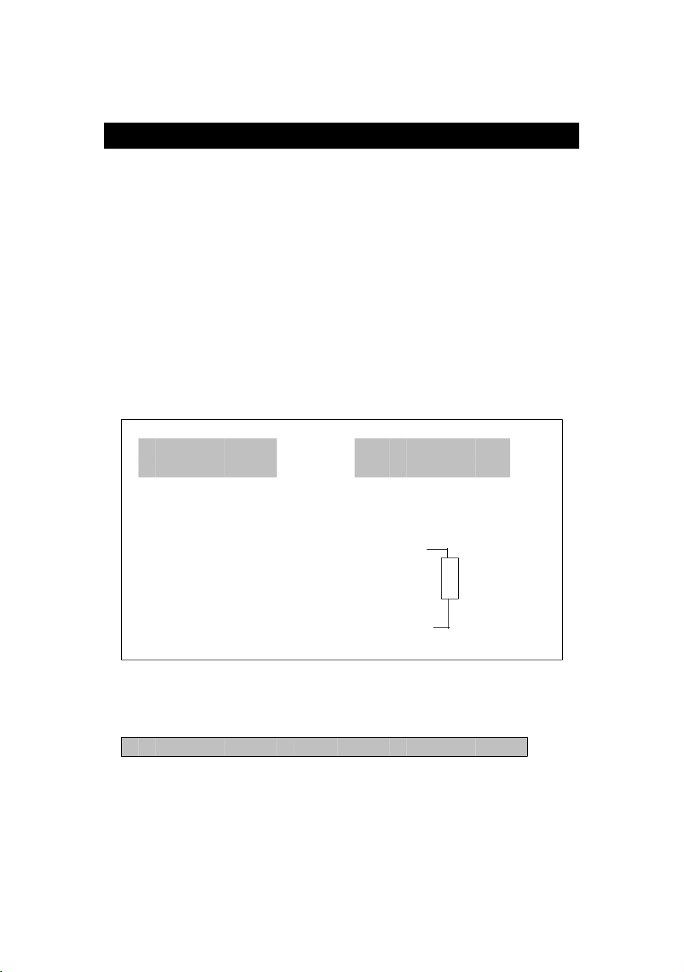
The instrument is provided an 3.5 mm dia. phone socket
( 3-16, Fig. 1 ) for RS232 computer interface socket.
The connector output is a 16 digits data stream which
can be utilized to the user's specific application.
A RS232 lead with the following connection will
be required to link the instrument with the PC
serial input.
Meter PC
(3.5 mm jack plug) (9W 'D" Connector)
Center Pin...............................Pin 4
Ground/shield...........................
Pin 2
2.2 K
resister
Pin 5
The 16 digits data stream will be displayed in the
following format :
D15 D14 D13 D12 D11 D10 D9 D8 D7 D6 D5 D4 D3 D2 D1 D0
70
Page 75
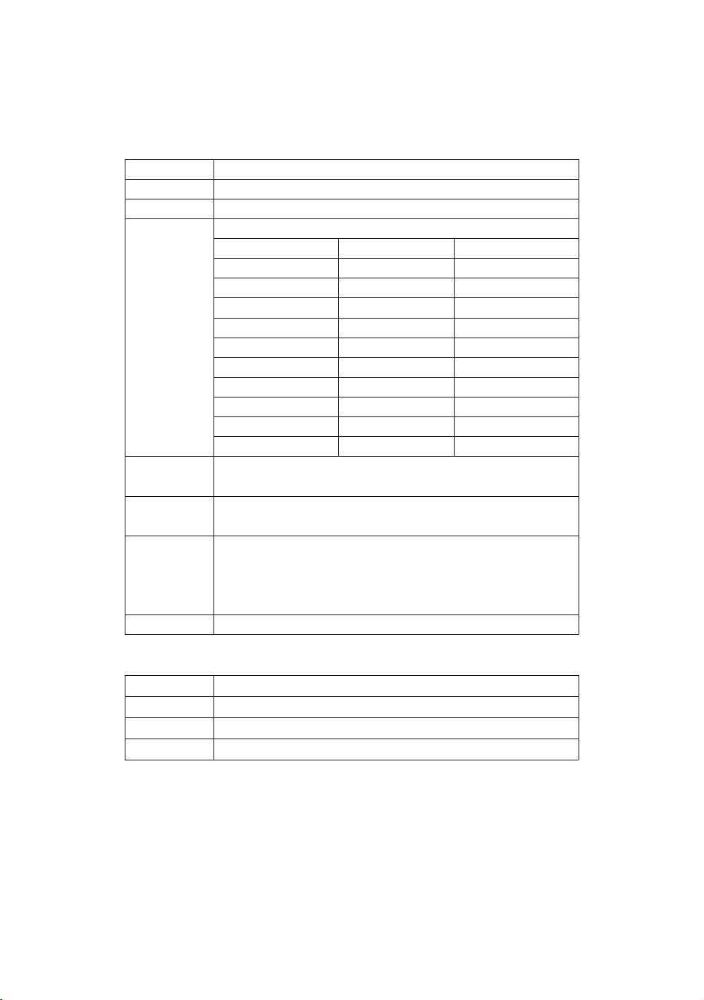
Each digit indicate the following status :
D15 Start Word
D14 4
D13 1
D12 & D11 Annunciator for Display
03=% B9 = MACA D0 = MW/Hr
31=HZ C0 = MW D1 = GW/Hr
32=DEGREE C1 = GW D2 = TW/Hr
48=K WATT C2 = TW D3 = KVA/Hr
50=ACV C3 = MVA D4 = MVA/Hr
52=ACA C4 = GVA D5 = GVA/Hr
64=KVA C5 = TVA D6 = TVA/Hr
65=KW/HR C6 = KVAR D7 = KVAR/Hr
B6 = KACV C7 = MVAR D8 = MVAR/Hr
B7 = MACV C8 = GVAR D9 = GVAR/Hr
B8 = KACA C9 = TVAR E0 = TVAR/Hr
D10 Polarity
0 = Positive 1 = Negative
D9 Decimal Point(DP), position from right to the left
0 = No DP, 1= 1 DP, 2 = 2 DP, 3 = 3 DP
D8 to D1 Display reading, D1 = LSD, D8 = MSD
For example :
If the display reading is 1234, then D8 to D1 is :
00001234
D0 End Word
RS232 setting
Baud rate 9600
Parity No parity
Data bit no. 8 Data bits
Stop bit 1 Stop bit
71
Page 76
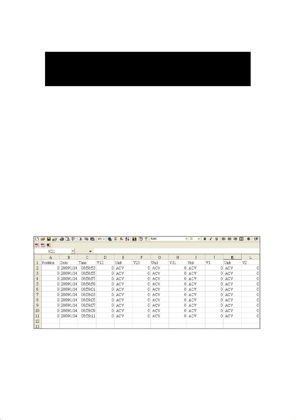
8. Download the saving data from the
SD card to the computer ( EXCEL
software )
1)After execute the Data Logger function, take away the
SD card out from the " SD card socket " ( 3-15, Fig. 1 ).
2)Plug in the SD card into the Computer's SD card slot
( if your computer build in this installation ) or
insert the SD card into the " SD card adapter ". then
connect the " SD card adapter " into the computer.
3)Power ON the computer and run the " EXCEL software ".
Down load the saving data file ( for example the file
name : 3P401001.XLS, 1P201001.XLS, 1P301001.XLS,
3P301001.XLS........) from the SD card to the
computer. The saving data will present into the EXCEL
software screen ( for example as following EXCEL data
screens ) , then user can use those EXCEL data to make
the further Data or Graphic analysis usefully.
EXCEL data screen 1 ( for example )
72
Page 77
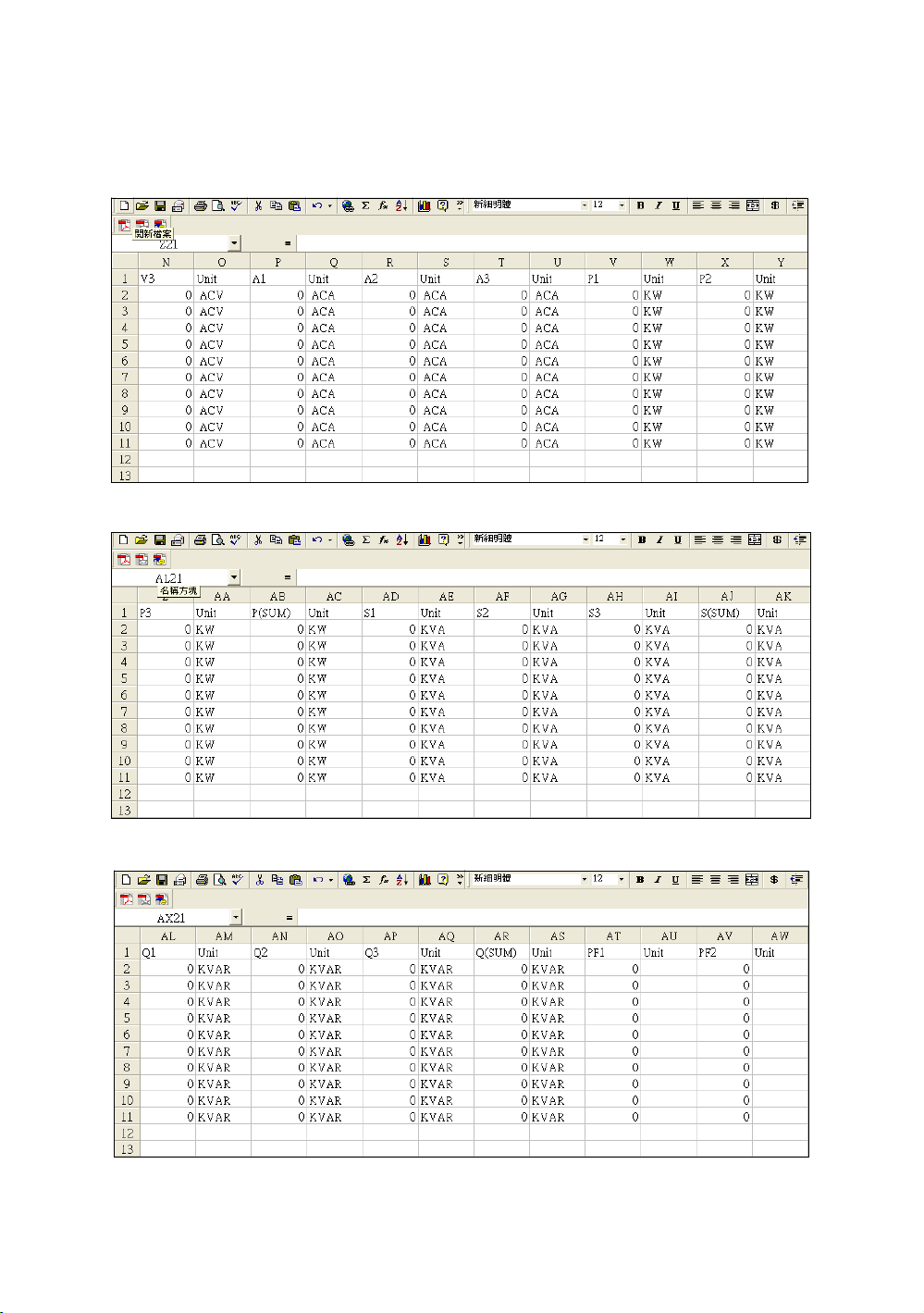
EXCEL data screen 2 ( for example )
EXCEL data screen 3 ( for example )
EXCEL data screen 4 ( for example )
73
Page 78
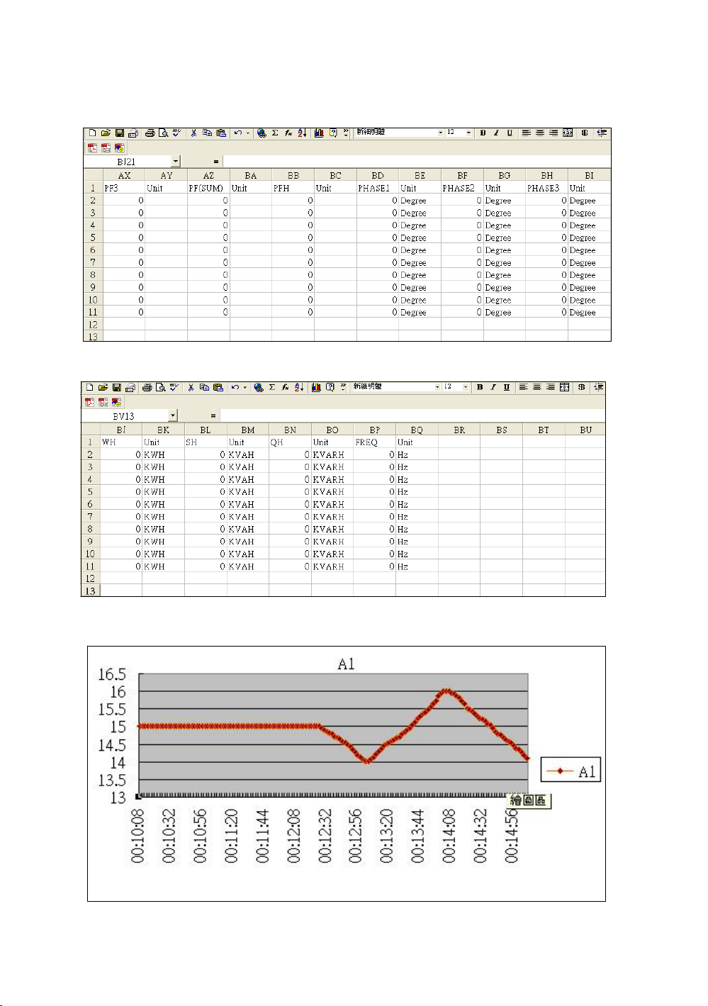
EXCEL data screen 5 ( for example )
(
)
EXCEL data screen 6
for example
EXCEL graphic screen 1 ( for example )
74
Page 79
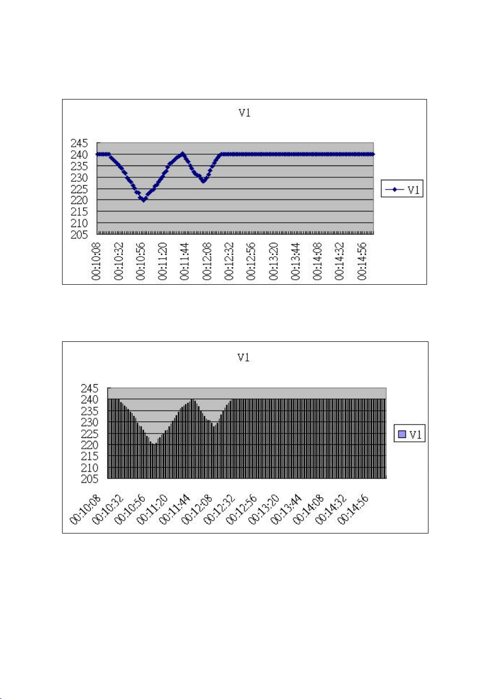
EXCEL graphic screen 2 ( for example )
EXCEL graphic screen 3 ( for example )
75
Page 80
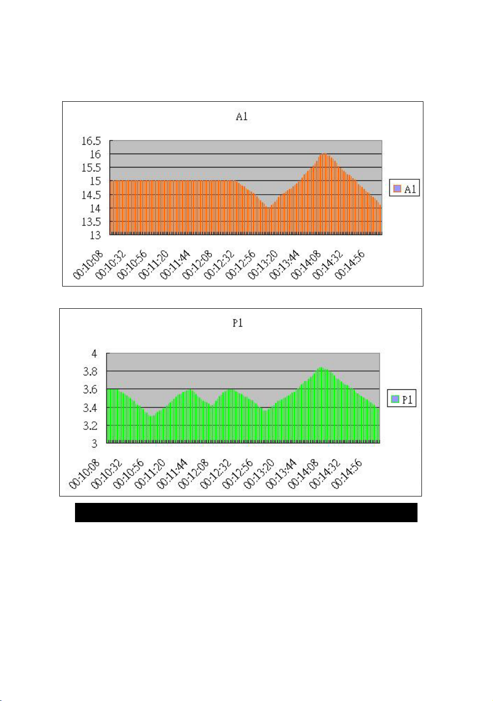
EXCEL graphic screen 4 ( for example )
grap
)
EXCEL
hic screen 5 ( for example
9. PATENT
The meter ( SD card structure ) already
get patent or patent pending in following
countries :
76
Page 81
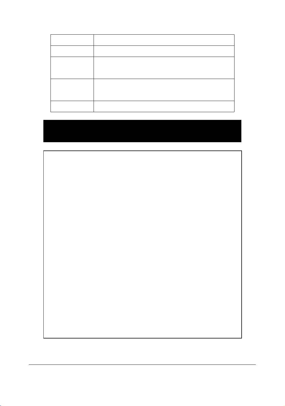
Germany Nr. 20 2008 016 337.4
JAPAN 3151214
TAIWAN M 358970
M 359043
CHINA ZL 2008 2 0189918.5
ZL 2008 2 0189917.0
USA Patent pending
10. THE ADDRESS OF AFTER SERVICE
CENTER
77
1106-DW6095
1012-DW6095
 Loading...