

Page 1

PCE Americas Inc.
711 Commerce Way
Suite 8
Jupiter
FL-33458
USA
From outside US: +1
Tel: (561) 320-9162
Fax: (561) 320-9176
[email protected]
Instruction Manual
HVAC Meter PCE-PXX
PCE Instruments UK Ltd.
Units 12/13
Southpoint Business Park
Ensign way
Hampshire / Southampton
United Kingdom, SO31 4RF
From outside UK: +44
Tel: (0) 2380 98703 0
Fax: (0) 2380 98703 9
www.pce-instruments.com/english
www.pce-instruments.com
Page 2

INTRODUCTION ..................................................................................................................... 3
CONVERSION ........................................................................................................................ 3
CONROLS AND INDICATORS ............................................................................................... 3
AUTO POWER OFF (SLEEP FUNCTION) .......................................................................... 4
MODE OPTIONS ................................................................................................................. 4
MAINTENANCE ...................................................................................................................... 5
CALIBRATION MODE ......................................................................................................... 6
CALIBRATION POINT REFERENCE ................................................................................. 7
MANUAL ZERO SETTING .................................................................................................. 7
TROUBLESHOOTING ......................................................................................................... 7
REPLACING THE BATTERY .............................................................................................. 7
OPERATING CONDITIONS ................................................................................................ 7
SPECIFICATION ................................................................................................................. 8
RS232 OUTPUT .................................................................................................................. 8
WARRANTY ............................................................................................................................ 8
RETURN AUTHORIZATION ............................................................................................... 8
2
Page 3
Congratulations on your purchase of the Manometer! This instrument is portables battery operated pressure
measuring device.
The Manometer is ideal for HVAC/R technicians measuring pressure level, Medical equipment computer
peripherals, pneumatic Controls.
INTRODUCTION
• The meter will display all LCD segments when it is first turned on for approx. 3 seconds. Though you
might have seen DATALOGGER, Y/M/D, REL, AVG ... these are not available for the meter. The meter
with data logger features named 8205D/821 5D/8280D/821 OOD. Please contact the store or the place
you purchased.
• The LCD is divided into two distinct sections: One large (Primary) top screen and one smaller rightbottom bottom screens (relative Clock), The 2 display areas keep you constantly updated with the)
pressure measurements.
• The Meter measures Gauge pressure-a measure of pressure in psi that is referenced to ambient
pressure and Differential pressure - a measure of the difference two pressures.
• 11 pressure units are selectable for Imperial and Metric in the different area: bar, mmHg, ozin², kgcm²,
psi, inH2, kPa, ftH2O|, inHg, cmH2O, mbar.
• Please check the tubing is not leakage or damaged before using
CONVERSION
Manometer PSI Inch of
mbar kg/cm³
H2O
PCE-P05 5 138 345 0,35
PCE-P15 15 415 1034 1,05
PCE-P30 30 830 2068 2,10
PCE-P50 100 2768 6895 7,03
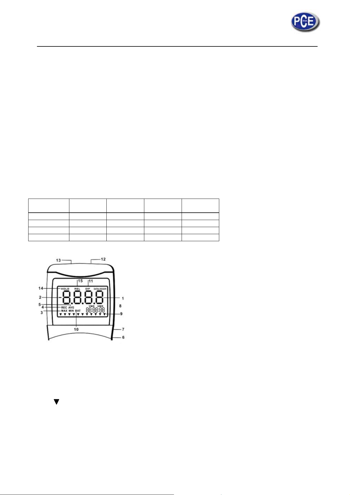
CONROLS AND INDICATORS
1. Primary Data Screen displays pressure value.
2. “-“: Minus pressure display.
3. MAX MIN: pressure recorded.
4. REC: starts recording mode and displays max./min. pressure recorded,
5. AVG: Average records (N/A).
6. DC: power in Jack.
7. RS232: output port.
8. H/M/S 88:88:88: displays data for Hour / Minute / Second.
9. : Pressure unit indication.
10. BAT: Battery low indicator.
11. DIF: Differential pressure mode.
12. “+”: Positive pressure home plug.
13. “-“: Negative pressure hose plug.
14. HOLD: Freezes pressure reading.
15. REL: Establish a relative zero for the primary screen information. (N/A)
3
Page 4
e
o
W
m
n
n
A
a
r
n
n
a
s
s
B
s
u
s
o
L
e
b
o
s
o
y
y
o
r
e
c
g
h
t
b
e
s
s
e
l
d
t
m
u
r
o
t
.
e
o
o
s
l
e
g
t
e
u
b
M
o
o
l
a
m
k
F
u
s
e
b
a
a
T
t
U
e
Note: Ther
sure which
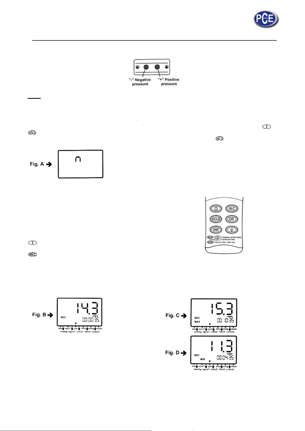
AUTO PO
This instru
For recordi
simulta
n “n” will
disable stee
MODE OPT
Delete and
The display
For your co
The followi
button indic
Turn
Pres
REC
and
Pres
press
Pres
are two c
ne you wan
ER OFF (S
ent will shut
g or operati
eously befo
ppear in th
p mode will
IONS
eplace with
will default t
venience th
g table list
ted.
instrument
momentaril
is displayed
acklight.
momentaril
re; the rec
and hold fo
nnecting m
t before pur
EEP FUNC
off automati
ng over lon
re power on
middle of t
e invalid af
program ca
the mode l
e setting us
the mode
n (Default
and relativ
in the midd
again and
rd mode is
3 seconds
tal lug 5m
hasing the
TION)
cally in app
er periods
.
e screen a
er paper off
le user sele
ast used.
d during th
of operati
etting) and
clock start
e deft of (Fi
the unit cyc
isplayed on
o turn off th
, plastic lu
nit.
ox. 20 minu
f time, you
which ting
ctable start-
last operati
n that can
ff.
in the lowe
g. B) other
es through
the LCD.
normal m
9.25mm f
es for every
can disable
you can re
p mode.
on.
be invoked
r right scree
utton functi
AX (Fig. C
de.
r different
power on.
the sleep
ease the
by
n.
ons are loc
) and man (
pplication p
ode by pre
button. (S
ed out exc
ig. D) and
rpose . M
sing
ee Fig. A)
pressing
pt Power,
ack to curr
ke
nd
he
he
nit
nt
Page 5
s
s
a
P
s
s
g
s
p
N
o
e
f
b
c
p
a
r
a
a
m
s
o
m
r
n
c
m
s
w
m
n
a
e
n
b
o
m
n
z
c
a
e
o
s
h
c
p
c
t
m
g
o
w
f
m
s
s
F
C
w
n
t
o
a
a
o
n
t
o
m
e
e
y
e
b
h
y
h
o
d
p
m
G
m
t
o
r
c
e
s
r
c
2
a
n
e
g
t
s
t
2
s
r
u
v
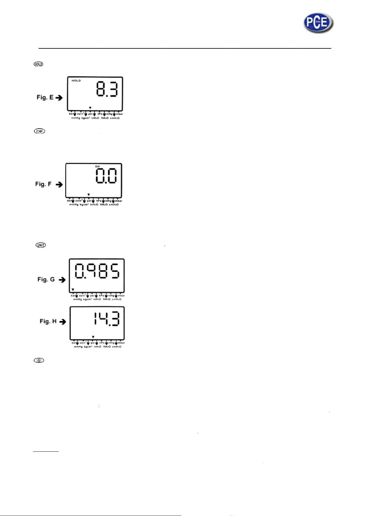
Pre
s momenta
ily to freeze
the pressur
reading. (
ig. E)
Pre
(Rel
will be indic
(see Fig. F).
Differential
to measure
second sen
Pre
inH
s moment
ative zero c
ted. Press
ressure: A
gauge pre
or port to y
s momenta
, cmH2O,
rily, DIF ap
uses the v
omentarily
measure of
sure by 1
ur system.
rily and the
bar, which i
pears on t
lue of the di
again and t
the differen
aving one
unit will cy
dicated on
p of the L
play to sho
e unit retur
e between
rocess con
le through
he bottom
D and tile
as ''0,0'') -
s to the nor
wo pressur
nection op
bar, mmHg
f the displa
display indi
nly the am
al mode of
s, i.e. use
n to atmos
, ozin², kgc
(See Fig.
cates the r
unt of pres
pressure
ifferential p
here and
², psi, inH
& H).
lative zero
ure chan
differen
essure sen
onnecting
, kPa, ftH
re
e
ial
or
he
O,
Pre
Or
MAINTENA
• The
• Wh
• Re
Cleaning:
Use a dam
as these m
s momenta
ress mome
CE
meter is ca
mmend to
rec
n properly
per
orming at it
cali
ration.
ommend al
cloth and
y mar the fi
ily and the
tarily to dec
librated in h
alibrate the
aintained,
peak; se
ays to get
ild soap to
ish or dam
acklight illu
rease the fi
use before
eter after t
the meter
d it to the
ero before
lean the ca
ge the unit'
inates for
ure when c
shipping. T
ng time usi
ill maintain
actory or a
easuremen
e of the Ma
case with a
pprox. 30 s
libration is
maintain t
g.
an accurac
qualified in
prefer to th
nometer do
n adverse c
conds then
eing perfor
e meter in
specificati
strument ca
e zero settin
kcal use ha
emical rea
turns off
ed.
he good co
n to ensur
libration fac
g procedure
sh detergen
tion.
utomatically
dition for u
your mete
ility for ann
in page 10.
ts or abrasi
.
e,
is
al
es
Page 6
m
a
t
o
n
s
b
i
b
r
2
o
o
A
s
t
A
b
r
o
e
d
s
n
a
t
e
s
e
c
a
s
v
n
o
e
n
r
t
o
y
u
a
o
n
i
(
a
o
a
d
z
u
a
t
e
r
s
o
n
e
2
r
e
s
n
b
t
'
e
e
p
h
e
o
d
y
u
'
p
c
n
n
r
r
s
o
s
a
r
o
r
m
p
m
s
S
s
p
0
l
u
t
0
t
g
e
f
n
e
-
e
i
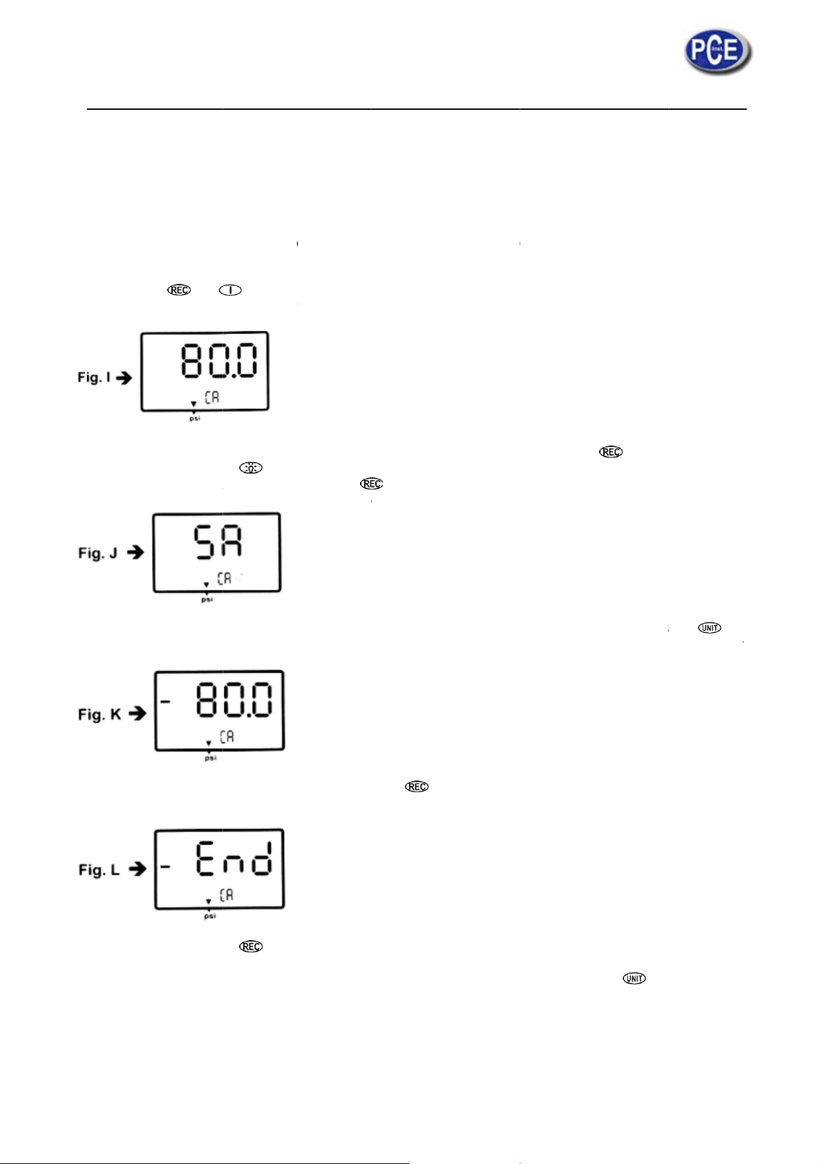
CALIBRATI
Calibration
for annual c
1. Firs
zer
2. Tur
3. Pre
cali
pos
4. The
cali
figu
5. Sav
) in
ON MODE
ode is only
libration,
, please ma
procedure.
the meter
s &
ration mod
tive (+) pres
meter has
ration pres
e by pressi
e the calibr
seconds ,
applicable f
nually set th
ff.
simulta
, make su
sure calibra
efaulted as
ure source
g key t
tion point b
he meter a
r a standar
display to
eously ''CA'
e the press
ion
80 psi calibr
is not 80 psi
set calibra
pressing
to-skip to th
Manomet
ero (no pre
' appears o
re unit to
tion point,
, to increas
ion point as
key , ''SA
negative p
r calibrator
sure applie
the displa
e pointed
he adjustabl
e the figure
required.
' and small '
ressure (-)
r any qualifi
to the con
, (See Fig.
nder the a
e pressure
by pressing
CA” appear
oint for next
ed meter ca
ector), refe
I) the mete
row mark
ange in fro
key , o
on the dis
calibration
libration faci
to the Man
r enters to
is psi st
78.0 to 82.
r decrease
lay (See Fi
ode.
ity
al
he
art
if
he
. J
6. Foll
the
to y
ga
7.
End
If you can't
between 75
If you want
) calibration
bove cali
pressure) o
w the sam
LCD now di
ur pressur
in save the
'' and ''CA''
ave by pre
.0 and 85.0
o skip positi
point.
ration is a
from 0 to -1
procedure
plays '' -80
standard if
alibration p
ppears in a
s key,
, or check
e (+) calibr
example f
00 psi (Neg
s step 4 fo
,0 '' and sm
needed.
int by pres
other 2 sec
.e. no ''SA''
b) if you e
tion when
r model 8
tive pressu
the negativ
all ''CA'' (Se
ing k
nds, the m
appeared,
ter the rig
ntered to th
100, i.e. th
e).
e pressure
e Fig. K ), d
y, ''SA'' and
ter turns ba
lease check
t positive p
Calibratio
e pressure
alibration p
o the neces
''CA'' appe
ck to the no
: (a) The cal
ressure (+)
mode, pres
range is fr
int by pres
ary calibrat
rs in 2 seco
mal mode (
ibration pre
or negative
s to ski
m 0 to +1
ing k
ion figure re
nds and the
ee Fig . L).
sure sourc
pressure (
to negativ
0psi (Posit
y ,
er
''
is
) .
(-
ve
Page 7

CALIBRATION POINT REFERENCE
Model psi-range Calibration point (±) Recommend
PCE-P05 0 ~ ±5 4,000 3,900 ~ 4,100
PCE-P15 0 ~ ±15 12,00 11,70 ~ 12,30
PCE-P30 0 ~ ±30 24,00 23,40 ~ 24,60
PCE-P50 0 ~ ±100 80,00 78,00 ~ 82,00
MANUAL ZERO SETTING
When you set the display to zero (no pressure applied to the connector), press button for 2 seconds, now
the meter display ''0 .0.0.0'' from right to left and then disappear each ''0'' from left back to right, the LCD display
shows a normal mode.
TROUBLESHOOTING
• Power on but no display. Check the batteries are in place and making good contact or correct polarity,
replace a new battery or attach optional AC adaptor for the weak battery caused.
• BAT indication. Replace with a now battery when LCD display BAT at the middle bottom.
• No Display. Make sure battery is not empty, if the display disappears, check sleep mode is active. Refer
to the Disable sleep mode function for a long time using the measurement. Or check the tubing is
connected to the meter tightly.
• Err.1. For the pressure value exceed the maximum range, ''Err. 1'' appears on the display, p1ease
change the sensor, otherwise, the sensor will be hurt for going on the over range measurement.
• Err.2. For the measurement pressure is less than minimum range, ''Err. 2'' will appear recommend to
change the sensor (meter).
• Err.3. For operating the DIF function, the differential pressure value is larger than maximum display
digit, Err.3 appears on the display.
• Err.4. When you set zero, make sure you have disconnected the tubing, no pressure applied to the
connector. Then if you see an Err.4 appears on the display, it means the sensor or meter damaged.
Return the unit to the store you purchased for repaired.
Err.4 will be also appeared while the tube or hose is connecting during setting zero mode.
• E1OL or E2UL. When you see the errors while operating RS232 software, it means pressure source is
less or over than the range of the instrument.
REPLACING THE BATTERY
Replace your 9-volt battery when:
• The BAT icon appears on the right of the screen.
• The meter will not power on.
• Use of the back-light causes the BAT icon to appear.
Even if the battery was recently replaced check its voltage level if you get no response from your instrument.
To replace the battery:
1. Remove the tubing of the instrument.
2. Lay the instrument face-down on a clean, flat surface.
3. Remove the battery by screw driver and observe indicated polarity and close the cover after replacing
with a new battery.
Remove battery from instruments that you do not plan to use for a month or more.
Do not leave battery in instrument.
OPERATING CONDITIONS
• Compensated temperature range: 0 – 50°C
• Operating temperature 0 – 50°C (32 – 122°F)
• Storage temperature range: -20 – 60°C
• Operating Humidity Max. 80% RH
• Power: One 9.0 volt battery
• Exceeding Maximum pressure will cause permanent sensor damage.
Page 8
SPECIFICATION
PCE-P05 PCE-P15 PCE-P30 PCE-P50
Range 0 – 5 psi 0 – 15 psi 0 – 30 psi 0 – 100 psi
Resolution 0,003 psi 0,01 psi 0,02 psi 0,1 psi
Accuracy ±0,3% of full scale at 25°C
Dimension 72 x 182 x 30 mm
Unit Weight Approx. 220 gram (with battery)
Response time 0,5 seconds
Data Format Baud Rate: 2400 bit/sec
Data Bit: 8
Stop Bit: 1
P XXXXX. P -XXXXX (unit)
The meter Pressure measurement instruments are not suitable for the absolute pressure measurement.
The meter instruments are fitted with two 4.8mm lugs. Before you connect the instruments to a pressure
sources, check carefully the security of ail fitting.
RS232 OUTPUT
The meter can link both personal computer to capture on-line dates display pressure records with real-time
output, you can retrieve file save the datas for operating data analysis, records statistic, multi-files display in the
screen,....versatile functions for your choice.
Connection procedures:
1. Plug the optional accessory RS232 cable onto the DC jack port (at the right side of the meter)
2. Insert the D-sub 9P type connector onto computer's Com 1 or 2 port or…
3. Start to set up RS232 software by inserting the CD-ROM or Floppy diskette.
4. When installing the RS232 software please follow the operation manual procedure in the software
package.
WARRANTY
The meter is warranted to be free from defects in material and workmanship for a period of one year from the
date of purchase. This warranty covers normal operation and does not cover battery, misuse, abuse, alteration,
tampering, neglect, improper maintenance, or damage resulting from leaking batteries.
Proof of purchase is required for warranty repairs. Warranty is void if the meter has been opened.
RETURN AUTHORIZATION
Authorization must be obtained from the supplier before returning items for any reason, When requiring a RA
(Return Authorization) please include data regarding the defective reason, the meters are to be returned along
with good packing to prevent any damage in shipment and insured against possible damage or loss.
WEEE-Reg.-Nr.DE64249495
In this direction will find a vision of the measurement technique:
NOTE: "This instrument doesn’t have ATEX protection, so it should not be used in potentially explosive
atmospheres (powder, flammable gases)."
 Loading...