

Page 1
PCE Americas Inc.
711 Commerce Way
Suite 8
Jupiter
FL-33458
USA
From outside US: +1
Tel: (561) 320-9162
Fax: (561) 320-9176
[email protected]
www.pce-instruments.com/english
www.pce-instruments.com
PCE Instruments UK Ltd.
Unit 11
Southpoint Business Park
Ensign way
Hampshire / Southampton
United Kingdom, SO31 4RF
From outside UK: +44
Tel: (0) 2380 98703 0
Fax: (0) 2380 98703 9
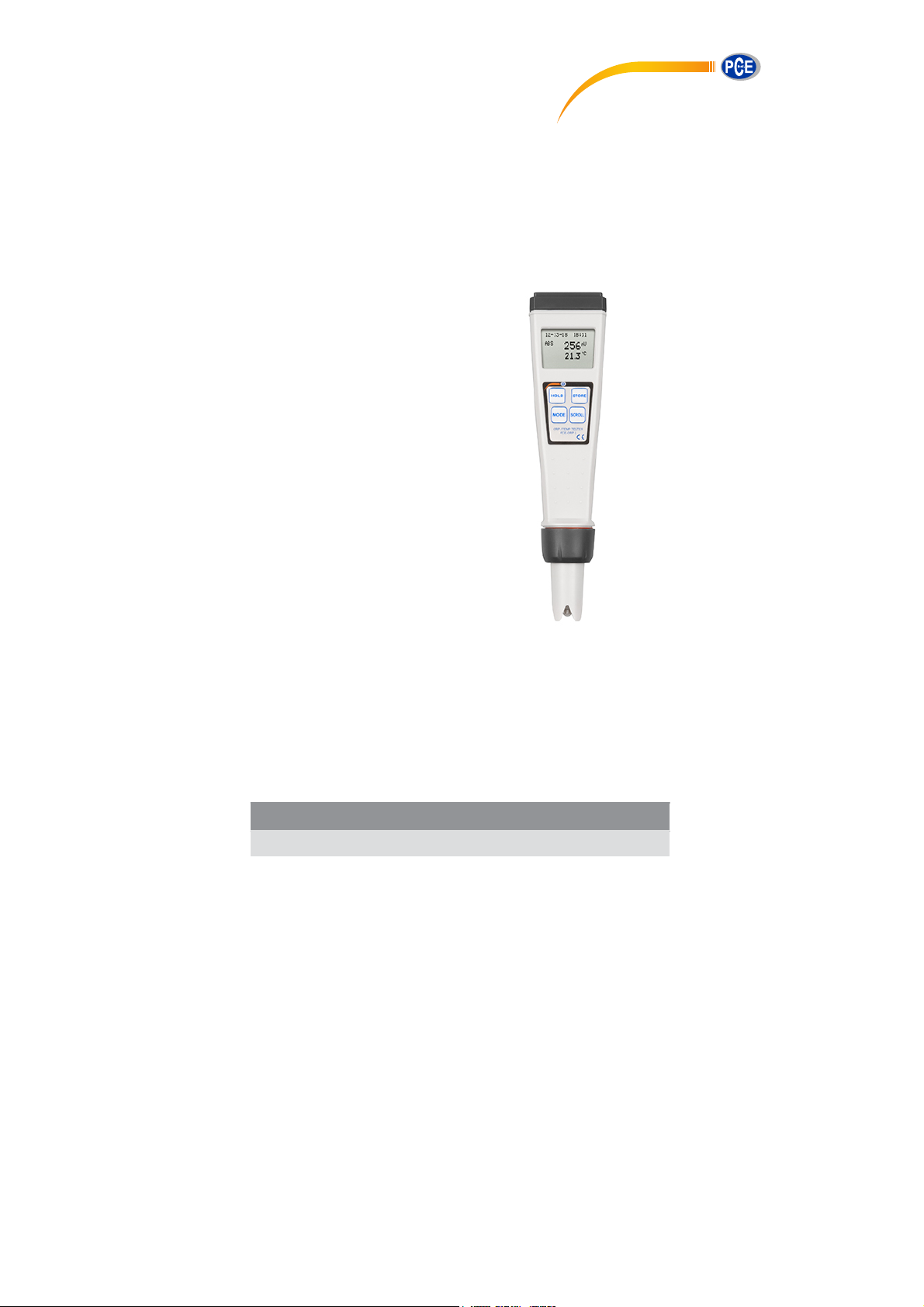
Operation Manual
PCE-ORP 3
Microcomputer Based
ORP & Temperature
Pocket Meter
PCE-ORP 3
Page 2

CONTENTS
INITIAL INSPECTION AND ASSEMBLY .....................2
BEFORE YOUR FIRST USE........................….............2
A. Replace the Batteries ............................................2
B. Soak the Electrode
C. Setup and Calibrate the Electrode and Meter
PCE-ORP 3 OVERVIEW...............................................3
A. Meter Description..................................................3
B.
PCE-ORP 3 Graphical Display ...............................3
OPERATION MODES AND KEYPAD OPERATIONS..4
A. Operation Modes...................................................4
B. Keypad Operations ................................................4
USING PCE-ORP 3........................................................5
A. Power ON/OFF ......................................................5
B. Set Date and Time
C. Relative ORP calibration
D. Measure
E. Hold Data
F. Save Data
G. Recall Data
H. Erase Data .............................................................7
…….........................................................6
.......... ....................................................6
.... ...........................................2
...........2
..................................................5
.........................................6
............................................................6
..........................................................7
ONGOING MAINTENANCE...........................................7
A. Replace Electrode..................................................7
ERROR DISPLAYS AND TROUBLESHOOTING ……..8
SPECIFICATIONS .........................................................8
1
Page 3
INITIAL INSPECTION AND ASSEMBLY
Carefully unpack the instrument and accessories. Inspect for
damages made in shipment. If any damage is found, notify your
Jenco representative immediately. All packing materials should be
saved until satisfactory operation is confirmed.
BEFORE YOUR FIRST USE
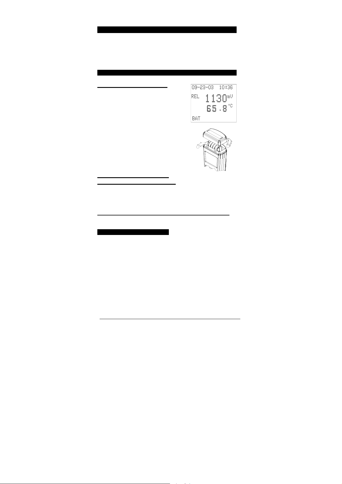
A.
Replace the Batteries
Rep
lace the battery when the blinking
low battery indicator “BAT ” appears on
the lower left hand side of the LCD
screen. The instrument can operate
within specifications for
approximately2~3 hours after low
battery indicator appears.
1. Show
2. T
3. Remove a
n in the
ake off the battery
insert a new set of batteries ensuring
the polarit
right figure.
cover.
ll of the old batteries
ies are correct.
and
1
2
B. Soak the Electrode, if
necessary for up to 24 hours
1. Remove the electrode cap covering the VisionPlus ORP meter.
2. Soak the ORP electrode in standard solution
wa
ter for 10 minutes
before first use or after storage.
or distilled
C. Setup and Calibrate the Electrode and Meter
PCE-ORP 3 must be setup and calibrated before your first use.
Please follow the instructions detailed in section USING VPCE-
USING PCE-ORP 3
2
Page 4

PCE-ORP 3 OVERVIEW
A. Meter Description
1. Battery cap
1
2. LCD screen
2
3. Keypad
4. Electrode collar
3
5. Electrode & ATC assembly
(Electrode cap is not shown.)
4
5
B. PCE-ORP 3 Graphical Display
1
2
3
TE (MM-DD-YY)
1. DA
2. ABSolute or RELative ORP mode indicator
3. HOLD mode indicator
4. TIME (HH:MM – 24H format)
5.
ORP
reading & unit
EMPERATURE reading & unit
6. T
Note: ℃
or °F is factory pre-set.
3
4
5
6
Page 5
OPERATION MODES AND KEYPAD OPERATIONS
A. Operation Modes
. PCE-ORP 3 meter has 7 operation modes:
1. Measure Mode.--Measure Mode is used to make all absolute or
relative ORP and temperature measurements.
2. Calibration Mode.--Calibration Mode is used to perform offset
voltage adjust.
3. Hold Mode.--Hold Mode is used to display held measured values
for increased ease of use.
4. Recall Data Mode.--Recall Data mode is used to display
measured data which have been stored in memory.
5. Store mode.--Can save up to 50 set data in non- volatile memory.
6. Date and Time Set Mode.--Date and Time Set Mode is used to
change date and time.
7. Erase Mode.--Can erase 50 set data in non- volatile memory.
B. Keypad Operations
Key
HOLD
MODE
STORE
Operation
Mode
All, except Hold
Measure 0 second
Hold 0 second Returns to Measure Mode.
Date and Time
Set
Calibration 0 second
Measure 2 seconds Enters Calibration Mode.
Measure
Calibration 0 seconds Increases current number.
Date and Time
Set
Measure 2 seconds
Calibration
Duration Function
2 seconds or
more
0 second
10 seconds or
more
0 seconds Increases current number.
2 seconds or
more
Turns meter on/off.
Holds current measurement
reading. Press again to
resume measuring.
Moves cursor to next set of
data.
Moves cursor to next digit
or sign.
Enters Date and Time Set
Mode.
Stores Temperature,
current absolute & relative
ORP reading, date and
time into memory.
Leaves Calibration Mode.
4
Page 6

Date and Time
RE
Date and Time
Operation
Mode
Recall Data
Set
Erase 0 second
Measure 2 seconds Enters Recall Data Mode.
Recall Data
Calibration
Set
Measure
Erase
Duration Function
2 seconds or
more
2 seconds or
more
0 second
0 second
0 second
10 seconds
or more
0 second Exits Erase Mode
Leaves Recall Data Mode.
Leaves Date and Time
Set Mode.
Erases all user data then
Exits Erase Mode.
Scrolls through stored data.
Decreases current number.
Decreases current number.
Enters Erase 50 set non-
volatile memory mode.
Key
STO
SCROLL
USING PCE-ORP 3
A. Power ON/OFF & Shutdown
Press “HOLD” key for 2 seconds or more. The unit will turn on and
enter the “Measure Mode”. Repeat the process to turn off the unit.
The unit will also automatically turn off after 10 minutes of no key
activity.
B. Set Date and Time
1. Press “MODE” key for 10seconds or more to enter“Date and Time
Set Mode”.
2. Press “HOLD” key to
selectca
lendar or
parameters.
Press “MODE” and “SCROLL”
3.
key
s to increase and decreas
val
ues respectively
Press “STORE” key for 2
4.
seconds to ex
time
e
.
it and return to“Measure Mode”.
5
Page 7
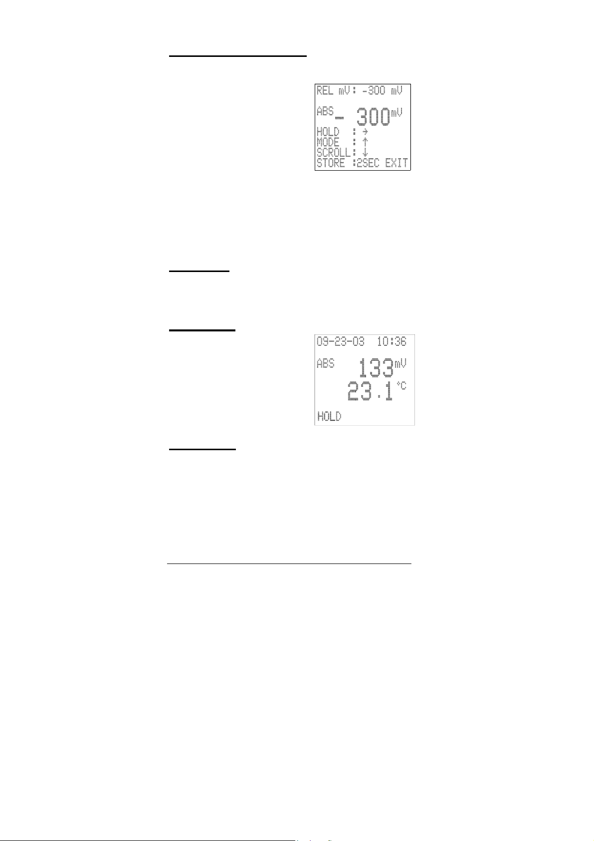
C. Relative ORP Calibration
If the user requires a relative ORP calibration, follow these steps:
1. Clean and dip meter into
standard solution .
2.Wait reading stable, press
“MODE” key
to enter “Calibration” mode and
enter new relative ORP value.
ess “HOLD” key to move the
Pr
3.
digit position ( polarity & digit).
4.
Press “MODE” and “SCROLL”
keys
values respectively.
Press “STO
5.
mode dis
Press “MODE” key
6.
Note:
1. The ORP offset calibration is only needed in some applications.
2. Don ’t enter calibration mode when absolute reading is over ±1000
mV range.
for
2 to 3 seconds
to increase and decrease
RE” key for 2 seconds to exit and return to measure
playing absolute ORP
to displa
value.
y relative ORP value.
D. Measure
The ORP/TEMP can be used to measure absolute or relative ORP
values.
1. Dip the meter into the test solution in the “Measure Mode”.
2. Press “MODE” key to select absolute or relative ORP readings.
E. Hold Data
1. When the ORP reading is
stable, press “HOLD” key once
to lock the reading.
Note: The unit cannot be power
off in “Hold Mode”.
2. Press “HOLD” key again to
unlock reading and the unit will
return to “Measure Mode”. The
unit is now ready for another
measurement.
F. Save Data
1. Either in the “Hold Mode” or the “Measure Mode”, press “STORE”
key for 2-3 seconds. The “ SAVE” and “M-XX” icons will appear
indicating the reading has been saved and stored in memory
location XX. The unit will automatically returns to “Measure Mode”
and ready to perform other task.
Note: The PCE-ORP 3 is equipped with a non-volatile
memory that can store up to 50 different sets of readings
6
Page 8
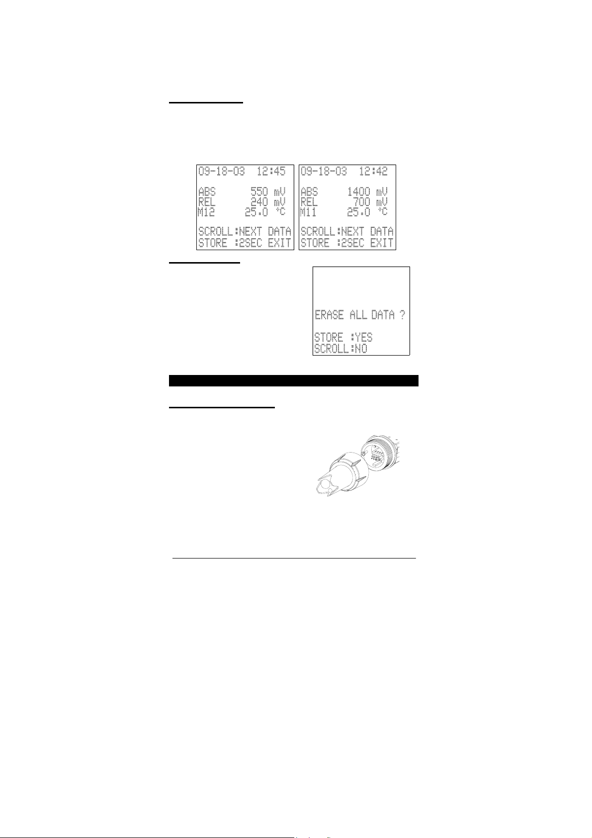
(ABSolute & RELative mV, temperature, Time and date).Nonvolatile memory will be retained even if power is lost. When all
memory locations are used up, the next set of data saved
50
will overwrite the data stored in the first location and so on.
G.
Recall Data
1. In “Measure Mode”, press “SCROLL” key 2-3 seconds, the last
set (assume it is
2. B
y pressing the “SCROLL” key, previous ( M11) saved data w
appear.
3. Press “ST
Mode.
M12) of saved data will appear
ORE” key for 2 seconds to exit and return to “Meas
.
H. Erase Data
1. Press “SCROLL” key over 10
seconds to enter erase mode.
See the figure b
2.
Press “STORE” key,
ill display “DATA CLEAR” and
w
erase all data in the nonvolatile memory.
3.
Press “SCROLL” key
the erase mode and return to
“Measure Mode”.
elow.
the unit
to leave
ill
ure
ONGOING MAINTENANCE
Replace Electrode
A.
It is recommended the ORP electrode be replaced every 6 to 12
months or as needed. Some applications can severely limit
the life span of an ORP electrode.
1. Unscrew
remove the elec
assemb
figure
2. Remove the old electrode from the
electrode collar
3. Insert a ne
meter correctl
4. Screw
the electrode co
ly as show
trode & AT
n in the right
.
.
w electrode, make su
y.
back the electrode collar
llar to
C
re the electrode fit back into the
.
7
Page 9
ERROR DISPLAYS AND TROUBLESHOOTING
ORP
LCD
Display
Any
Value
"OVER"
or
"UNDER"
ATC
Display
"OVER"
or
“UNDER”
-10.0~
100.0°C
DISPLAY
Mode
Measure
Measure
Possible cause(s)
[Action(s)]
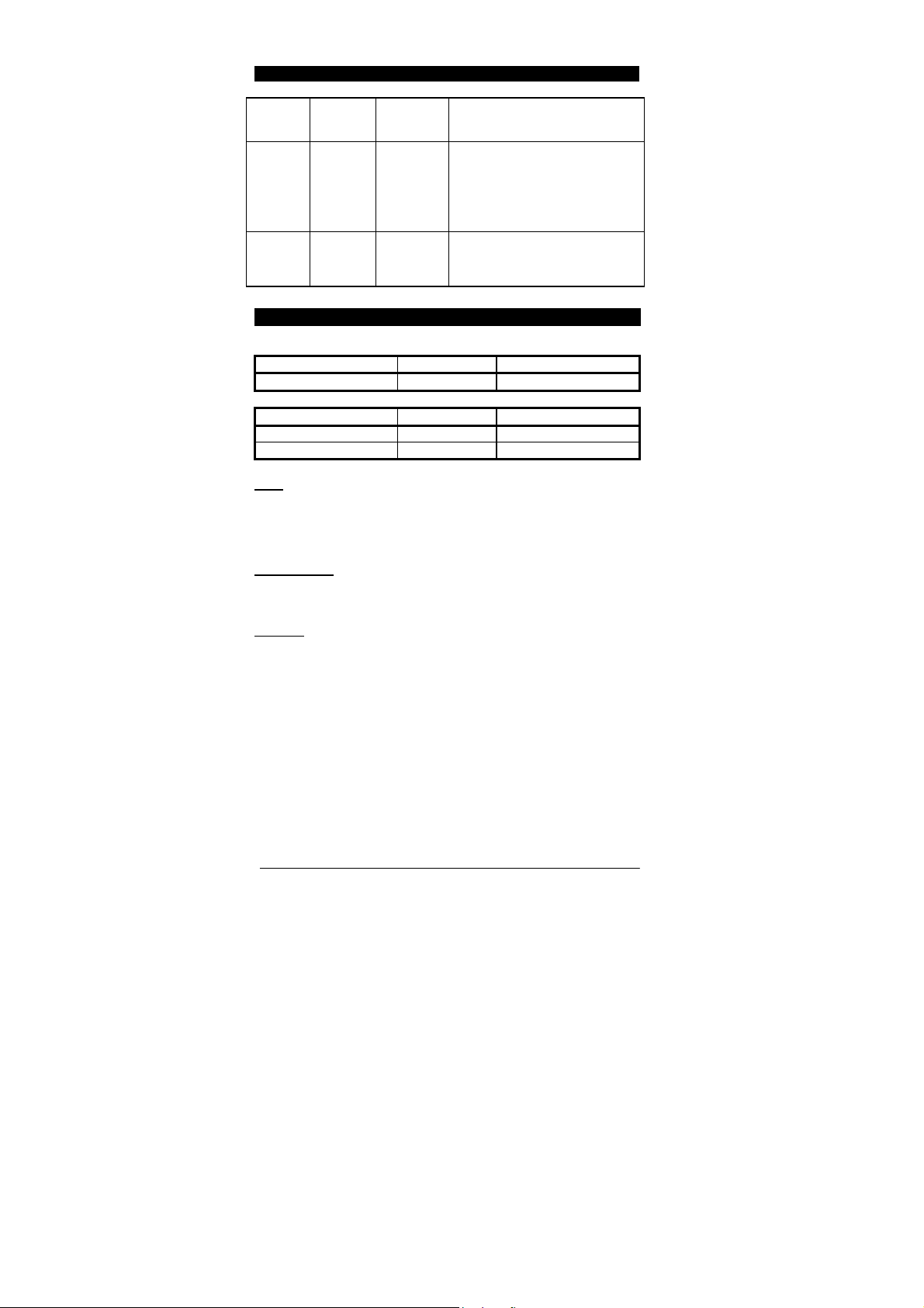
a. Temperature outside –10.0 to +
100.0°C range.
[Bring solution to a lower/higher
temperature.]
b. Bad sensor.
[Replace new electrode module .]
ORP value outside -1100 to +1100
mV value.
[Clean or Replace electrode]
SPECIFICATIONS
ORP
Absolute Range Resolution Accuracy
-1100 to +1100mV 1 mV 1 mV ± 1 LSD
Temperature
e Reso
Rang
-10.0 to 100.0 °C 0.1 °C ±0.3 °C
14.0 to 212.0 ℉ 0.2 ℉ ±0.6℉
OR
P
Relative ORP calibration
Input impedance >10
lution Accuracy
range –
999
to 999 mV
(User programmable)
12
T
emperature
Temperature sensor Thermistor, 10K@ 25°C
Temperature unit Default in factory (°C or )℉
General
Power Meter : LR44 x 4
Calendar : CR2032
Battery life Meter: 200 Hours
Calendar: 5 years
Ambient temperature range 0.0 to 50.0 °C
Display 98x64 graphic LCD
Case IP67 water-tight Case
Weight 107 g
8
 Loading...