

Page 1
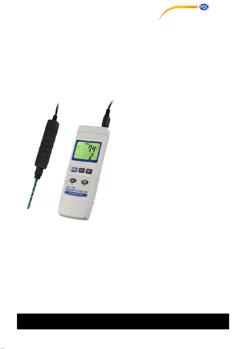
PCE-MFM 3000
R
g
g
g
PCE Americas Inc.
711 Commerce Way
Suite 8
Jupiter
FL-33458
USA
From outside US: +1
Tel: (561) 320-9162
Fax: (561) 320-9176
[email protected]
www.pce-instruments.com/english
www.pce-instruments.com
PCE Instruments UK Ltd.
Southpoint Business Park
Ensign way
Hampshire / Southampton
United Kingdom, SO31 4RF
From outside UK: +44
Tel: (0) 2380 98703 0
Fax: (0) 2380 98703 9
G ( Gauss), mT ( milli Tesla ), USB/RS232
MAGNETIC FIELD METER
Your purchase of this
AC/DC MAGNETIC METE
marks a step forward for
you into the field of
precision measurement.
Althou
complex and delicate
instrument, its durable
structure will allow many
years of use if proper
operatin
developed. Please read the
followin
carefully and always keep
this manual within easy
reach.
h this METER is a
techniques are
instructions
Unit 11
OPERATION MANUAL
Page 2

TABLE OF CONTENTS
.
.
g
g
.
.
.
.
.
g
.
g
g
.
.
1. FEATURES..................................................................1
2. SPECIFICATIONS........................................................
3. FRONT PANEL DESCRIPTION......................................
3-1 Display.................................................................4
3-2 Power Button........................................................4
3-3 Hold Button.......................................................... 4
3-4 REC Button...........................................................4
3-5 ZERO Button ........................................................4
3-6 Mode Button ( DC, AC Button ), SET Button............4
3-7 Input socket.........................................................
3-8 Probe Handle........................................................4
3-9 Probe Sensin
3-10 Probe Plu
3-11 Probe Head Cover...............................................
3-12 RS-232 Output Terminal...................................... 4
3-13 Reset button.......................................................4
3-14 DC 9V Power Adapter Input Socket......................
3-15 Stand.................................................................
3-16 Tripod Fix Nut.....................................................4
3-17 Battery Compartment/Cover................................
3-18 Battery Cover Screw............................................4
4. MEASURING PROCEDURE...........................................
4-1 AC/DC ma
4-2 Data Hold.............................................................7
4-3 Data Record.........................................................
5. ADVANCED SETTING.................................................. 8
5-1 Auto power OFF mana
5-2 Chan
5-3 For the further calibration usage, not available
for the user..........................................................10
6. RS232 PC SERIAL INTERFACE.....................................10
7. BATTERY REPLACEMENT............................................
8. SYSTEM RESET..........................................................
e the unit ( mT, G )......................................9
Head.............................................. 4
..........................................................4
netic field measurement........................5
ement................................9
2
4
4
4
4
4
4
5
7
11
12
Page 3

1. FEATURES
* Wide range, general purpose magnetic measurement for
industrial, mechanical, material, electrical, laboratory
field usage
* Unit : G ( Gauss ), mT ( milli Tesla )
* DC and AC magnetic field measurement
* DC Range : 300.00 mT/3000.0 mT
AC Range : 150.00 mT/1500.0 mT
* Resolution : 0.01/0.1 mT, 0.1/1 G
* N pole/S pole indicator
* Use Hall sensor with automatic Temp. compensation
* Zero button for DC, AC magnetic function
* Separate probe, easy operation and convenient
for remote measurement
* Data hold function for freezing the desired value
on display
* Records Maximum and Minimum readings with Recall
* RS232/USB computer interface
* Microprocessor circuit assures maximum possible
accuracy, provides special functions and features
* Heavy duty & compact housing with hard carrying case,
designed for easy carry out & operation
* Auto shut off is available to save battery life
* Power supply from batteries or DC 9V adapter in
1
Page 4
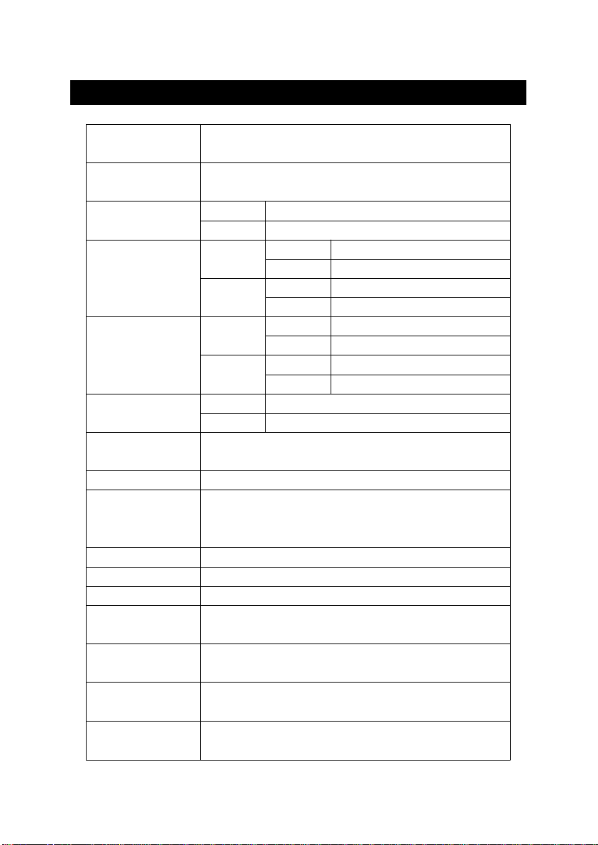
2. SPECIFICATIONS
Circuit Custom one-chip of microprocessor LSI
circuit.
Display LCD size : 52 mm x 38 mm
dual function LCD display.
Measurement mT milli Tesla
Unit G Gauss
Measurement mT Range 1 300.00 mT x 0.01 mT
Range, DC Range 2 3,000.0 mT x 0.1 mT
G Range 1 3,000.0 G x 0.1 G
Range 2 30,000 G x 1 G
Measurement mT Range 1 150.00 mT x 0.01 mT
Range, AC Range 2 1,500.0 mT x 0.1 mT
G Range 1 1,500.0 G x 0.1 G
Range 2 15,000 G x 1 G
Accuracy DC ± ( 5 % rdg. + 10 digit )
(at 23± 5 )℃ AC ± ( 5 % rdg. + 20 digit )
Frequency AC measurement :
Response 50 Hz / 60 Hz
Sensor Hall sensor.
Temp. Probe head build the Temp. sensor
Compensation for using the ATC ( automatic Temp.
for hall sensor compensation ).
Field Direction Uniaxial.
Data Hold Freeze the display reading.
Memory Recall Maximum & Minimum value.
Display Approx. 1 second.
Sampling Time
Power off Manual off by push button or
Auto shut off to save battery life.
Operating 0 to 50 .℃
Temperature
Operating Less than 85% R.H.
Humidity
2
Page 5
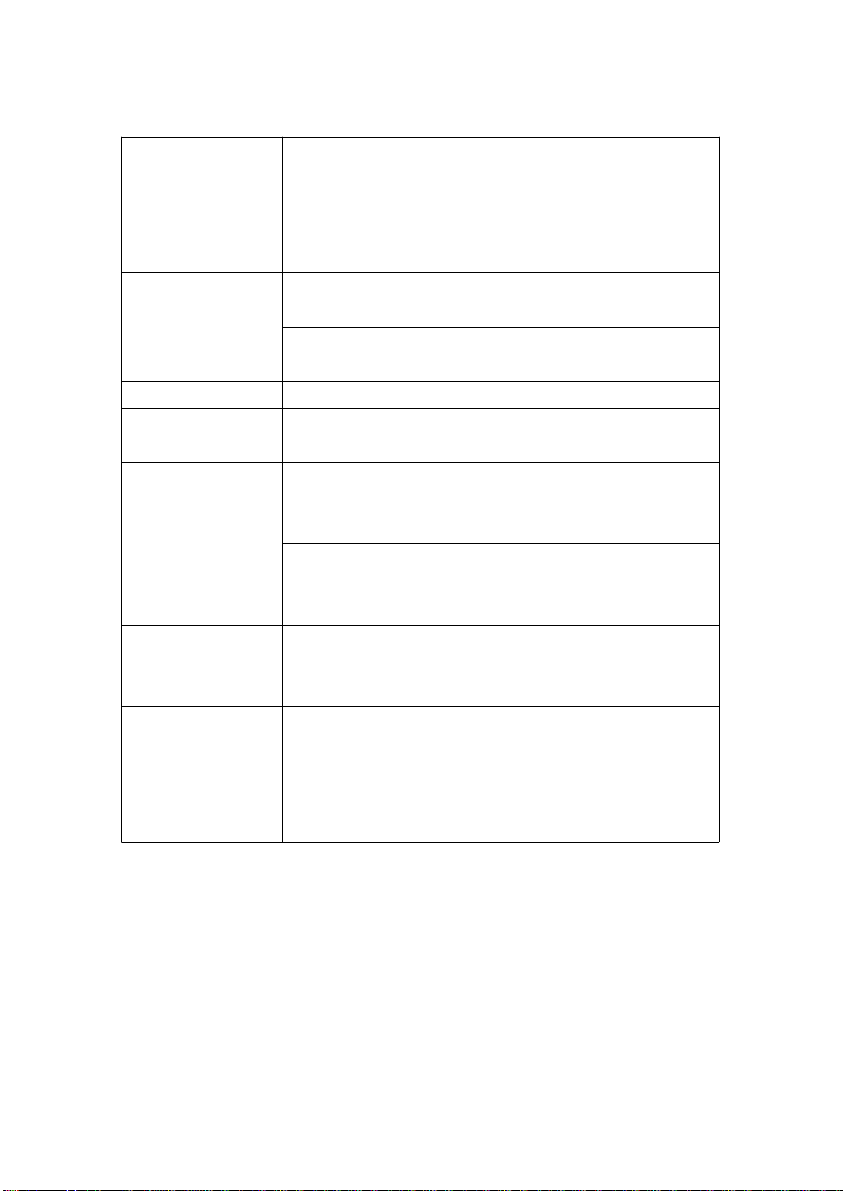
Data Output RS 232/USB PC serial interface.
*
*
g
Connect the optional RS232 cable
UPCB-02 will get the RS232 plug.
Connect the optional USB cable
USB-01 will get the USB plug.
Power Supply 006P DC 9V battery
( Alkaline or Heavy duty type ).
DC 9V adapter input.
* AC/DC power adapter is optional.
Power Current Approx. DC 15 mA .
Weight Approx. 275 g/0.61 LB.
( include probe )
Dimension Main instrument :
198 x 68 x 30 mm
( 7.8 x 2.7 x 1.2 inch )
Probe :
195 x 25 x 19 mm
( 7.7 x 1.0 x 0.7 inch ).
Accessories Instruction manual.......................1 PC
Included Ma
netic Probe............................1 PC
Carrying case............................... 1 PC
* Above specification tests under the environment RF Field Strength less than 3
V/M & frequency less than 30 MHz only.
3
Page 6
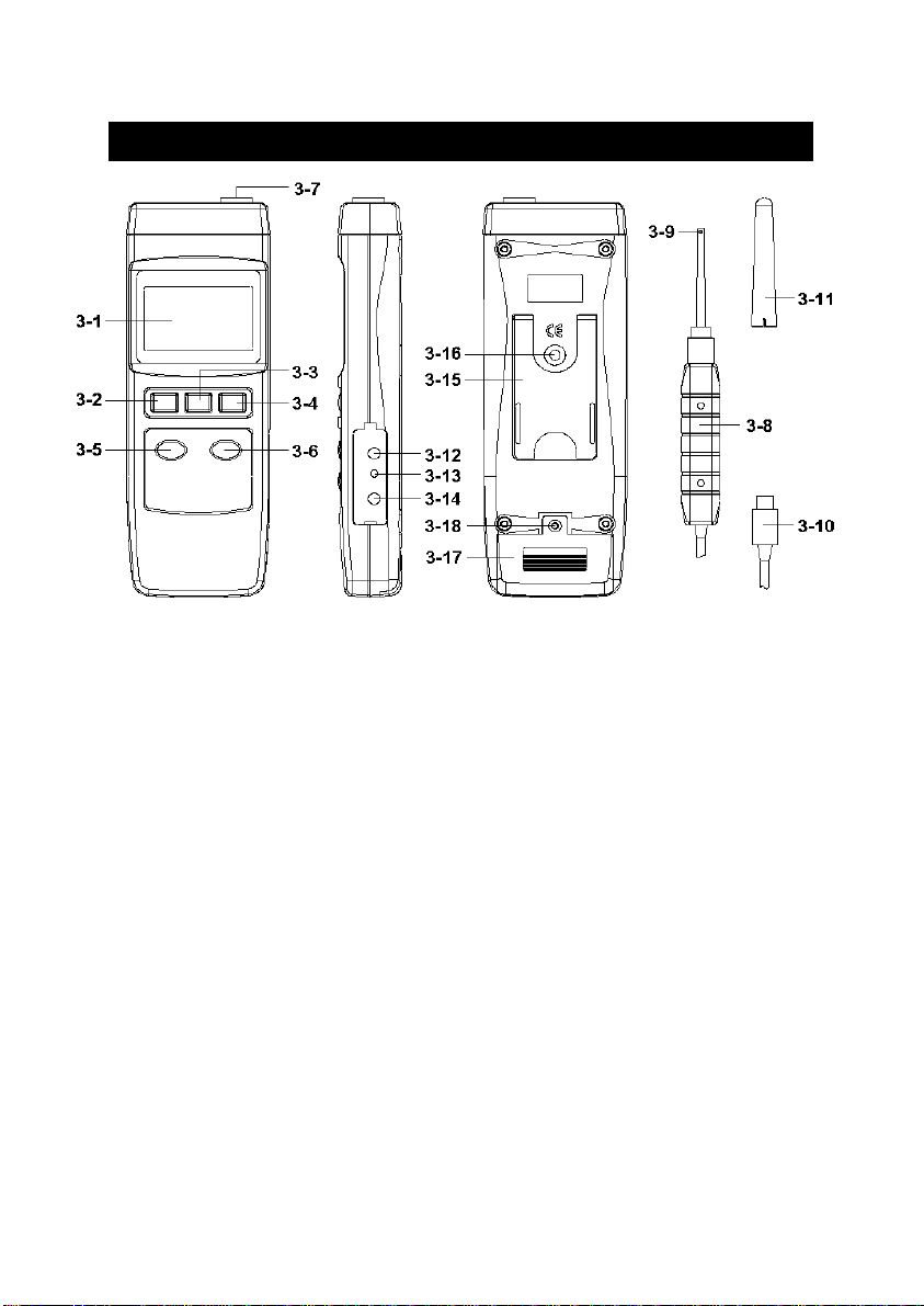
3. FRONT PANEL DESCRIPTION
Fig. 1
3-1 Display
3-2 Power Button
3-3 Hold Button
3-4 REC Button ( Enter Button )
3-5 ZERO Button
3-6 Mode Button ( DC, AC Button ), SET Button
3-7 Input socket
3-8 Probe Handle
3-9 Probe Sensing Head
3-10 Probe Plug
3-11 Probe Head Cover
3-12 RS-232 Output Terminal
3-13 Reset button
3-14 DC 9V Power Adapter Input Socket
3-15 Stand
3-16 Tripod Fix Nut
3-17 Battery Compartment/Cover
3-18 Battery Cover Screw
4
Page 7
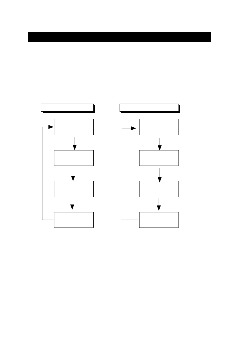
Fig. 2
4. MEASURING PROCEDURE
4-1 AC/DC magnetic field measurement
1)Power ON the meter by pressing the " Power
Button " ( 3-2, Fig. 1 ) once.
2)Press the " Mode Button " ( 3-6, Fig. 1 ) once ,
the Display will show the following screen in sequence :
Under mT unit Under G unit
N(S) 0 mT a1 N(S) 0 G a2
.0 0
N(S) 0.0 mT b1 N(S) 0 G b2
0 .0
0 mT c1 0 G c2
.0
AC 0 AC
0.0 mT d1 0 G d2
0
AC .0 AC
Note :
a1 screen is ready for DC 0.1 mT resolution measurement.
b1 screen is ready for DC 0.01 mT resolution measurement.
c1 screen is ready for AC 0.1 mT resolution measurement.
d1 screen is ready for AC 0.01 mT resolution measurement.
a2 screen is ready for DC 1 G resolution measurement.
b2 screen is ready for DC 0.1 G resolution measurement.
c2 screen is ready for AC 1 G resolution measurement.
d2 screen is ready for AC 0.1 G resolution measurement.
5
Page 8

3) Display indicator
DC magnetic field measurement
* The Display will show " N " or " S " indicator
* North pole : Display will show " N " indicator
* South pole : Display will show " S " indicator
AC magnetic field measurement
* Display will show " AC " indicator.
* Display will not show " N (S ) indicator.
4)unit selection :
How to select the unit ( mT, G ), the procedures please
refer to chapter 5-2 " Change the unit ( mT, G ) ", page 9.
5)Contact and close the testing material to the probe
head ( refer to Fig. 3 ) , the Display will show the magnetic
field value along with the unit ( mT, G ).
Contact side ( measuring face )
6
Fig. 3
Page 9

6)Zero adjustment :
When power ON the meter, due to the environment
interference, the display may show certain values ( not
zero value), it is normal.
* Before the measurement, fix the probe at the exact
position, press the " ZERO Button " ( 3-5, Fig. 1 ),
in the same time the display will show the " 0 "
indicator.
4-2 Data Hold
During the measurement, press the " Hold Button " ( 3-3,
Fig. 1 ) once will hold the measured value & the LCD will
display a " HOLD " symbol.
* Press the " Hold Button " once again will release the data
hold function.
4-3 Data Record ( Max., Min. reading )
* The data record function records the maximum and
minimum readings. Press the " REC Button " ( 3-4, Fig.
1 ) once to start the Data Record function and there
will be a " REC " symbol on the display.
* With the " REC " symbol on the display :
a)Press the " REC Button " ( 3-4, Fig. 1 ) once, the "
REC MAX " symbol along with the maximum value
will appear on the display.
If intend to delete the maximum value, just press
the " Hold Button " ( 3-3, Fig. 1 ) once, then the
display will show the " REC " symbol only & execute
the memory function continuously.
7
Page 10

b)Press the " REC Button " ( 3-4, Fig. 1 ) again, the
.
" REC. MIN " symbol along with the minimum value
will appear on the display.
If intend to delete the minimum value, just press
the " Hold Button " ( 3-3, Fig. 1 ) once, then
the display will show the " REC " symbol only &
execute the memory function continuously.
c)
To exit the memory record function, just press the
" REC Button " for 2 seconds at least. The display will
revert to the current reading.
Remark :
When make the DC magnetic field measurement
and execute the " RECORD " function, it can not
change from the " North pole " to " South pole "
or from the " South pole " to " North pole "
during the measurement. It can make the
measurement under the same pole ( S pole or N
pole ) only, otherwise the Max., Min. value will
be no sense.
5. ADVANCED SETTING
Press the " SET Button " ( 3-6, Fig. 1 ) continuously at
least two seconds will enter the " Advanced Setting " mode,
then press the " SET Button " ( 3-6, Fig. 1 ) once a while
in sequence to select the three function, the lower Display
will show :
PoFF.....Auto power OFF management
unit......
CLr....... For the further calibration usage, not available
Select the measurement unit to mT or G
for the end user
8
Page 11

5-1 Auto power OFF management
When the lower display show " PoFF "
1)Use the " REC Button " ( 3-4, Fig. 1 ) to enter
will enter into the setting of " Auto power off
management ".
Press the " Mode Button " ( 3-6, Fig. 1 ) once in sequence
to select upper text to " yES " or " no ".
yES - Auto Power Off management will enable.
no - Auto Power Off management will disable.
2)
After select the desiring function ( YES or no ), press the
" REC Button " ( 3-4, Fig. 1 ) to save the function with
default.
5-2 Select the measurement unit to mT or G
When the lower display show " unit "
1)Use the " REC Button " ( 3-4, Fig. 1 ) to enter
will enter into the setting of " Select the measurement
unit of mT or G "
Press the " Mode Button " ( 3-6, Fig. 1 ) once in sequence
to select the Display text to " t " or " g ".
t - milli Tesla ( mT )
g - Gauss ( G )
2)
After Display unit is selected to " mT " or " G ", press the
" REC Button " ( 3-4, Fig. 1 ) will save the setting
function with default.
9
Page 12
5-3 For the further calibration usage, not available
.
for the user
When the lower display show " CLr "
This setting just for the further calibration usage, not
available for the end user.
6. RS232 PC SERIAL INTERFACE
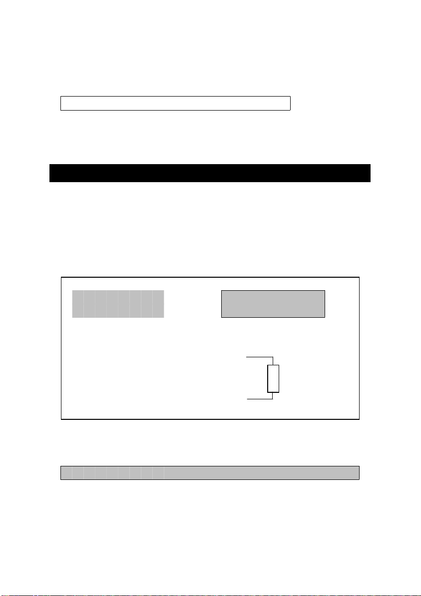
The instrument has RS232 PC serial interface via a 3.5
mm terminal ( 3-12, Fig. 1 ). The data output is a 16
digit stream which can be utilized for user's specific
application. A RS232 lead with the following connection
will be required to link the instrument with the PC serial port.
Meter PC
(3.5 mm jack plug) (9W 'D" Connector)
Center Pin..........................Pin 4
Ground/shield......................
The 16 digits data stream will be displayed in the
following format :
D15 D14 D13 D12 D11 D10 D9 D8 D7 D6 D5 D4 D3 D2 D1 D0
Pin 2
2.2 K
resister
Pin 5
10
Page 13
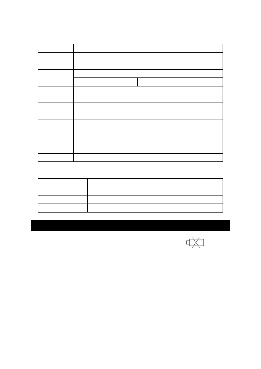
Each digit indicates the following status :
1)When the left corner of LCD display show " ", it
D15 Start Word = 02
D14 4
D13 1
D12 & Annunciator for Display
D11 m tesla = E3 gauss = B5
D10 Polarity
0 = Positive 1 = Negative
D9 Decimal Point(DP), position from right to the
left, 0 = No DP, 1= 1 DP, 2 = 2 DP, 3 = 3 DP
D8 to D1 Display reading, D8 = MSD, D1 = LSD
For example :
If the display reading is 1234, then D8 to
D1 is : 00001234
D0 End Word = 0D
RS232 setting
Baud rate 9600
Parity No parity
Data bit no. 8 Data bits
Stop bit 1 Stop bit
7. BATTERY REPLACEMENT
is necessary to replace the battery. However, in-spec.
measurement may still be made for several hours after
low battery indicator appears before the instrument
become inaccurate.
Loose the " Battery Cover Screw " ( 3-18, Fig. 1 ), slide
2)
the " Battery Cover " ( 3-17, Fig. 1 ) away from the
instrument and remove the battery. Replace with DC 9
V battery ( 006P Alkaline/heavy duty ), and reinstate
the cover.
3)Make sure the battery cover is secured after changing
the battery.
11
Page 14

8. SYSTEM RESET
If the meter happen the troubles such as :
CPU system is hold ( for example, the key button can
not be operated... ).
Then make the system RESET will fix the problem.
The system RESET procedures will be either following
method :
During the power on, use a pin to press the " Reset
Button " ( 3-13, Fig. 1 ) once a while will rest the
circuit system.
12
 Loading...